Intro
For this article I will be using various vacuum rectifier tubes, for the purpose of checking the X-Ray emission in cases of over-voltage. I will try to indicate the field distribution, emission angles, and other measurable details.
Each of my experiments will be indexed like 01, 02, etc. I will also indicate the tube used, the voltage level, whether it was connected in normal polarization (meaning the Supply HV+ goes to tubes Anode) or inverse polarization (HV+ goes to the tube’s bottom pins, connected together, and HV- goes to the Tube’s anode). Also photography details such as fluorescent screen type, camera, exposure times, will be indicated.
A few assumptions were wrong at first, but the thread eventually got to describing the true course of events related to the phenomenon.
Safety: There will be an entire post dedicated to safety below, however I should point out that all my tests are performed remotely, and the camera is set on a tripod, with a timer. I also use a few dosimeters to at least indicate the presence of x-rays, since they are not well suited for dosing the emission precisely: Radex 1706 (30keV minimum sensitivity), Terra-P, Kvarts DRSB01, CDV 700.
Power supply: I’m currently using my DIY 50KV Variable supply: (ZVS + Multiplier in paraffin). For all the tests below, unless otherwise indicated, the complete system is powered from a regulated variable DC supply, currently set at 12V (20amps max).
See the following posts for the latest results.
Here is just a quick introductory set of the successful results:


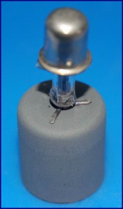
Photo 1: 2X2 tube, inverse polarization (HV+ to Tube pins, HV- to Anode) 50KV, 15 s exposure, f/3.5, ISO 100. Photo 2: same, different setup Photo 3: determining the x-ray distribution field test


Photo 1&2: The same remote control while being illuminated by the 2X2 . Photo 3: SD Card
01. Jan 16, 2011: First Tests
Note: This first test uses a 2X2 connected in normal polarization.
Objective 1: demonstrate x-ray emission.
Objective 2: Verify the x-ray level is suitable for photography
The characteristics of the 2×2 Russian rectifier have been discussed here.
I recently acquired a few of these tubes, so I run a few tests of over-volting them using my 50KV supply:

The system was triggered remotely, from safe distance (more then 6 meters) with concrete walls in between. The camera used to capture the results is a Canon S2 IS, operated using the timer function. The camera was set on a tripod, at 1.5meters away from the 2X2, and the zoom set to maximum. Focus was set to manual.
For these first tests, a limiting resistor was added in series with the supply. The tube’s anode was connected to positive.
A Radex 1706 dosimeter, set in close proximity of the tube (15cm), indicated more the 800uSv/h in just 3 seconds of operation. At aprox. 80cm, the value dropped to 200uSv/h (Background level 0.13uSv/h). At two meters, the Radex was still detecting a high level. The datasheet of this dosimeter indicates it is capable of detecting X-rays of minimum 30keV.
The purpose of these tests was to determine if a radiography is at least possible using this setup. Fluorescent screens of 4 different types where used:
1. A first test, to see if the fluorescent screen emits any light:

8 seconds exposure, f/3.5, ISO 200
2. An object (a remote control) was added between the 2X2 and the fluorescent screen. For all the pictures here, the fluorescent screen was placed immediately after the remote control, and the distance from the tube was 5-8cm.


Exposure: 10s , f/3.5, ISO 400 , Green emitting fluorescent screen 1 (will add type later)
3. Using a blue emitting fluorescent screen:


Exposure: 10s , f/3.5, ISO 400
02. Jan 17, 2011: Experiment inverse polarization
Note: Tube used 2X2. The tube was position at a very small angle from the screen plan normal, at a distance of 4cm.
Objective: compare the normal polarization emission with inverse polarization
The first image was taken with the 2X2 tube powered by connecting HV+ to Anode. The second picture has the connections reversed, the 2X2 has the anode connected to HV- , and the bottom pins connected together to HV+. The difference is obvious.


So using this reversed connection, here are some results:


The quality is good enough to actually use this radiograph for seeing the internals. A very cheap solution for a reasonably good image.
The 2X2 gets hot very quickly, the 15seconds needed for camera exposure are the maximum I would go for. Putting it under oil would probably solve this issue.
03. Jan 17, 2011: 6LJ6A (lead glass) Vacuum shunt tube
Objective: Use a 6LJ6A shunt with Lead Glass in inverse polarization setup with the 50KV source and check the x-ray emission as recorded by the camera . No dosimeter data available here.


Result: The intensifier screen shows no emission -or- emission too weak to be recorded using this technique.
The two objects are seen on the fluorescent screen, only as shadows, from the UV light generated inside the tube.
04. Jan 17, 2011: Some measurement attempts
Objective: Measure radiation output from the tube 2X2 in normal polarization at 50KV.
While waiting for a proper lead box to encapsulate this x-ray machine into a tiny self-contained device, here are some measurements. Unfortunately they seem to be quite unreliable. I might say that the best detector at this point, seems to be the fluorescent screen+camera combination. One of my new tests will be a box made of fluorescent screens, with tube placed inside, to provide a better idea on the field distribution and intensity.


These dosimeters are not suited for dosing the X-Rays, they might work for detecting them, but might not work at all. So they have to be considered unreliable, including the numbers in the pictures.
Picture 1: Radex 1706 and Terra-P Geiger Counters at 30 cm . The Radex seems to get saturated very quickly.
Picture 2: A CDV 700 Geiger counter set to x100 Scale.
Picture 3: A CDV 717 Ionisation chamber detector, set to x0.1 Scale, and placed at 15cm from 2X2.
Picture 4: The Radex 1706 at 50cm going for saturation
Picture 5: A 100uAmpmeter connected in series, goes past scale. Note the circuit is as follows:
(-)Bipolar HV Supply 50KV (+) —-> HV Limiting resistor —-> 2X2 Tube anode
|
|——> 100uAmpmeter——————————–> 2X2 Bottom pins together.
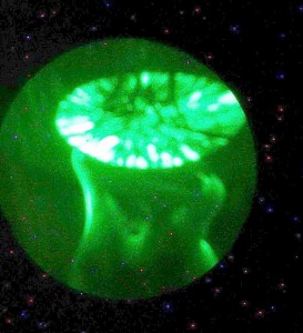
05. Jan 17, 2011: A Field distribution test
Note: A 2X2 Tube in inverse polarization at 50KV, placed with the anode towards the fluorescent screen (perpendicular on the screen’s surface):


Distance between the tube’s end and the screen: 3cm .
Comments: if the central black spot is probably a shadow caused by the metallic anode cap, then what is the bigger concentric shadow ring?
4HV Feedback Stella:If the 2X2 anode is made of molybdenum or nickel – which is quite probable – you will see one of the reasons why the X-ray output in the ‘normal’ tube polarity is so weak.
With a Mo anode, the bremsstrahlung is not plentiful, and the Kα emission only just on the edge of possible transmission through the glass.
And if the anode is nickel, the Kα emission won’t even get through the glass envelope:
Notice that there is no photon emission at all between about 40keV and 55keV for either metal – a very common phenomenon.
If we believe the worst of Cold War propaganda, and imagine that these Soviet 2X2s had an anode made from old scrap iron, we have
the same picture:
There is iron inside, I saw this when doing the neodymium magnets test, not sure if it’s the entire anode bell – but I don’t think so, since the attraction was weak – probably I was sensing just the steel wires holding the internals together.


06. Jan 19, 2011: A Field distribution test
Note: A 2X2 Tube in inverse polarization at 50KV. Setup looks like this:

Test1: The Z(vertical) axis:


Conclusion: As expected, on the vertical axis, the radiation is higher at the same level the anode is (the tungsten filament, under the bell). The bell doesn’t make any difference, in fact the radiation is higher where the bell is (it passes straight through).
Test 2: First 360° (X/Y) distribution results
The same setup was used and four images of the fluorescent screen where taken with tube at A=0° , A=90°, A=180°, A=270°. Distance from the tube was D=6 cm (another test with D=10cm was performed, but with the same results).
It was very important not to move the camera at all , not to change any distances, fluorescent screen position, etc, so the results would be comparable. Here are the 4 shots, with exposure/brightness improvement:


And after Segmentation Threshold was applied (Level=140):


Here’s is the tube, at 0°,90°,180°,270° in the same positions used to generate the images above:


Conclusions: The field distribution is uniform. The small changes in shape are only caused by the small metal plate, under the bell (easily visible by comparing the tube images with the blue fluorescent images). The source of radiation resulting from the 2X2 tube, should be visualized as a HOT, vertical rod, places inside the Bell. This rod, is , of course, the tungsten filament positioned vertically. The metallic bell produces almost no perturbation on the x-ray escaping it, however the small metal plate, under the bell is a strong blocker (it is not steel! what metal could that be?)
LE: the reason we get less radiation under the bell level is not entirely related to the small metallic plate, but also to the electric field distribution that causes the X-ray emissions: The electrons move from the bell to the inner tungsten filament, and produce x-rays, so we only get them between the bell and the internal filament. The metallic plate only blocks/attenuates a small ammount of rays that are oriented to the bottom of the tube. Most of them however are emitted perpendicular on the filament direction. X-RAY emission is therefore distributed like this:

The blue arrows are the electron paths, and the greens are the photons emitted. The internal filament represented in red is connected to HV+ and the external bell is connected to HV-.
Test 3: Another approach to 360° (X/Y) field distribution verification
A simpler test was performed, by surrounding the 2X2 with a tube made out of fluorescent material. Some extra attention was payed to keeping the 2X2 as close a possible to the center of the outer tube:


A very nice cylindrical,uniform emission field! The projected band appears to be quite narrow, related to the size of the vertical tungsten filament inside the tube. The picture to the right was added to observe the position of the tube elements as compared to the fluorescence projected on the intensifier screen.
This nice emission field can be used to project good quality radiographs, using this very cheap vacuum tube – the 2X2 .
The only concern is that the emission is radial (cylindrical shape with the center in the tungsten filament) but with some geometry knowledge unaltered, flat projections, can be obtained.
4HV Feedback Stella: X-ray production efficiency is roughly kV x Z x 10E-6, where Z is the Atomic Number – 74 in the case of W.
For an anode voltage less than 69.5 kV, there can be no K-characteristic radiation from a tungsten target, as the incident electron energy must exceed the K-shell binding energy for emission to occur.
This paper contains some very interesting observations on W target emission:
Soole BW The Attenuation of X-Radiation Generated at Constant Potentials Sufficient to Excite K-Radiation in a Tungsten Target Phys. Med. Biol., 1971, Vol. 16, No. 3, 427-437 . Link here. But let’s not jump to conclusions that the emission comes from W! Certainly the heater filaments will be either W, or a W/Mo alloy, but there are other metals besides in the construction of the valve.

07. Jan 19, 2011: Magnetic field influence
Note: A 2X2 Tube in inverse polarization at 50KV. A very strong Neodymium magnet was placed outside the tube, right next to the bell:

I took three pictures:
1) with the north pole of the magnet set towards the tube
2) without magnet
3) with the south pole of the magnet oriented towards the tube
The results:


Now the threshold (L=150):


In this setup, the magnet produces no visible influence on the emission field.
I am quite pleased of this method of highlighting the results by using image processing on the fluorescent screen shots. It shows a great potential of observing the x-ray phenomenon in more detail. Segmentation can be binary, as used up until now in my reports, but it can use several threshold levels and multiple colors to indicate various radiation levels. The following example shows two segmentation levels of 180 , corresponding to very intense radiation, and 140, corresponding to a decrease in radiation level:

An entire scale of intensities can be built this way with a corresponding color map legend.
4HV feedback Stella: I feel you should try the magnet experiment again, with the magnets lower down so the magnetic field bisects the open end of the anode bell and the electrode connection leads, where electron field emission is likely to be occurring.
There will be almost no electrons available for interaction with the magnetic field as you show it in the set-up in the picture. The anode bell will shield any electrons flying around inside from the magnetic field.
I also need to see the angle at which the narrow emission band expands with distance. This one:

To determine that I will use two fluorescent screen cylinders at a few cm apart.
Having a little software to do the segmentation automatically and create a map of colors would be useful. If I knew the Fluorescent screen fluorescence coefficient (must be something related to the energy of incident x-ray photon and the amount of visible light emitted), I could link it to the light intensity and compute the x-ray energy of the color map areas.The fluorescence surface would indicate the counts. That would a neat x-ray dosimeter. Eg:

Doing the same thing, but using several camera-captured frames, at a well known time interval, allows the time component to jump in the equation, so the Sv/h can be computed for a given color-map area.
08. Jan 21, 2011: A few x-rays images of various common objects
SDCard:


Mogo Bluetooth mouse ( it has a metallic side):


A piece of coral – blocks the rays completely!


The Kvarts DRSB-01 Dosimeter

As can be seen in the pictures, the optimal position of the tube is at 45 degrees, with the anode towards the fluorescent screen. This way a maximum uniform illumination surface is obtained (see the nice big square green glow with uniform intensity – less shadows). More on this in the next post. However some of the radiographs have issues with the shadows, especially when the subject is of a greater width / volume. Best results where obtained with thin objects such as the remote control exemplified above.
4HV Feedback Stella: The random star-like points of light are probably direct X-ray photon strikes on the CCD pixels.
The optimized tube angle suggests to me that the sharp edge of the anode bell is the source of field emission electrons which are impacting on the circular screening plate – though probably there are multiple sources of X-ray emission, some larger than others.
You can image the source directly with an X-ray pinhole camera, but I’d guess that your source is too weak to produce an image in this way
You may be able to improve resolution by means of a hole in a metal plate between the tube and the screen. You could try a hole of 10mm placed directly on the tube glass to start with.
Two or more holes spaced apart would make the simplest form of X-ray collimator.
09. Jan 21, 2011: Soft vs. Hard X-rays
Note: A 2X2 Tube in inverse polarization at 50KV. At 6cm a green fluorescent screen, with and without aluminum sheet shield.


Left picture: Fluorescent screen with Al sheet shield. Right picture: Threshold L=100


Left picture: Fluorescent screen without any shield. Right picture: Threshold L=100
Conclusion: the amount of soft x-rays seems to be negligible as compared to the hard x-rays. Possible causes: the tube’s glass envelope as a blocker -or- the fluorescence produced by the soft-xrays is overwhelmed by the stronger, more intense hard-xray fluorescence.
Feedback 4HV Stella: I think you should assume that the glass envelope blocks photons below about 15keV – with possible ranges across 12 – 18keV. So an aluminium filter will not have made much difference.
Expensive lead glass is not likely to have been used in 2X2, which was designed to rectify VRMS 5.5kV max.
The 2X2A iteration was a robust version of 2X2, “for applications critical as to severe shock and vibration” and may have had thicker, more radio-opaque glass, but I am just guessing.
How much the CCCP version followed the US design in glass technology, I have no idea.
10. Jan 21, 2011: Vertical emission angle
Note: A 2X2 Tube in inverse polarization at 50KV. A fluorescent screen at 6cm and then at 12cm. The tube is positioned vertically, tube’s longitudinal axis is parallel to the fluorescent screen plane (see pictures)


Note: The brightness has been increased in software, at 12cm the fluorescence is much fainter than at 6cm.


Laser level for bottom and top of 2X2’s bell
The measurements:


The vertical emission angle is 30°.


Some excellent news: using the laser level marker and three pictures taken to the same setup (two with laser visible, one with x-ray fluorescence) and software to combine the three images, it can be seen that the vertical’s angle bisector is perpendicular on the tube’s axis! The origin of the vertical emission angle is at the same height as the center of the bell ( as pictured)
So we got a very well centered / conveniently placed x-ray emission source. Too bad I won’t be using it in vertical position. The emission band is too narrow (only 3cm wide at 6 cm away from the tube’s center) – good only for tiny objects. See the next post.
11. Jan 21, 2011: Emission at 45°
Note: A Russian 2X2 Tube in inverse polarization at 50KV. The tube is inclined, tube’s longitudinal axis makes a 45° angle to the fluorescent screen plane (see pictures)
I already uploaded a few radiographs, underlining that the best position in terms of x-ray illuminated surface, but also uniformity of the filed intensity, is when placing the tube at 45°. As a comparison, here are two pictures, one with the tube in vertical stand, and the second with the tube at 45° (the pictures are not altered in software, they are as recorded by the camera):


To compare emission intensity, here are the images again, with Threshold (L=50) applied in software:


Placing the tube in vertical position offers a very good, strong emission, unfortunately the illuminated surface comes as a narrow band of only 3cm at 6cm away from the tube. On the other hand, placing the tube inclined at 45°, results in a sport-like surface, better suited for illuminating various objects. The only loss is x-ray intensity, but we still have sufficient levels for taking radiographs.
Another big advantage of placing the tube at 45° is the uniformity of the emission: not yet understood why, but I got sharper images with less shadows this way. Here is a comparison:


The first object is a DY86 tube. The emission tube 2×2 was placed in vertical stand.
The second radiograph shows several objects (SDCard, USB Flash, USB WLAN). The tube was placed at 45°.
Comments:
The first radiograph shows blurry edges and shadows. On the other hand, the second radiograph shows very sharp edges, with no shadows.
This uniformity can also be observed in the green fluorescence color – the second picture clearly comes with a smoother, more homogeneous green color – an advantage clearly reflected in the quality of the radiographs.
Pictures of the setup:


Notice the emission pictured in the last image. The bottom level corresponds to the bell position, while the upper level limit is projected by the small metal plate, under the bell. Rotating the tube produces different top projections, because of the position of the small metal plate (not quite parallel to the bell’s bottom surface):


12. Jan 21, 2011: Other vacuum tubes
Note: I will be using several vacuum rectifier tubes or shunts, in inverse polarization at 50KV.
DY86:


Weak, or no emission.
Three other high voltage tubes 3A3, 3CZ3, 6LJ6:


No emission . These 3 tubes all come with lead-glass.
So bottom line, 2X2 is a great exception, both affordable and producing nice amounts of x-rays.
Some more images, taken using the 2X2.
A remote control with blue and green fluorescent screen . I prefer the green (Kodak lanex fine):


Two different TV Cascade multipliers and a SD Card near the first:


Poor results for thicker objects.
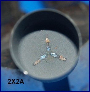
4HV Feedback Stella: I found a box of 2X2As under the stairs, so have sacrificed one to get a decent image of the cathode assembly for you. Comparing this with your angle plot, the rays may well be coming from the oxide cathode.
The misalignment of the cathode occurred while breaking the glass…The anode bell is strongly attracted to a magnet – perhaps a nickel alloy. The screening disk is also magnetic. EDIT: I’ve thought about what I have called a ‘screening disk’ and now think it is a heat shield to protect the glass seals from radiant heat.
In an amplifier, one would think of it being an EMI shield, but not in a diode power rectifier like 2X2. The bright reflective surface of the disk supports this interpretation.
Here are a few pics with the cathode, copyright Stella P.:


Here is one with the tube in operation, showing the hot, glowing “cathode” caused by electron bombardment:


and while the tube is glowing inside , here are some outside results:


First picture: an audio system IR remote while illuminated by the 2X2 tube
Second picture: a hardware password key
Third: a camera IR remote
4HV Feedback Stella:
There is an on-line X-ray shielding calculator for lead and other common materials run by the University of Dundee here.
There is a Constant Potential X-Ray Device Dose-Rate and Shielding Calculator at the RadPro site here.
and a dose-rate/distance Inverse Square Law calculator here.
Minerals which fluoresce with short wave UV will often fluoresce with X-rays.
This table distinguishes between short wave and long wave UV induced fluorescence.
Mineral UV Fluorescence Colors – Summary Chart is here.
I’d say that the first difference between the 2X2 and shunts like PD500, 6BK4B but also 6LJ6A etc, is the target geometry/position.
Instead of having a bottom, small sized filament, the 2X2 comes with an inner, rod like, central / very conveniently placed filament, covered in that white oxide that seems to help a lot – I believe the following features result from this:
– uniform emission with less shadows, when placing the tube at 45degrees the resulting images are well illuminated
– no electron beam focal points that would melt/puncture the filament if it was to be struck directly
I will capture a few close-up pictures of this glow, next time I power the tube.
4HV Feedback Stella:
The external diameter of the anode bell is 20mm.
The very slightly elevated and rough spot welds on the inside top of the anode are a possible field emission source.
According to Lederer,* cathode oxide coatings consist of mixtures of any of barium, strontium, calcium, and zinc, with mixtures of barium and strontium oxides being by far the most common.
A glance at the characteristic spectra of these four elements suggests that with Va = 40kV only a barium-containing target will emit X-rays energetic enough to escape through the anode bell and the glass envelope. Increasing the anode voltage from c. 38kV to c. 55kV will increase the output fluence of the barium target – the quantity of rays – but will not increase their penetrating power at all. Increasing Va to 65kV will produce little significant increase in penetration, as the graph makes clear. But the extra energy imparted to the electrons will be dissipated as heat in the fragile barium target, and very likely ruin it.
Strontium target: feeble bremmstrahlung and main peak below 15keV
Calcium target: assorted weak peaks over 20keV – a possible contender, but not very likely.
Zn target: feeble bremmstrahlung and peak below 10keV.
Now if you were to gradually reduce the tube voltage to 30kV, if there was a sudden fall in X-ray output once those Ba peaks are past, it would support the barium hypothesis.
The light source may be due to incandescence, as of calcium limelight.
Field Emission is a type of quantum tunneling which occurs at points of very high charge density – as in the needle and flat plate type of cold cathode X-ray source. The needle model goes right down to the nano-scale, with field emission cathodes made of carbon nanotubes now being used in sub-miniature X-ray sources the size of a grain of rice.
Notice strong shadows of the weld spikes in upper right quadrant of photomicrograph below:
x40 new
Here are photomicrographs of the anode bell coating at x80 and x200.
x80. Notice volcanic crater with three gas vents in the upper left quadrant. Also diagonal fissure below it.
x200
Note gold-coloured inclusions of unknown significance new
Cathode oxide coat x400 showing unknown inclusions – presumably manufacturing contamination.
The cathode tube, and its supports, are made of a magnetic metal. The damage to the oxide coat was done by Spencer-Wells forceps.
Cathode bare metal tip
The tungsten-molybdenum alloy heater is insulated with either aluminium oxide – aluminia – or beryllium oxide – beryllia – HAZARD! – but may contain small quantities of other refractory materials necessary to the coating process.* The 2X2As folded heater design was simpler and less expensive to produce than the double helix kind. The rust-coloured markings suggest the presence of iron.
* Shaw GR, Shardlow LR, Heaters & Heater-Cathode Insulation, Vacuum Tube Design, RCA, Privately Printed, 1940, p. 24 et seq.
*Lederer, LE, Filaments and Cathodes Part II, Lecture 2, Vacuum Tube Design, p.11 et seq. Privately printed, RCA, 1940.
From looking at your results, the tube seems to have two point sources inside it. It would be interesting to get a pinhole camera picture of them.
I think the dark ring discussed earlier can be explained by the variation in thickness of the anode bell normal to the direction of the X-rays.
It’s one thing to use a pinhole to image the anode spot of, for example only, a dental tube 70kV/7mA with a dose-rate of 1.5E+004 Sv/hr across the entrance to a pinhole 3cm from the target, (of which, say, 0.1% transits the pinhole) and another to form an image with the tiny fluence of a 2X2A in cold cathode mode and a few tens of microamps of current @40kV. Moreover, a dental tube’s roughly conical beam is highly directional, while Radu’s experiments suggest that the 2X2A output tends towards the isotropic, with only a small part of its X-ray output available for image formation on a plane surface.
As to the dark ring, I first thought the same as you – that it was the shadow of the anode wall cast by a source coaxial with, and below, the anode bell, but Radu’s subsequent experiments suggest a multiple or disseminated locus of emission.
I am now wondering whether a slit formed from two razor blades might be able to form an image from which further deductions could be made.
This getter retaining grille is spot welded to the underside of the heat shield, and from an X-ray source perspective suggests the possible existence of additional elements with their own characteristic radiation to add to the output spectrum mix.
The triangle of material missing at right in this macro image of the heat shield was clipped off for destructive testing.
This image at x40 suggests the presence of a once liquid metal on the lips of the perforations.
Here at x80 I am still not certain if what we are seeing on the perforation lips is metal that once flowed, or just an artefact of the punch perforation process.
2X2A Crystal formation in getter grill x20
I wonder what these crsytals are. And the white inclusion, third row up from the bottom, third row from the left, that looks to be part of a different crystal system. Could they have formed only once the glass envelope was broken and air was admitted?
And then there’s what looks like a piece of wire, partly occulted by the crystals, and which must be some kind of contamination, perhaps at the manufacturing stage. An ultra fine wire it would have to be too.
Funny how I completely missed all this before, but that’s what comes from forgetting that it’s just as easy to get lost in an infinitely small space as in an infinitely large one.
2X2A getter grill single crystal bright field technique x200
Tentative interpretation: this is a dynamic, evolving system which is still developing. Krzysztof Penderecki
Lederer, in Contact Potential, Pumps, and Getters RCA, 1940, describes the use of barium-magnesium and barium-aluminium alloy getters, which he says “are brittle at room temperature. It is customary, therefore, to pulverize the alloys and compact the powder into small pellets on a pill press.” This description fits the 2X2A case perfectly, as there is a pill shaped pressing on the upper surface of the heat shield above the grill.As for watching the crystal grow, I have done just that, but not intentionally. I ran a 100 image stack at x1000, which took about ten minutes, but the output image had odd artefacts which you’d only expect to see if the subject had moved during stack compilation. I didn’t think that much about it, because it’s difficult to avoid vibration altogether at that magnification, making image synthesis problematic for someone with only very basic equipment, and even more basic skills. barium hydroxide octahydrate Ba(OH)2·8H2O is a likely candidate for the crystals – an extremely noxious, toxic substance – though I suppose it could be a complex of barium and magnesium, or barium and aluminium, for all I know.


13. Feb 14, 2011: Other vacuum tubes
Note: Again, I will be using several vacuum rectifier tubes or shunts, in inverse polarization at 50KV.
1) The Russian V1 0.1/30 . I have 4 of these. Here are some results:
TEST A: Tube in vertical position, fluorescent screen in close proximity (2-3cm):


The first pictures shows the setup,
The second and forth pictures show the fluorescent screen while the tube is applied 50KV in inverse polarization (no fluorescence),
The third picture shows a closeup on the tube, while running.
Notice the glass blue fluorescence, seen on other X-ray tubes, is missing! ; instead the bottom of the tube is strongly illuminated. One of my 4 tubes, has a small metal blocker right under the anode bell . Not this one. Wondering why, I turned the tube in horizontal position:
TEST B: Tube in horizontal position, bottom oriented towards fluorescent screen:


Results? Nothing on the fluorescent screen, after 15seconds of exposure (the same parameters as for the 2X2).
The Radex 1706 was picking up small amounts of radiation. Placed at 3 meters : 0.42uSv/h
The DY86 . I did some tests with this kind of tube some time ago. But now I have another one that seems different. Applying 50KV created a lot of flashovers, a nice show of sparks, putting the tube in real danger. Some tape fixed the problem. Here are some pictures:


First picture: The tube connected to the supply is covered in sparks
Second picture: Using some tape to better insulate the tube’s terminals
Third picture: Some nice fluorescence on the screen, comparable in intensity (energy level) with that produced by the 2X2. Of course, the field is distributed in a narrower shape (among other disadvantages like small tube size: thermal and insulation problems, small vacuum volume inside possible cause for parameters changes in time, etc).
4HV Feedback Les:
OK the intensified pinhole camera works fine.
First off we have an image of the focal spot of a small dental x-ray tube (below).
Note, the resolution is good enough that is is obvious the spot is rectangular, corresponding to the spot etched to the anode face
So since I am waiting for KWTubes to send me the 2X2’s I thought I would abuse a PD500. It is a poor x-ray emitter, and when driven in field emission mode, emits most of its radiation from near the base of the tube.
Due to the low flux this required a 15 sec exposure of the image intensifier screen.
Note the circular structure with two lines either side. This is the end of the heater coil, with metal grid supports either side (hidden visually behind mica end plates!). There are many other emission points from various metal parts near the base of the tube.For future photos, I will take an AVI and stack the frames, and see if a longer integration period will yield a clearer image.
Approx 45kV. (no current measurement I’m afraid, but most assuredly very feeble). It is a really unstable tube driven like this, with occasional x-ray flashes as vacuum breaks down. It was really quite interesting to watch through the pinhole camera.


14. Feb 20, 2011: 2X2 CCCP vs. US version
Note: 4 variants of the 2X2 Tube has been used. The tubes stand in vertical position. The camera has been set on a tripod, with unchanged parameters (same focus/exposure time/etc). All the tubes has been powered up in inverse polarization, using the same potential difference.
Objective: compare the x-ray emission output by using the fluorescent screen
The tubes used:

From left to the right:
The russian 2X2 (that I’ve used several times in this thread).
Three american 2X2 variants, the forth appears to be the oldest (manufactured in 1954)
In the same order, here are the results:


The Russian 2X2 emits the most radiation. Actually the X-ray output a few times the output of the other tubes. An impressive difference.
The setup has not been changed, extra care was taken when replacing the tubes not to change the distances / fluorescent screen position from the camera, so differences in the emission field can also be observed.
The last 2X2, from 1954 seems to have 0 x-ray output (vacuum inside lost because of age? ).
15. Feb 20, 2011: Targets
Note: the camera has been brought dangerously close to the setup, to take photographs of the electron targets:
1) In normal polarization the source is the normal central cathode , and the target the inside of the electron bell
2) In inverse polarization, the source is the inside of the electron bell, and the target the oxide cylinder covering the filament.
The 1954 American 2X2, used in inverse polarization:


Remember, this tube has very little (if any) x-ray output. Since I used the fluorescent screen for detecting radiation, I used no dosimeter (Radex 1706) in this test scenario. The third picture has the exposure reduced, so you can see the oxide tube getting hot-red because of the electron bombardment. No other component inside the tube seems to be targeted (not even the wires supporting the oxide tube).
Another American 2X2, in inverse polarization, with the oxide tube glowing because of the electrons:


An now, the last tube again, in direct polarization. In only a few seconds (aprox. 6 seconds), the anode bell is incandescent, because now it becomes target of the electrons emitted by the central cathode:


On the other hand, my tests showed that the Russian 2X2 doesn’t get incandescent not even after 15 seconds!
Luckily my camera survived the dangerous proximity of the setup, and no arc-overs occurred to it.
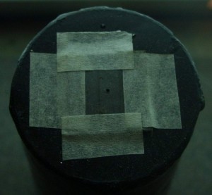
16. Feb 20, 2011: Pinhole camera – a Paradox?
Note: Using the Russian 2X2, a sheet of lead has been placed in front of the tube, in vertical position. In front of the hottest x-ray emission zone, a pin hole has been made in the lead sheet. The distance between the tube and the lead sheet is 6 cm. On the other side, at 4 cm distance, the fluorescent screen has been placed. So the distance between the fluorescent screen and the tube is a total of 10cm.
The camera has been brought close to the fluorescent screen and focus attempted using the super-macro setting.
The setup:


Based on my previous experiments, I would have expected the camera to record a filled spot (since I assumed we have an uniform SINGLE x-ray emitter source – the central oxide bar). Instead… :


The images have been enhanced in software (With the last image pushed to noise levels to get the maximum out of the projected image). Now a lot of damage on the CCD (random pixels) also becomes visible.
Comments:
If I’m not wrong, it appears there are 2 points of emission in horizontal plane? If yes I can only think of the glass walls (left-right).
4HV Feedback Les
My 2X2’s turned up today, thanks to Gintaras!
So first off I had to test this out! The radiation this little tube produces is totally amazing! It will actually conduct mA’s if pushed hard enough, but of course this will quickly destroy it.
So I set up the pinhole camera, and produced a pair of images that settles where the radiation comes from.
Nearly all of the x-rays come from………………the heat shield, making the edge of the anode bell the most likely emitter of electrons. (I had had incorrectly surmised the entire surface was emitting electrons in the direction of the heater)
The photo below is a pinhole image looking down onto the heat shield.
The top surface of the shield is obviously a bright emitter of x-rays. The black structure in the middle is the heater and cathode support obscuring the x-rays.
Note underneath the heat shield some of the glass support can be seen, (note also the hole for evacuation!) There are slots cut in the heat shield, so electron beams make their way through, and impinge on the glass support, causing parts of it to emit x-rays.
Below is another view of the 2X2 this time looking up towards the underneath of the heat shield.
Note the original heated cathode is a poor emitter of x-rays, and is actually emitting less x-rays than the glass support is! Note also that the underside of the heat shield is visible since the x-rays produced at the top surface make their way though.
The radiation on the underside of the shield must inevitably contain the characteristic spectra of the metallic elements used in the shield, including the pressed barium alloy ‘pill’, in addition to any target transmission shoot-through.


The shielding plate seems to be a good answer for several observed aspects:
– why do we get two concentric shadow rings, when the tube is placed with the anode perpendicular to the fluorescent screen (one would be the anode cap, the other could be from the anode bell)
– the uniform distribution of the x-ray emission, all around the tube
– the good performance at 45 degrees
– the different performance between the Russian variant and the USA variant (that doesn’t have a heat shield)
Les’ images with some additional software enhacement:


Still if the shield is a target for the electrons coming from above, how come we get so much radiation in the shield’s plane?

4HV Feedback Stella
I think perhaps I should have added a few words of explanation to the graph.
You will notice that at 50keV, there is significant radiation at 90° to the electron beam, but at 500keV the bremmstrahlung follows the direction of the electron beam much more closely. i.e. the tendency of the bremmstrahlung to follow the electron beam direction is energy dependent.
Now, if you have 40kV on your anode, about 1% of the X-rays produced will have an energy of 40keV, and all the rest will have less, down the lowest energy that can transmitted by the glass envelope (say 15keV) tending to become more and more isotropic with decreasing energy.
And to these increasingly isotropic bremmstrahlung can be added the isotropic characteristic rays of the elements in the target.
Your observations about heat dissipated in the anode seem to confuse X-ray energy with tube current and with fluence. You could have 100kV across a micro field emission tube which drew but 1μA, for a total power of 100mW. It would emit a tiny amount of 100keV rays, but their fluence – quantity of photons per square metre – would be very low indeed, and the tube would not get significantly warm.
Conversely, you can find Be window XRD tubes with just 10kV on the anode that gobble up 1kW or more and need high pressure water cooling.
On a separate note: FILTRATION
Filtration with Al, Cu, or Ag foils may improve the resolution of the pin-hole images.
Uzzors2k:
This is amazing! I’ve been following this thread since it started, and have to say I’m impressed by what you guys and gals have discovered. I’m tinkering away at my own setup right now, and hope to try some American 2X2A tubes I have.
Your pinhole images are fascinating Leslie, you’re using an intensifier tube to see this if I’m not mistaken? I’m interested in the details of the pinhole itself too. Reading about pinhole cameras it would seem we need a micrometer sized hole to get focused images, if using a practical focal length.
Oh, and to help aid visualization of the x-ray source, here’s Radu’s enhanced images beside Stella’s heat-shield pics. The detail is incredible!
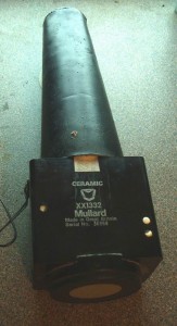
Les:
Its a GenII image intensifier tube with GADOX scintillator bonded to the face plate, like my fluoroscopes. The pinhole is 0.05mm diameter. Micron sized would be better, but even with a system gain of around 40,000 very long exposures would be needed.
The apparatus consists of one of my very sensitive x-ray Fluoroscopes described here, (except this version uses a Generation II tube),and a lead pinhole camera assembly.
An 8 inch long truncated cone was fabricated from lead sheet. The tip of the cone is flat, with a large hole drilled in it to permit mounting a pinhole of any size. . The pinhole is about 0.05mm across, and was made in a separate thin piece of lead.
This is simply mounted on the front of the fluoroscope, and pointed at the x-ray source. The output screen in viewable in real time to dark adapted eyes, but the digital camera requires a 15s exposure to produce a bright enough image from the screen.
The cone of the pinhole camera is made so long as to permit some decent magnification of the x-ray sources.
For those interested in the pics of the pinhole camera (its really not that exciting to look at though). Above is the lead cone that fits onto the intensifier assembly. The tip of the cone is truncated to mount the pinhole. The pinhole is made from a thinner piece of lead, and is simply taped in place. The intensified fluoroscope is a Mullard (now Phillips) XX1332, with Gd2O2S:Tb scintillator bonded to its large 50mm diameter faceplate. The cone sits neatly on the front. I still need to make a suitable mount for it, so I can set it up on a tripod for long exposures


On another closer look, the shield might be affected too:

Here is a little experiment. Pictures are self explanatory:


It shows that we get the same circular shadows if we place the source of light where the shield is.
So in case of x-ray emissions, this would produce the 2 concentric shadows we’ve seen on the first tests with the 2X2.
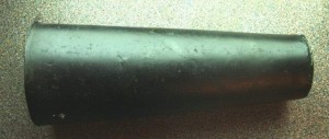
17. May 5, 2013: Russian GP-5 vs Russian 2×2
I remember Linas mentioning the GP-5 tube. Indeed it looks like a good candidate for the purpose of this topic, given its size and solid construction:


It does produce x-rays when energized at 50KV in reverse polarity, but nothing compared to the 2X2. Here are some images:
GP-5 in normal polarization (+50KV to anode)


The first two pictures are original, as recorded by the camera.
The third picture was enhanced in software with a Gamma Correction factor of 3 (increased exposure/luminosity)
The forth shows the same setup, but having a Kodak intensifier paper cylinder wrapped around the tube. Software enhancement, with the same gamma factor of 3. No green fluorescence can be observed.
Exposure settings are: 2nd picture: 10s/F5.6/ISO 500 and for the 4th picture: 13s/F5.6/ISO 800
GP-5 in inverse polarization (+50KV to the cathode)


2nd picture is a gamma corrected variant of the first, factor of 3. 1st picture settings: 13s/F5.6/ISO 800
Here is the tube with the Kodak intensifier screen:


2nd picture is a gamma corrected variant of the first, factor of 3. 1st picture settings: 15s/F5.3/ISO 640
Some green fluorescence is visible.
And here is the 2X2 tube, place instead of the GP-5, in the same exact setup:


2nd picture is a gamma corrected variant of the first, factor of 3. 1st picture settings: 15s/F5.3/ISO 640
Increased amounts of radiation are being produced.
Conclusion: at 50KV, the GP-5 produces some x-ray emissions, but nothing compared to the 2X2.
2X2 energized at 50KV in reverse polarity
See the impact zones on the heat shield and glass.


4HV Feedback Stella:
Interesting experiments, Radhu, but the results are no surprise.Let us think about the basic differences between 2X2 and GP-5.
2X2 was designed as a high voltage rectifier diode during the Second World War. It was designed to rectify RMS max 5.5 kV, and 12.5 kV PIV. This means that when operated within its design range, the soft X-rays produced by electron bombardment would be completely stopped by the glass envelope, so no X-ray shielding was included in the design.
By contrast, the Svetlana GP-5 was designed as an EHT shunt stabiliser triode for colour television service. Its maximum anode working voltage was 30 kV, so effective X-ray shielding has been built into the design, as we see clearly in your pictures. The envelope glass very probably contains lead or other heavy elements to attenuate radiation leaking round the shield. As colour TV broadcasting did not start in the former Soviet Union until 1967, I would judge this valve to have been designed after the significant X-ray hazard of earlier American EHT stabiliser triodes like 6BK4 (1955) was well known. So your experiments have proved the superiority of Soviet engineering! 🙂
18. Oct 20, 2013: Conclusion
Once the central of attention of all electronic applications, the vacuum tubes, the top edge devices of the thermionic era, have been well known for posing radiation risks, for being capable of emitting x-rays when malfunctioning or when overovolted.
This article has shown the details behind this process, focusing on a particular device, the Russian 2X2 vacuum tube, that not only puts out copious amounts of radiation, but as shown above, the radiation field can be produced in such a way that we can use it to obtain reasonable quality radiographs of small objects.
The phenomenon has been demonstrated, explained, but we came up with useful applications harvesting the unwanted side effect of this high vacuum tube. Thanks go to the 4HV.org community, who’s help was invaluable to the success of this research work.