

This article is the sum of multiple research results, and it was edited across almost one year. You can use the menu below to jump to the relevant parts, or start reading it in chronological order (newer posts are at the bottom).
Progress summary:
2012-05-25, Geiger Dosimeter (video)
Digital Geiger Dosimeter:
2012-09-02, Digital Geiger Dosimeter
2012-09-11, Update on Atmega8 Timers and Counters
2012-09-15, Update on Issues with Timer1
2012-09-16, 400V Inverter Instability Issues fixed
Shaping the uRADMonitor project:
2012-10-11, Some enc28j60 remarks
2012-10-12, Atmega168 up and running, first online beta test open
2012-10-18, Sensor board ready; Signal Capacitor (C7) comparison
2012-10-19, Device enclosure box ready
2012-10-20, The results
2012-11-11, Updates
2013-07-26, Maintenance updates
2013-08-05, Watchdog implemented: no more manual restarts!
2013-10-29, Major upgrade: new sensors added
2013-12-01, Fixing a few issues
2013-12-10, Compensation capacitor
May 25, 2012 – Geiger Dosimeter 3.2
Here’s a video featuring version 3.2 of my geiger counter circuit, tested with several tubes:
I did some additional changes to my v2.0 simple geiger clicker, to improve it even further. See below the new 3.2 circuit diagram followed by some explanations. The ExpressSCH circuit diagram is here.

1. The High voltage supply
The goal is to have a counter working at 3V (2xAA batteries) with very little power consumption. This excludes using 555 timers or other fancy ICs. My choice is a feedback based one transistor oscillator. It provides 400V output, for 100mA at 3V.
I am using a ferrite core transformer, 17 turns for primary and 17 for the feedback coil, with 0.2mm CuEm wire. The secondary has 550turns with 0.1mm. The oscillator is operating at a frequency of aprox. 23KHz.


The transformer’s output is rectified and multiplied by the 3 stages multiplier (10nF 1KV capacitors / BYV26E fast diode).
2. The voltage regulator
The geiger tube requires very precise voltages to operate. For this setup, I need to get 400V from this supply, regardless of variations in the input voltage (weak batteries, etc).
This task is achieved by the string of Zeners and the Q2 transistor. When the voltage produced by the multiplier exceeds the Zener threshold , the Q2 transistor opens, and pull down the base of Q1, stopping the oscillation. By doing so, the output voltage remains at a constant level, that equals the Zener threshold. The multiplier must produce a little more than the voltage that triggers the zener string.
3. Connecting the Geiger tube
An essential component is the Anode resistor (10M in my circuit). The resistor’s minimum value, for any given tube, is specified in the datasheet, but it is a good practice to use a higher value where possible.
The anode resistor is responsible of the following:
– reduces the anode voltage when the tube is conducting. This allows the tube to recover after the discharge. Without this, the tube would conduct continuously and would be destroyed quickly.
– it limits the current flowing through the tube, leading to longer tube life
– it has an effect on the plateau length, a lower value of R1 gives a shorter plateau length [1]
For the pulse signal, there are two connection options:
Anode signal connection This type of connecting is not preferred: – at switch on, a high voltage transient will be fed to the measuring circuit, resulting in additional protection requirements. – noise in high voltage rail, will be fed to the measuring circuit via R3. |
Cathode signal connection Centronics’ “Geiger tube theory” recommends using the cathode connection whenever possible [1]. R2/R1 should be 1/45, taking into account a large value for R1 as explained above (eg. 10M). |
4. Measuring circuits
With the cathode connection, the measuring circuit’s task will be to count and evaluate the positive pulses connected at the cathode resistor R2.
For the circuit v3.2, we will collect the signal, in point A, at the emitter of transistor Q4. Here is how the pulses look like:


I was able to successfully connect it to my CD4026 digital counter , as seen in the video. It works great as a counter showing the individual pulses.


The final setup for v3.2:


References
[1] CENTRONIC , Geiger Muller Tubes, link
September 2, 2012 – Digital Geiger Dosimeter v3.3
For this update, my goal is to go digital. I need to use a microcontroller to take care of everything: regulated high voltage invertor using PWM and ADC voltage feedback, a timer to count seconds, a counter for tube pulses, and finally an Ethernet interface to export data via a network.
The result will be an Internet connected Geiger Counter, collecting various data and provided graphs over large periods of time.
I am planning to use the Atmega8 microcontroller, and push the little program space to its limits.
The Ethernet part is complete, and has been presented here: Atmega8 and enc28J60 for Ethernet support.
…
A few hours later, I got a timer and a counter working on the Atmega8, so now I can measure time and also count the pulses coming from the tube . This gives us the dose measured in cpm, sweet first results!

All’s left to do is to integrate the HV supply to the uC’s circuit, using a simple PWM driver with feedback.
September 11, 2012 – Atmega8 Timers and Counters
I did some progress on the HV inverter needed for the tube. I will have to stick to 400V . The project will be boxed and placed on a remote location outside. From there it will collect data and build various graphs. I have the geiger couter , a temperature sensor, a humidity sensor and a light intensity one. If anyone has other ideas on additional hardware that I should pack in, now it’s the right time to say it.
A future project might be having a geiger counter dosimeter with multiple tubes, etc, and a nice LCD display to output the data. Or even some kind of “lab-tool” for testing the tubes.
Multiple pulses happen, and would be good to measure them correctly. This is called discrimination. The following pics show a few such pulses, as recorded with the oscilloscope:


A little update on my progress. I managed to put the microcontroller software together. As I am using an ATMega8, I opted for the following:
– INT0 interrupt to count all incoming pulses on raising edge. I do not have any discriminator yet.
– T0 timer to count passing time. I configured it to generate 1.024ms events, so 976 such events will count for a second.
– T1 timer to generate PWM signal. I got it to accept variable frequency and duty factor. I will probably go for 40KHz to drive a little 2n2222 transistor that pumps the primary of a small ferrite core transformer:
![]()
I noticed that without any protection, I will get voltage spikes in the microcontroller circuit, measured at PB1, where the PWM signal is provided (spike backs from the ferrite transformer, most likely). So a fast diode, used as snubber was needed across the primary of the small ferrite transformer . See the following images, first without and second with protection:


I still have some issues:
1. I almost used all the program memory available for the atmega8 and still need to code some additional routines. I might be forced to move to a more capable uC. I’ll try to optimize and reduce code before I have to do anything like that.
2. There’s some interference, between the timer1 PWM, with the ISP interface that handles the Ethernet module:

Because of that, the microcontroller hangs at some times. This is extremely annoying considering I need to have this project as a remote box running for large periods of time.
Some of the factors that are causing this:
– bigger duty cycle (timer1’s PWM)
– some delays in the software’s main loop
– reading ADC ports : I need to read them for sensors, and for checking the inverter voltage. The inverter produces roughly 400V when powered on. The voltage is read using one ADC port. If the voltage is less then required, the duty cycle is increased. If the voltage is bigger then the target set, the duty cycle is decreased.
I will find the cause of this eventually. As it is now, the software opens a TCP/IP socket on port 80 where it exposes some HTML content. So it is a small WEB Server, where you can see some details such as number of times it was accessed, pings received, time since startup, number of counts, CPM, and the dose in uSv/h , estimated for the SBM-19 tube.
Instead of this functionality, which I needed only for testing, the final software needs to work as a client, not a server. After computing all the sensor data locally (including the radiation dose), it will send it online, to a script running on my webpage. So instead of opening a port and waiting for incoming connections, the idea is to have it open a connecting to my server and export the data there. Easy. I believe the timing issues that currently lock my uC from time to time, will be resolved, as having an ongoing connection instead of keeping a port open is better.
Here’s a photo showing the software run on a test board, with a LCD hooked up for showing the dose in uSv/h 🙂

September 15, 2012: v3.3.100 – Issues with Timer1
I decided to set numbers for these updates to help organize it better. So this is 3.3.100.
I’ve been working on the inverter. It seems I’ll be able to have it run in a very wide range of values. This is thanks to a new ferrite core transformer that I made: A22 ferite core (it is really small, 1cm diameter), 16 turns primary with 0.2mm wire, and 600 turns secondary with 0.1mm wire. It is driven by a PN2222A generic transistor, using the 5V rail.
The output is fully rectified using 4 fast diodes set in a bridge. No multiplier required! 🙂
I made some tests with various frequencies. Here are some results, yellow/CH1 is at the PB1 pin, while cyan/CH2 is the inverter output:
40KHZ, duty:16% 396V, duty:35% 792V


20KHz, duty:10% 396V, duty:15% 616V


10KHz, duty:1% 200V, duty:16% 768V


I will probably choose a 20KHz frequency to set it out of the audible spectrum. The driving signal seems a little distorted, as I am still getting some spike backs from the ferrite transformer. I should fix this as well.
I’m still having issues when using the enc28J60 code together with the Timer1 PWM code. So either I have the Ethernet interface, either I have the PWM signal for the HV inverter. Sometimes it works, but not very stable. Here is the current circuit diagram, version 3.3.100:

I got some interesting results, and good news on the same time. Using a 8x prescalling when setting the Timer1 PWM, seems to allow the code to work together with the enc28j60, as expected. So this seems a good starting point, too bad I don’t know the exact cause of these issues. Code for enc28j60 is rather complex , already.
September 16, 2012 – v3.3.101 – 400V Inverter Instability Issues fixed
I finally fixed the instability problems, the network module / PWM interference, and most of the issues I’ve mentioned before.
The problem was improper filtering in two key points:
1. The inverter’s driver needed a little protection from those spike backs. For this I used two resistors at the inverter’s driver base , and a little choke between the transformer’s primary and the positive rail. This solved the spike backs, CH1/yellow at PB1, CH2/cyan inverter output:

Notice the PWM waveform still seems a little shaky at the top.
2. Voltage regulators (5V and the 3.3V), needed a few electrolytic caps


Now the PWM looks much better (have a quick look to the previous oscilloscope screens), and the circuit performs as expected, seems like the Ethernet module was greatly influenced by all the variations and improper filtering.
Here is the new schematic, v3.3.101:

This works great, finally! I am able to adjust the duty cycle and get perfectly regulated high voltage needed for the geiger tube. The voltage feedback reading with ADC will be used to adjust the duty cycle automatically: increase it if voltage is less than 400V (or any other target voltage), or decrease it to lower the output voltage, if more than 400V is being generated.
Compared to V3.2, the ripple is almost zero! See the two photos below:


The first, shows my version 3.2 inverter output, that uses a NPN oscillating transistor in an Armstrong oscillator, and a feedback mechanism constructed with zenner diodes set for 400V, that triggers an oscillator-blocking second transistor. Illustrated as trace for CH1 – yellow, set for 400V.
The second shows the output in 3.3, fully rectified and produced by a a precisely calculated PWM signal. See the CH2, cyan trace, set for 350V. That was only for testing, as the feedback mechanism now sets the voltage for 400V.
October 11, 2012 – Some enc28j60 remarks
For now just a few observations:
The ENC28J60 will work without the 74LS125N buffer just fine, assuming you don’t have other devices connected over SPI. This simplifies things a bit. I also did minor changes on the ENC28J60 code and now the stability is much improved. Can be seen here.
Now a bigger problem is that I’ve consumed most of ATmega8’s flash memory, and still need to do some additional programing. This forces me to move one step higher , to the Atmega168 microcontroller, featuring 16KB of flash memory, instead of ATmega8‘s 8KB.
Still , it will be possible to use the Atmega8 for a standalone dosimeter, with 1 tube, LCD screen, and built in high voltage power supply. But not if we want the ENC28J60 ethernet interface, like for this project.
October 12, 2012 – Atmega168 up and running, first online beta test open
Some news. Got the new little board up an running, featuring an Atmega168 micocontroller instead of the original Atmega8, because the TCP/IP stack was already consuming 7KB of our Atmega8’s 8KB total flash memory. Besides the network stack, I need to drive the HV inverter, check the HV value for regularization, count the time and the pulses, do some logic on those values, and so on… additional programming that would not fit in the Atmega8.
What should have been a simple task, since the 168 has the same pin layout like the Atmega8, ended up as a mess, wasting two days of my time. I will structure the findings and indicate the critical issues, in case others will walk this path.
In the end, it works… not yet in the final form, as I need to build charts and store the data, add sensors, and lots of bells and whistles, BUT, here is how it looks like:

The software computes a CPM value based on a 5seconds time constant and displays the corresponding Sieverts/Hour dose in regards to the SBM-19 Geiger tube characteristics.
The board is currently up and running for a stability test, and can be accessed over the internet, here (edit: test ended). Give it a run, and let me know what you think!
Issues migrating from Atmega8 to Atmega168:
1. Atmega168 will not work with enc28J60, unless you use PB2 for CS. Atmega8 did not have this issue, which cost me two days to figure out. If PB2 is not used, the Atmega168 will hang in enc28j60Init, when doing the first enc28j60WriteOp, because the waitspi(); never gets to finish.
2. Keep the code inside interrupt callbacks light: the T0 interrupt was computing some time related values, but also reading the ADC port for voltage regularization. This crashed my uC until I moved the ADC reading code to the main loop.
3. Keep the strings to a minimum, since the RAM is extremely limited. Buffer overflows are hard to debug on a microcontroller. So are the other memory related issues. Double check, triple check or rewrite the code differently.
…
 After 2 hours the device is still running with good stability. The absolute CPM given by my background radiation is 90 cpm . A very raw conversion to uSv/h, based on SBM-19 characteristics, would give us 0.18uSv/h. |
 After 15hours of continuous use, the device is still functioning well. Here is another snapshot of the web interface. What’s interesting is the absolute CPM, has dropped significantly. I wonder why. |
Here is the setup so far:


Circuit diagram, v3.3.103

The signal is processed by a small preamplifier, with the two transistors 2n5551 and BC558, resulting in a positive pulse of 50-100uSec and 5V amplitude, that is fed to the microcontroller’s interrupt INT0 pin: PD2.
…
After 42Hours it is still up and running, so I would say stability has been proven for this circuit, and I will stop this test here:

…
Update October 14, 2012
Some news: I managed to successfully initiate a Tcp/ip connection from the Geiger counter to a PHP script on this blog. It’s late now, but I have everything in place to start exporting data.
October 18, 2012 – Sensor board ready; Signal Capacitor (C7) comparison
I’ve completed the sensor board:


Sensors and microcontroller software are working together. This project was full of obstacles, almost every single step came with bugs and issues, but eventually my determination prevailed.
Finally , here’s the data received on my server, comments added after #
id=1 #this is a simple id, in case I will build more of these devices
cip=192.168.2.153 #the local device IP obtained by DHCP – no network config required!
vol=400 #the voltage on tube
duty=74 #7.4% inverter’s duty cycle responsible of the 400V produced – used in regularization
pulses=2463 #number of pulses counted since start up
s1t=22 #ds1820 sensor, this is temperature in degrees celsius
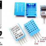
s2t=24 #dht11 sensor, temperature in degrees celsius
s2h=75 #dht11 sensor, relative humidity
s3l=19 #photodiode sensor, luminosity
td=0 #number of days since start up
th=0 #number of hours since startup
tm=16 #numer of minutes since startup
ts=41 #seconds from startup
cpm=72 #CPM for the last 5 seconds , just for debugging purposes
Note:absolute CPM would be 2463 / 16.6 ->148 cpm . a bit high I’d say
…
pulses=4166
th=0
tm=38
ts=11
absolute CPM after 38minutes: 109.63 cpm , it is getting closer to expected dose rate.
…
pulses=6323
th=1
tm=4
ts=1
absolute CPM after 1hour: 98cpm
Thanks to Stella on 4HV.org, I’ve changed the C7 Capacitor (see diagram 3.3.103) to a smaller value. As Stella kindly explained, “The larger the capacitor, the slower will be the rise and fall times of the pulse. I would have expected to see a capacitor of 20 – 100 pF here “, while I’ve used a huge 20nF capacitor!
This is now changed to a 33pF capacitor, and here is a comparison chart showing the pulse shape/length with three capacitors, while the tube is exposed to natural radiation, to a Am241 source, and to a Cs137 source:

The modification will show in the next circuit diagram update.
October 19, 2012 – Device enclosure box ready
Box is ready, completely made of PVC pipe plastic, after transforming a piece of pipe into a sheet and cutting it when heated:


I also created sockets, from the same plastic source, for the geiger tube:


The orange plastic is great, the finished box actually gives the impression of a very good quality plastic / case! Funny considering what materials I’ve used.
October 20, 2012 – The results
Final software adjustments have been made. A new SQL database has been configured on pocketmagic.net to receive the data from the online dosimeter. Box has been closed and sealed, then mounted outside my home. Drilling a hole in the outside wall allowed me to install the power and Ethernet cables.


Circuit diagram, v3.3.120:

3.3.110 2:07 PM 10/23/2012
SERVER/php:

- final data export script: public.php  . deleted clones

- standardization of export script parameters

- fixed interval: last value shown is last present value

- caching implemented and set to 2 min interval

- fixed bug with displaying last hour in chart

CLIENT/atmega168:

- s2 bug fix, for invalid >100 values

- luminosity computed in percents 0..1000

- time calculation fixed, g_nTimeMilis >= 960

- added isp external connector
November 11, 2012 – Updates
3.3.121 12:51 PM 10/28/2012
SERVER:

- added subdomain uradmonitor.pocketmagic.net

- fixed server downtime chart calculations: missing data time zones are skipped - the graph will simply jump to the next data available.

- added uSv/h

todo: add offline text if no fresh  (>5min) data available

- 3 digits added to values. back to 2 digits.

- added redicted in pocketmagic.net/uradmonitor to uradmonitor.pocketmagic.net

- limits set on the PHP script parameters: 30 for interval and 24 for integration
3.3.122 2:18 PM 11/02/2012
SERVER:

- debug now shows duty cycle too.

CLIENT:

- changed the R5 resistor , as the original burned out (poor chinese quality)

- recalibrated the inverter voltage feedback, by measuring the new R5 value.

- placed safety limits for upper duty cycle percent interval: the burned R5 caused a voltage increase up to 800V!! No other components were harmed.
3.3.130 2:14 PM 11/11/2012
SERVER:

- added new graphs: pressure (bmp085) and temperature 3 (bmp085)

CLIENT:

- dht11 sensor replaced with dht22

- bmp085 sensor added

- new sensor PCB board

- new sensor board sun shield

- additional code for the new sensor and i2c bus connectivity

- atmega168 replaced with atmega328p
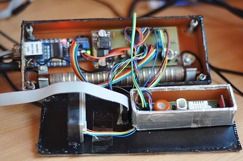
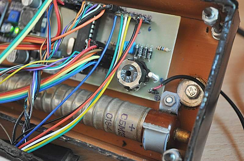
Photos of 3.3.130 update:


Circuit diagram 3.3.130

3.3.131 6:28PM 12/10/2012
SERVER:

CLIENT:

- time computing code updated

- dht22 issues below 0 degrees, because of issues in CRC computation
July 26, 2013 – Maintenance Updates
From the last update in November, there have been some changes, mostly upgrades and fixes. To name a few: the tube voltage is set to 375V, so the duty cycle goes down to only 5%, some changes in the Ethernet code, and most important, the entire firmware rewritten as C++ code with classes.
August 05, 2013 – Software watchdog implemented
From time to time, I had to manually restart the uRADMonitor station because it was freezing. While working on the global radiation monitoring network project, I designed a network enabled board, that also featured an LCD, so this setup made debugging on the original uRADMOnitor code a lot easier.
Using this, I was able to pinpoint several issues in the networking code, but also implement a 5 minutes auto-reset watchdog, in case something goes wrong. This is a software based watchdog mechanism, to ensure maintenance free functionality and 24/7 uptime. Need to see if this works as expected, during the next few months.
October 29, 2013 – Major upgrade: new sensors added
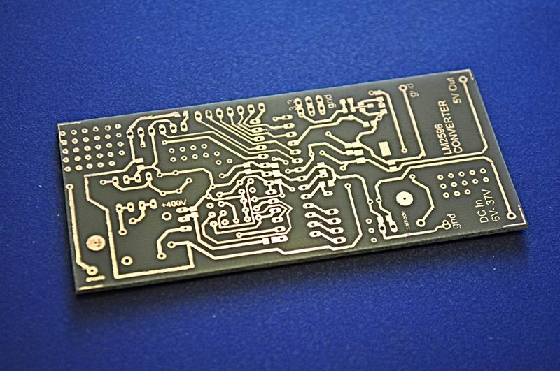
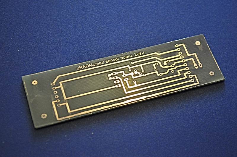
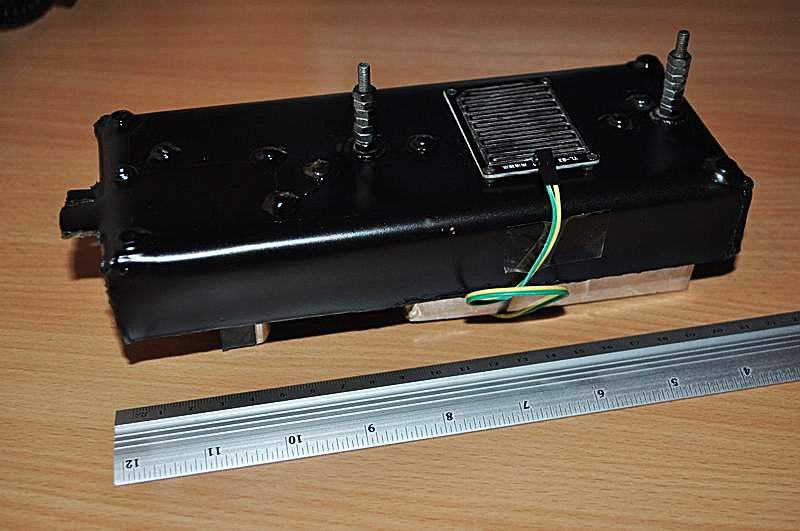
One year after I created the uRADMonitor device, it was time for a major upgrade. So how to say “Happy birthday!” better, then by adding some extra hardware to the device, and making the existing one better. So I started by painting the case black, using a spray paint. Then it took me one day to design a PCB for the device, and another one for the sensors board.
The plan was to add three additional sensors: a MQ-9B combustible gas sensor for air quality, a rain sensor and a SHARP GP2Y1010 optical particle sensor.
The boards were done with the toner transfer method and came out nicely:
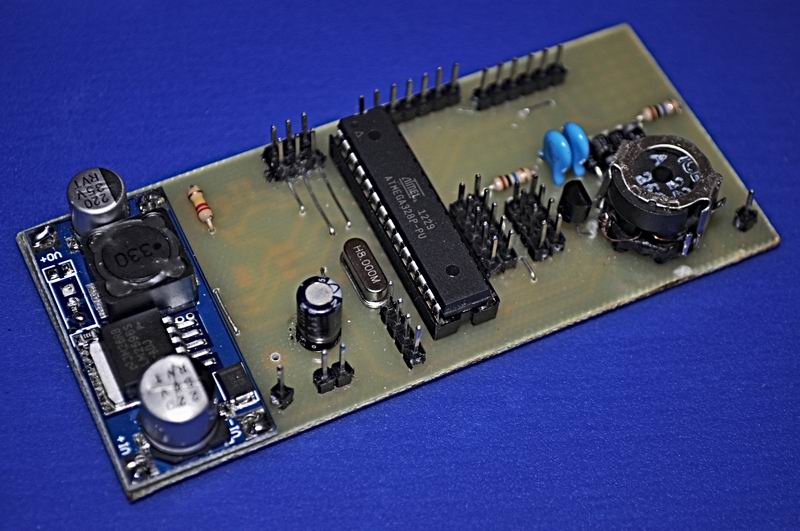
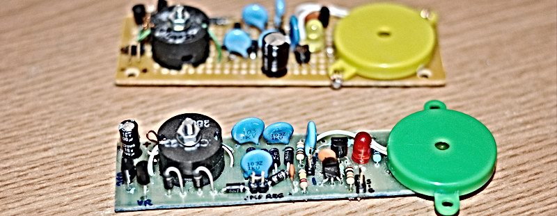
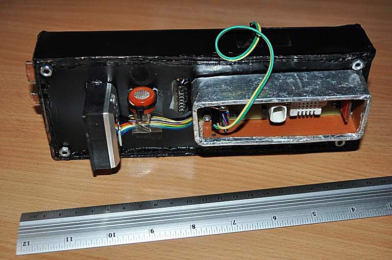
When I look at the old board, I’m surprised uRADMonitor worked so well during the last year:
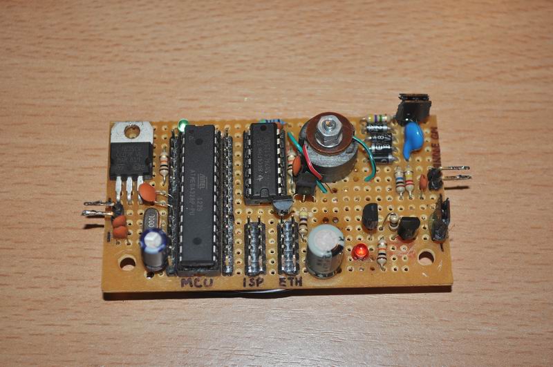
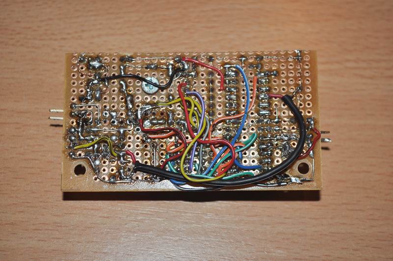
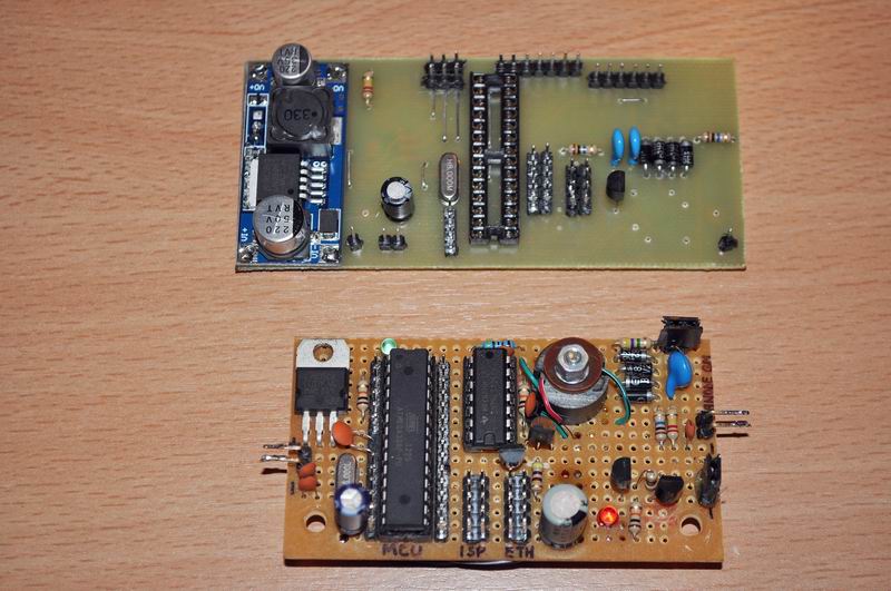
The last picture shows the new board (top) with its brand new PCB compared to the old board made on a test PCB (with tens of floating wires). I’m glad that I finally had the time to make a proper board! All done manually.
After putting everything together I had tens of issues to fix: I changed the crystal to 8MHz but not the software, the jumper wires for the sensor board were wrong, the code had issues and the new Vref was now 3.3V and not 5V. Oh yes, and a transistor was mirrored because of the wrong Eagle symbol. Luckily it was an easy fix, and there were no errors on the PCB. After a one night sleep I wake up in the morning to put everything together, and slowly I fixed all the bugs.
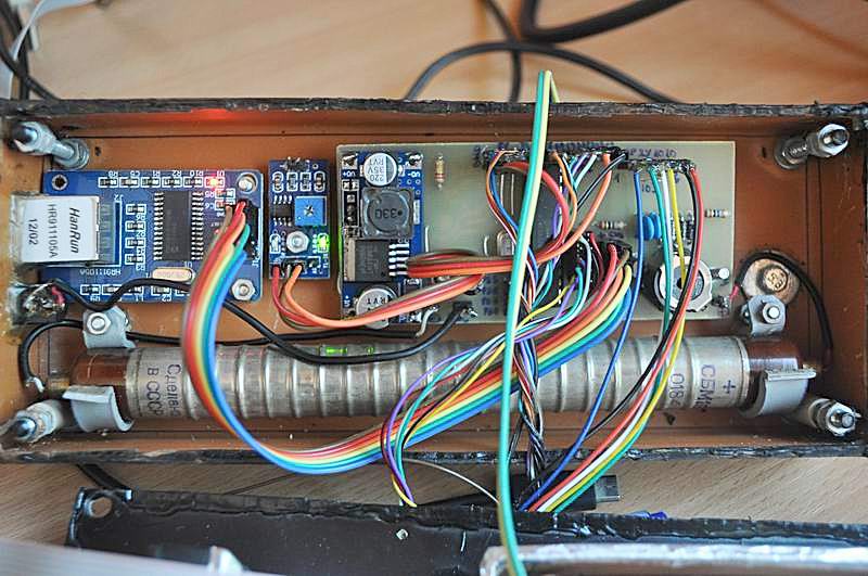
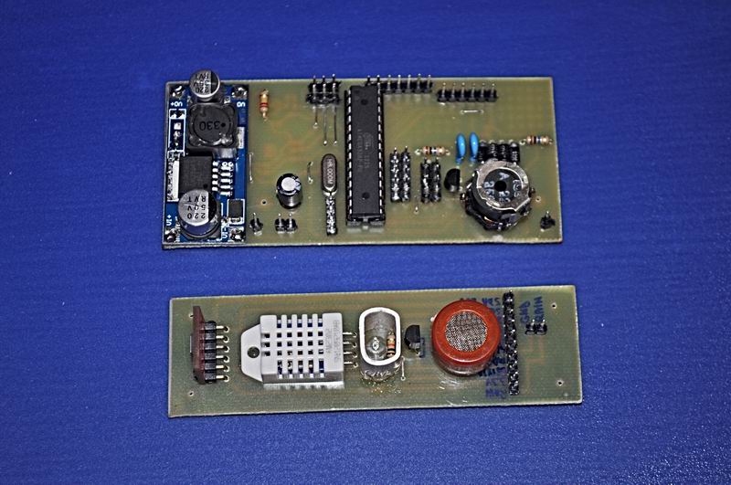
The MQ-9 is not the best approach to gas detection. It uses an filament to start micro combustion chemical reactions to detect any flammable gases . It uses a lot of current and it has a short life. And it also generates a lot of heat! Too bad I had it placed right next to the temperature sensor #1. The temperature data was completely compromised because of the “hot” neighbor. So the only solution was to move the MQ-9B outside of the sensors box. Regarding the high power consumption, it was a fortunate choice that I used the LM2596 convertor for supplying 5V, instead of using a L7805 linear converter like in the previous version. At least this one can handle all the consumers, including the gas sensor.
Finally, here is the assembly, with the new black paint layer:
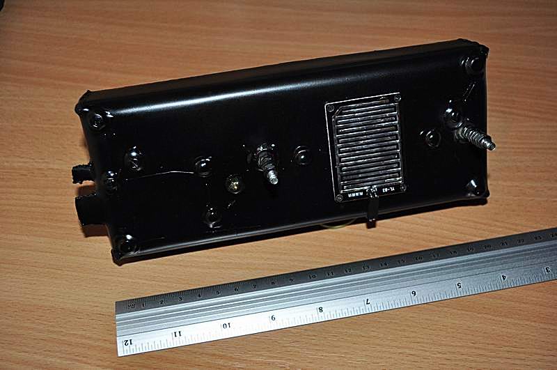

The first two pictures show the rain sensor plate, where rain droplets falling on the electrode board will generate a reading. Because I ran out of ADC ports, this information will be available as binary data only: true=it is raining or false=it is not raining, and no information on the quantity of water deposited on the board, will be collected.
The software now uploads all this additional data, and new charts have been constructed, that can be viewed here.
The voltage on the Geiger tube has been set to 380V.
December 01, 2013 – Fixing a few issues
There were some issues with this station, bothering me for quite a while now. You might have notices that the uRADMonitor went offline for the last two days. It was malfunctioning: I was hoping that the new PCB in the last upgrade would bring perfect stability, but unfortunately something bad was still happening from time to time, resulting in abnormal radiation readings. Most likely, some kind of parasitic signal was interfering with the microcontroller’s interrupt pin reading the geiger tube pulses.
So finally, I found the problem, and fixed it!
Among other changes, the project log includes:
– new mac address
– new dev id set: 00000001
– url code built using sprintf and removed websrv_help_functions so now the code is smaller, from 21K + 743bytes to 20.6K + 761bytes
– unsigned long for CPM (no more negative values because of integer sign bit being overwritten)
– added capacitor 12pF in parallel on the 220K resistor and fixed the oscillations pushing high CPM values – this most likely was the cause for the past abnormal readings
– rain sensor adjusted
– dust particle sensor checked and finalized
By having all these changes in place, the additional three sensors are now fully functional, and the Geiger tube readings should be perfectly accurate. As we had the National Day celebration today, one might say that my work for this update comes as a little gift to my fellow co-nationals and brings the station back online.
The background Radiation surveillance data is available here.
December 10, 2013 – Compensation capacitor
In the previous update I talked about adding a capacitor in parallel over the R2 capacitor: a 12pF in parallel on the 220K resistor. It helped, but from time to time I still registered abnormal readings.
Luckily, Centronic’s Geiger tube theory paper also covers this topic:
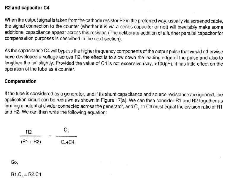
The circuit becomes:
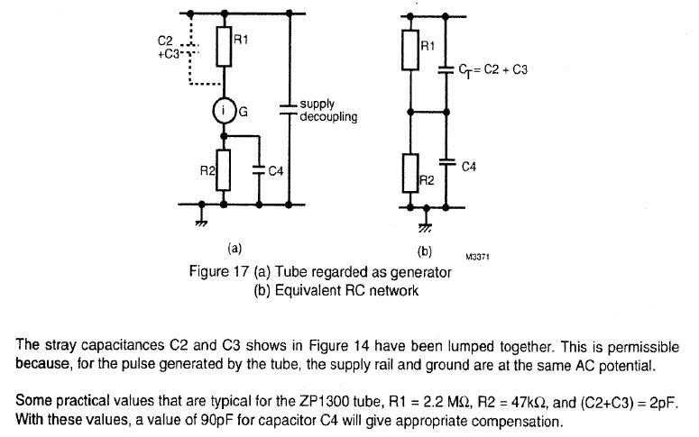
For the SBM-19 tube, the tube’s capacitance (Ct) is close to 2pF. Therefore, a suitable value for C4 is:
C4 = Ct * R1/R2 = 2pF * 10MOhm/220KOhm ~= 2pF * 45 = 90pF . I opted for 100pF (instead of previous 12pF) which solved the issues.

Pingback: Pancake Geiger Muller Counter (russian CI14B/SI14B) -1- « PocketMagic
Radu. Ajuta-ma si pe mine, te rog, cu diodele acelea BYV26E, nu le gasesc… ce pot pune in locul lor?
Multam.
Salut Alex,
Cam orice diode rapide, cu recovery-ul sub 100nS.
Sevus Radu .dar daca as vrea sa atasez un mA unde ar trebui montat?
Hi,
What is the power rating of the zenner diodes?
What voltage is the C5 capacitor?
Thanks
zenners are 0.5-1W max.
C5 can be 1Kv or higher
Hi,
I forgot to ask another questions.
What is the power rating of the resistors you use?
I see something diferent in the transformer. Primary and feedback would result in four wires to connect after winding, but i only see three in the schematic. Is it correct?
I apolagize for the silly questions. I dont know much about eletronics
Thanks
In my design, the feedback coil is created as a continuation of the primary, so in other words, last primary turn is common with first feedback turn.
I cant find the BYV26E. Do you know of any that could replace it?
Also cant find 120V zeners. Could i just use five 100v 1W zeners to reach 500 volts?
Thanks
instead of BYV26E use any fast recovery high voltage diode. Look for the recovery time, choose one under 100ns . UF4007 is a good alternative, if I remember correctly.
yes you can use 5 100V zeners
What gauges should the primary, feedback, and secondary wires be in the transformer?
I couldn’t find the 2nF 2Kv capacitors. Where can I find these? Thank you.
at a shop.
what other high voltage caps do you have? the values I gave are not critical
Like a hardware store? None so far. What should the min-max be for capacitance and voltage?
Pingback: DIY/Homemade Geiger Muller Clicker V2.0 « PocketMagic
Pingback: uRADMonitor – Online remote radiation monitoring station « PocketMagic
Pingback: Statie de monitorizare a radiatiei de fond in Timisoara « PocketMagic
It would be great and interesting to have these spread all around the world!
Pingback: uRADDosimeter – homemade digital Radiation Dosimeter « PocketMagic
Hello! can i replace the 2N5551 in the v3.2 schematics with a BC548? The 2N5551 it’s very hard to find..
Thank you!
@Juri yes. The components are not critical.
Salut, Radu.
Doresc sa construiesc si eu o statie ca a ta si sa o montez in Bucuresti. Ma poti ajuta cu proiectul iau eu achizitionez piesele? Multumesc.
Salut Alex,
Daca timpul imi permite te ajut cu placere . Ai adresa mea de mail la About.
Pingback: uRADMonitor – Online Radiation monitoring station « PocketMagic
Hi! I’m trying to create the v3.2 circuit. But I have a question (I’m using a SBM19 tube which needs a 400V supply):
If I used a string of 4 zener with a 120V threshold wouldn’t I reach the voltage of 480V instead of 400?
Should I choose 4 zener with a 100V threshold instead of 120?
@MicheleT yes, please use 4x Zener 100V , but make sure to measure the output and adjust if needed.
@Radu Motisan
Thank you, now i will try. How can I adjust if it will be wrong? changing number of wires in the trasformer?
At store they asked me about the operating voltage of piezo buzzer? What are you using?
@Alex, I’m not sure, these yellow/green piezos where from a NOS Stock and I didn’t find their specs. I’d go with what I can find
Hello Radu! I have been looking at your project for some time as I’m very keen on making one for myself.
I’ve been interested since my old DRSB-01 broke, and hoping that I could use the SBM tube from it.
However, I am having difficulty finding a way to recreate your HV power supply.
I feel that it would be easier for me to use a DC-DC Boost (around 3v to 400v) instead, but please correct me if that won’t work.
I don’t mind too much about power consumption, just whatever’s easier to make.
@Yuri, hi! My skills in electronics initially developed close to high voltage applications like inverters, this is how I became used to booster converters. My suggestion is to go and invest the time you need to get things right, you learn it once, and then use many times. Start with a simple 555 driven oscillator, set for 20-30kHz and a small ferrite core.
so awesome I cant really build it but can I buy it
Can you please specify the transformer device?
I’m finding some problems in creating 3.2v circuit. I’m using a bc547c transistor instead of bc548, because I’m not able to find it. But when I read the voltage at the output of the 3 stages multiplier I see 0V !!! So I thought that the transistor wasn’t able to turn on and oscillate. I try to eliminate the 2.2k resistor and connect directly the transformer with the emitter. Better, but only 40V . What can be wrong?
I’m wrong in the previous post. I eliminate the resistor of 2.2k and tried to connect directly the base with the transformer, resulting in only 40V.
Hi Radu, also noticed the instability problem.
Have you considered that it may be externally caused?
Last time there was a big thunderstorm one of my counters went berserk, reading hundreds of counts per minute.
Later found that the tube was very sensitive to overvoltage and reducing it to 445V (max according to datasheet) with series diodes fixed it.
Maybe a particularly large TGF set it oscillating?
A related idea is to include a scintillator+diode sensor as well, the idea is that this provides a sanity check in the event the tube goes dodgy.
If both tube AND diode register an event it gets recorded and the tube power gets cut for a few seconds to let it reset 🙂 I have some sheet from Stella if this helps.
Hi,
My congratulations !
I’ve never thought to see again someone to design and build from scratch from a to z an electronic project (a wonderful one also) !
That plastic glass ferrous-chloride etching was very touching for for me, reviving 40 years old memories… thank you.
BTW, 0,12usV is really the background radiation level for Timisoara (same on my GammaScout), very acceptable, God bless.
However, higher level in specific places (or in objects, trees, etc.) can be found over the Timis county.
Adding pictures feature for comments, would be very useful thing also.
Keep going and good luck.
Sincerely yours.
Thank you , Vio. I am trying to give something back to the community. Feel free to send me pics via my email address (you can find it under the About section). For a newer dosimeter variant, see http://www.pocketmagic.net/diy-dosimeter-geiger-counter-kit/
Meanwhile I’ll try to add picture feature to the comments as well.
Pingback: Uradmonitor - Electronic Ştefan