
Both are neat little devices, that can offer useful data to your hardware applications. The DS18B20 comes with better temperature interval and resolution and with more features, but the DHT11 is cheaper and also provides humidity data. Which one is better? It depends on your application. Below see how to use them both, with two small size libraries to keep the program memory to a minimum.


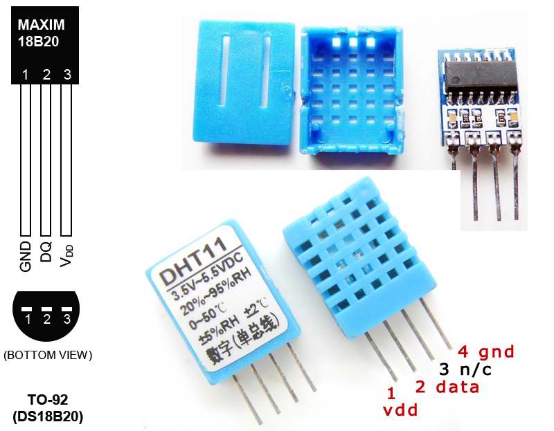
DS18B20 – digital temperature sensor
My previous article on the DS18B20, focused on getting only the positive temperature values out of this sensor’s Scratchpad. For a better approach the 12 bit data needs to be interpreted correctly, with the most significant bit as the sign bit. This leaves us with 11 bits for the integer temperature part , and 4 bits for the decimal.
A few bitwise operations, and a little bit level surgery, gets the job done.
// first 12bits represent the integer temperature
// the last 4bits represent the fractional temperature
// I I I I I I I I I I I I F F F F
//Store temperature integer digits and decimal digits
uint16_t integer_bits = temp >> 4,
		fractional_bits = temp & 0xF;
int negative = 0;
if (integer_bits & 0x800) negative = 1; //the 12th digit is one, representing a negative number
Here’s a direct conversion using the float data type:
float therm_read_temperature() {
	//Reset, skip ROM and start temperature conversion
	therm_reset();
	therm_write_byte(THERM_CMD_SKIPROM);
	therm_write_byte(THERM_CMD_CONVERTTEMP);
	//Wait until conversion is complete
	while(!therm_read_bit());
	//Reset, skip ROM and send command to read Scratchpad
	therm_reset();
	therm_write_byte(THERM_CMD_SKIPROM);
	therm_write_byte(THERM_CMD_RSCRATCHPAD);
	uint8_t l = therm_read_byte();
	uint8_t h = therm_read_byte();
	therm_reset();
	float temp = ( ( h << 8 ) + l )*0.0625;
	return temp;
}
The DS18B20 can do much more than this . See the complete datasheet, here.
DHT11 - cheap digital temperature and humidity sensor
This Temperature & Humidity Sensor features a temperature & humidity sensor complex with a calibrated digital signal output. It includes a resistive-type humidity measurement component and an NTC temperature measurement component, and connects to a high-performance 8-bit microcontroller, offering excellent quality, fast response, anti-interference ability and cost-effectiveness. Datasheet here.
This sensor returns sequences of 5bytes representing the humidity integer value, the temperature, and a checksum. To get the values correctly, precise timing at the 40uS scale is required.
// READ OUTPUT - 40 BITS => 5 BYTES or TIMEOUT
for (int i=0; i<40; i++)
{
	loopCnt = 10000;
	while(!(DHT11_PIN&(1< 40) bits[idx] |= (1 << cnt);
	if (cnt == 0)   // next byte?
	{
		cnt = 7;    // restart at MSB
		idx++;      // next byte!
	}
	else cnt--;
}

// WRITE TO RIGHT VARS
// as bits[1] and bits[3] are always zero they are omitted
*humidity    = bits[0];
*temp = bits[2];

uint8_t sum = bits[0] + bits[2];

if (bits[4] != sum) return DHTLIB_ERROR_CHECKSUM;
return DHTLIB_OK;
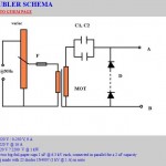
Schematics:

Source code:
I have designed the code for an Atmega8 microcontroller. The code is available here.
Pingback: ATMega8 and DS18B20 (digital temperature sensor) « PocketMagic
Pingback: Atmega8 and enc28J60 for ethernet support « PocketMagic
Hi
I m using a atmega8l 8pu Ic to drive two gear motor for line lollowing robot with four comparator input by four sensor, two from left of black line and remaining two on right side of the black line. plz provide me the program code for it on my mail id
calltoangel@yahoo.com thax in advance….
Hey,
I’m using the DS18B20 with an Atmega8515, the sensor is placed on Pin 0 of port A.
But when I try to change the port letter, it fails and gives me a lot of errors.
I’m not using port c as input, but as output to drive the LCD.
Nor i’m using port b or d.
Plz help me out,
thanks in advance!
What errors are you getting? Making this change should be trivial.
I’ve changed
//#define THERM_PORT PORTC
//#define THERM_DDR DDRC
//#define THERM_PIN PINC
//#define THERM_DQ PC5
to this:
#define THERM_PORT PORTA
#define THERM_DDR DDRA
#define THERM_PIN PINA
#define THERM_DQ PA0
in the therm header file
and in the Atmega test.c i’ve changed all PORTB to porta also,
thx for responding so fast!
I’ve send you an e-mail with the errors I get.
My e-mail address is sebbie94@gmail.com
Thank you in advance!
In AVR Studio, you need to change ATmega8 to your new target microcontroller.
I did, but then I still have one error left, and it’s not easy to find because AVR doesn’t indicate the errors after I change the configuration options.
Sent new e-mail, because I don’t want to post too much text.
That looks strange, are there any other changes you did to the code ?
No, the only thing I have changed was this.
Should I mail you the complete project (zipped)?
Mail set including whole project
You sent me my own code, from the old ds18b20 article 🙂
You need to use the code posted under this article, at the bottom:
“I have designed the code for an Atmega8 microcontroller. The code is available here.”
Good luck!
Ow, sorry. My apologies!
Thank you for helping me!
Hi.
Which frequency oscilator I should choose?
16Mhz
How I can use this frequency in internal oscilator? I have only 1,2,4 and 8MHz internal in Atmega8. Should I use the external oscilator?
Regards.
Any option is ok, but you’ll need to change the code (F_CPU) to the frequency you are using.
This is project for Atmel studio? I can’t open this as project, only code ;/
Sorry for post under post. I open this as project 😉 Where I find F_CPU? (which file)
Pingback: ATMega8 and DS18B20 (digital temperature sensor) « PocketMagic
Does this project work with DHT-22?
For DHT-22 see: http://www.pocketmagic.net/2012/11/temperature-and-humidity-sensor-dht-22/
Hi, I want to ask for this project is use what value for crystal? 16MHz?? or 8MHz? the LCD is 1602??? atmega8 IC = ATMEGA8-16PU ??Because im beginner for micro controller. Thanks.
I want to ask also if i want to do the DHT22 and DS18B20 with atmega8 using this source code is ok?? just replace the DHT11 to DHT22? Thanks.
Hi I have a problem with the dht11 sensor. I have connected all things together despite the ds18b20. The dht11 shows T:0 and H:0!! I think that probably the sensor could be damaged?? How do you think. Thanks in advance.
hi….
I have a one Question..
i’m use ATMEGA32 and 7.3728Mhz Crystal
and Port,Pin,DS18B20,SHT11… all Same..
But DS18B20 Result is “85.000”
Help me.. plz…
Hi! Excelent work!!, i have a two questions… Your ds18b20 library support negative temperatures?? And the last…. How can skip a 85 degree Celsius? when ds18b20 power-up
Thanks
Regards, sorry for my bad english
Hello Alan,
Yes, it reads negatives as well. For the invalid readings (85, etc), you’ll need to implement the CRC verification. The code is:
/* 16bits answer, temperature range -55 .. +125 *C */
int DS18B20::readTemperature(float *temp) {
//Reset, skip ROM and start temperature conversion
if (THERM_OK != reset()) return THERM_ERR;
writeByte(CMD_SKIPROM);
writeByte(CMD_CONVERTTEMP);
//Reset, skip ROM and send command to read Scratchpad
if (THERM_OK != reset()) return THERM_ERR;
writeByte(CMD_SKIPROM);
writeByte(CMD_RSCRATCHPAD);
// Read 9 bytes memory
uint8_t mem[9] = {0};
for (unsigned i = 0; i<9; i++) {
mem[i] = readByte();
}
// compute CRC and fail if CRC is not valid
if (crc8(mem, 8) != mem[8]) return THERM_ERR;
// compute temperature readings
int16_t sword = (mem[1] << 8) + mem[0]; *temp = ((float)sword) * 0.0625; // drop initial 85 powerup readings if (powerup && *temp == 85) return THERM_ERR; //if (THERM_OK != reset()) return THERM_ERR; powerup = false; return THERM_OK; }
Ok, Thanks for your reply, I try it and I tell you what happened 🙂
Regards
Hi!
i´m look the code and i have aquestions…,whats means THERM_OK and THERM_ERR? what is the data type?, is a define statement, or bool…or any other, powerup is a bool data type, right? ,
regards, and sorry, i´m a begginer