This article is directly related to electronics, high voltage and arcs. Its purpose is to describe one of the latest additons to my High Voltage collection: a ZVS Driver. A ZVS driver is a resonant zero-voltage switching driver. You can read more about it here
For my variant I’ve used the following:
– 2xIRFP460 Mosfet / 500V, 20A
– 2x270Ohm 5W resistor
– 2xBYV26E 1000V/1A fast diodes
– 2xZenner diodes
– 0.33 x2 Capacitor
– 2mm Cu wire for the 5+5 turns flyback primary
Schematic is here:

The Inductor I’ve use has very few turns, that gives a lot of current on the flyback output. For 14V / 4A input the mosfets stay cool, so a small aluminum cooler was sufficient.
Here is my circuit’s assembly:
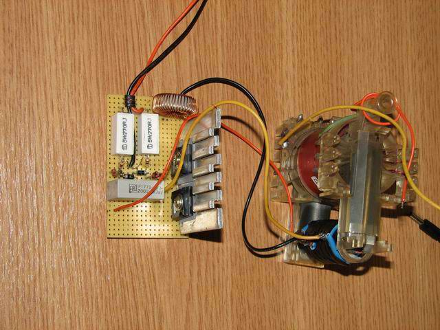
The arcs produced by this driver are very hot, the copper ground wire goes red quickly, and anything brought close to the arc is incinerated. Be careful if you’re planning to build one of these. You can see more high voltage power supplies here.
You may also use the ZVS Flyback Driver with a Ferrite core and a custom made HV secondary, see this article.
Or you can use a secondary with only a few turns of tick cooper wire, to get a current so high, that can melt thin copper wires connected across the output. This would be a High current inverter.
boss ang galing mu ah,, panu mu ginawa ang inductor? ilan AWG at ilang turns at ilan din a diameter ng inductor??
Very interesting information, good pictures and useful video!
Dude
I have ZVS flyback driver with pcb.
My zvs driver
[img]http://img121.imageshack.us/img121/4695/myzvsschem.jpg[/img]
[img]http://img204.imageshack.us/img204/4852/zvsdriver1.jpg[/img]
[img]http://img204.imageshack.us/img204/8092/zvsdriver2.jpg[/img]
[img]http://img163.imageshack.us/img163/7618/zvsdriver3.jpg[/img]
Try to use a more powerful input. 30V or more and min 4A …then you’ll get better arcs. Use two transformers out of an overhead projector, like used in schools. Connect the output (10A, 24V)in series -> 48V 10A…thats a lot of power for a ZVS driver 😀
@seppelpole: thanks for the comment. I’m planning to use a rectified variac soon.
Mr. Radu, can you explain more detail about the primary coil for the fly back ? what the mean 5+5 turns ? 5 turns plus 5 opposite direction turns OR 5 turns plus 5 same direction turns ? please help this newbie 🙂
Hi stevan, I should have mentioned this in the post.
5+5turns here means a 10turns coil with a tap in the middle.
so they are all in the same direction.
let me know if you have any other questions.
Mr. Radu, about the fast diode. is 1n4007 not fast enough to replace byv26e for fast diode ?
thanks.
@stevan, 1n4007 is not good, and yes that’s because of speed. You can use other diodes then byv26e but check their data sheet to see the Reverse Recovery Time.
salut! Am si eu o nelamurire legata de Zvs, firele din bobina L1 sunt izolate sau nu? si ink o intrebare: se intampla ceva dak nu folosesc ultima dioda HV D5?
EN: what kind of wire is used in L1? Can I renounce the HV D5?
Sau cu ce as putea inlocui dioda 5? cu ceva mai comun,ceva care sa o gasesc mai repede.Ms
ciao chupy, da firele din bobina sunt izolate, e sarma CuEm mai groasa. poti sa nu folosesti dioda HV, era pt redresarea output-ului.
EN: it’s CuEm tick wire. You may skip the HV diode, it was for half rectifying the output.
Ms mult si ink ceva , de unde ai facut rost de tor pt bobina?eu am gasit vreo doua da sunt cam mici;)) Incerc sa mi fac si eu o tesla coil am toate componentele inafara de torul ala din ferita si condensatorul de inalta tensiune . Am vazut k ai un post cu Condensator HV 18 kv. O sa incerc sa mi fac si eu unul 😀
EN: what kind of tor should I use? I would like to use the ZVS to build a tesla coil. I’m wondering if I could build a homemade HV capacitor.
torul pt bobina poate fi si mai mic, dar sa fie din pulbere de fier presata, probabil ca ce ai tu e bun. se gasesc in surse pc, in filtre sau chiar pe placile de baza. invarte vreo 20 de spire pe el si ai terminat.
te incurajez sa-ti faci singur condensatorul HV, eu la tesla coilul meu am unul homemade si merge bine (comparativ cu cei din comert, care sunt f scumpi si se ard repede)
LE: era sa uit: vezi sa incerci sa cositoresti piesele direct pe picioarele mosfetilor! sa nu faci circuite cu cablaje sau fire lungi, ca nu va functiona bine. Uite la ce ma gandesc: http://www.pocketmagic.net/wp-content/uploads/2009/01/img_1805.jpg
—-EN—-
The tor can be smaller as well, but it should be made of ferrous pressed powder, probably what you have there is ok.
I strongly encourage you to build your own HV capacitor (works good for tesla coils)
LE: try to build the ZVS directly on the mosfets like in the picture. Long wires will not work.
Nu conteaza numarul de spire de pe tor (in post am vazut ca is 40 si de asta am intrebat k torul meu e cam micut si nu imi incap 401 de spire;)) )? Am observat in filmuletul tau ca a cedat condensatorul si ma gandeam dak pot sa pun o foie de hartie intre cele doua straturi de plastic? Sau sa folosesc un plastic mai gros?
—EN—
How many turns for the tor coil?
Also regarding your homemade capacitor, I’ve seen it failed, can I use better dielectric: ticker plastic or some paper?
oh no….
Mr. Radu, can you translate that in english ?
ma scuzi k sunt cam insistent (sunt incepator si … ma lamuresc cam greu).M-am uitat pe link si nu am vazut condensatorul de 3 uf .Ala Mp250 rosu ce e? 😀 ms ink odata:)
@stevan: done, text translated.
@chupy: poti pune 20 spire. in mod normal ar trebui totul calculat, nu facut dupa ureche, dar oscilatorul asta e destul de “permisiv”. posteaza te rog intrebarile despre condensatorul in postul corespunzator, ca zapacim lumea.
pt ZVS poti folosi condensatori de 630V2.2uF cu rezultate bune. Dar pentru inceput pune ce ai. Eu am folosit la inceput condensatori de tip x2 din surse pc. Voltaj macar 250V si macar 1uF.
Am gasit vreo doi pe acasa.3.3uf 250v,4.7uf 400v,47uf 400v pe care mi l recomanzi sa l folosesc?
4.7uf 400v
Cu ce curent alimentez circuitul continuu sau alternativ?
continuu, urmand ca circuitul sa oscileze.
Am o nelamurire legata de irfp. CAre din pini vin legati intre ei si cu minusul ? cel din mijloc sau al 3-lea pin?
Chupy, http://www.datasheetcatalog.org/datasheet/stmicroelectronics/6179.pdf
in leg cu condensatorul: asta e tot ce am gasit:((celelalte erau arse): http://i883.photobucket.com/albums/ac36/loghin/DSC02327.jpg
e bun?
da.
Am probat astazi oscilatorul legat de traf ,l-am pornit pentru 2 sec , l-am alimentat cu o sursa de pc 12v si vreo 5-7 A si mi-a iesit fum de la torul ala bobinat(40spire de 0.7 🙁 ).Apoi am zis sa l alimentez cu o tensiune mai mica fara traf.(5v 3A) si i am masurat rezistenta si voltajul la iesire si am aceleasi valori pe ambele ramuri ,nus ce am gresit? legaturile is facute bine exact k in schema. Vreo sugestie?
Apoi am legat si traful la oa oscilatorul pornit cu 5 v si mi s-a incalzit si radiatorul cu irfp-urile si la fel si torul.iar la traf nica nici cea mai mica scanteie 🙁
verifica totul inca o data, eventual posteaza niste poze.
M-am uitat mai bine pe schema ta D1 si D2 au simbolul diodei zenner si acolo precizeaza ca trebuie sa folosesc byv26e.Mi se pare cam ciudat .http://i883.photobucket.com/albums/ac36/loghin/simbol-dioda.jpg
http://i883.photobucket.com/albums/ac36/loghin/simbol-dioda.jpg
Hi Mr.Radu,
I want to recoil the secondary coil of the flyback to replace the original coil.
Can you give me your recommendation ?
what diameter of wire that must I use ?
how many turn that must I do ?
regular coil or bifilar coil ? or any other technique ?
I want to build the coil myself because I don’t want the Diode D5 (in your diagram), and I don’t know how to remove it from the flyback.
thank for the advice.
Hi Stevan, see http://www.pocketmagic.net/?p=585
In sfarsti am reusit si eu sa mi fac un Zvs .Merge bine da e cam slabut pentru o Tesla :(:(.Ai cumva vreun sfat k sa i marec puterea:-“?? Si ink ceva ce se intampla sa spunem dak in loc de 4+4 spire folosesc 5+5?
Bravo Chupy. Poti pune 5+5 dar vei obtine voltaj mai mic.
Iti sugerez sa pui un condensator de capactitate mai mare 3-4uF / 600V.
hi!
i’m unable to find a IRFP460. can i use IRFP350 400v 16A or IRFP250 200v 33A?
Yes, this circuit works good with other types of mosfets.
One requirement that you need to be aware of:
Try to build the driver without long wires between the components:
You can fix the 2 mosfets on a heatsink, close together, then on their PINs to solder the rest of the components. Do it like this:
http://www.pocketmagic.net/wp-content/uploads/2009/01/img_1805.jpg
The critical part is the capacitor, it must be a quality one. Also this components can heat up considerably during use.
Dude Can u explain me how to wire or connect the L1 to the primary coil and also tell me can i use this driver for a small induction heater? and also do tell me Can i connect it to a 12v 4.5ah battery
and what is the output of the driver to the coil?? i mean the primary coil… Thanks!!
Hi Salar, to connect L1 you need to make a central TAP on the primary, like (~) 5 turns (~) 5 turns (~)
where (~) is a connector.
yes you can use it for an induction heater, but the capacitor is overheating, so you need to use several quality caps put in parallel.
Yung buck converter ginamit kong driver sa flyback transformer , then ginamitan ko ng 2n3055 , so nang mag testing ako ng homemade flyback hindi umiinit yung power mosfet ko sa halip yung 2n3055 medyo umiinit lang . mga tol kung gusto nyo mag experiment sundan nyo nalang ito, yung gauge ng primary ay #14 at yung secondary ay #36
mag ikot sa secondary ng 2500 turns .
http://www.youtube.com/watch?v=wW7TMRGCTuk
Hi Rolando, is this Filipino? Could you post in English so I can better understand your question?
Hi Radu ,yes sir i am filipino a young learner to High Voltage , your website is very interesting i found many diagrams and i choose one of them . i am experimenting a flyback in HV to get a better result rather than amps for HHo or hydrogen .thank you sir for your reply .
Hello Rolando, thanks for your message. I’m glad you find this site useful. Feel free to post any questions if you need help building your HV circuits. Cheers!
Hey!! its me Salar again thank u for telling me how to connect the L1 i built an induction heater with this ZVS and i have won the science exibition but i waz having a hard time figuring out how can i further more enhance it??? i mean it just heats the nail but i am unable to turn it red hot!!!
hi Salar, please post your circuit with all the components/values used and I will give you some hints.
Hello!! okay, here are the components i used….
1)the two MOSFETS are Q1=IRFP460LC,Q2=IRFP460 i am not sure what LC stands for..
2)D3&D4 Zenner Diodes are 15V 1W with R1&R2 10k 1/4W resistors in parallel soldered on top of the zenners
3)However D1 & D2 are BYV26C not BYV26E,well! i also use schottky diodes with the same rating as that of BYV26E
found no major improvements..
4)R3&R4 are the same 270R\5W resistors (the white ceramic block type)
5)L1 has 40 windings of 0.8 enamel wire on a toroidal inductor core, i also have ferrite bar core if tht might be better
6)C1 is 3uf bipolar non-MKP type i mean just the one in this picture
http://www.pocketmagic.net/wp-content/uploads/2009/01/img_1805.jpg
7)and i dont use a toroidal flyback core for the work coil i directly
Place the workpiece in the center tapped primary!!!
8) OH! and just one thing for the input i have 12V 10A..
i hope that is not a problem caz another guy i saw was using the same but
it turned the work piece quite red hot he used a 10nf Cap.. i dont know what was the inductors value!!
i hope this is enough for u to give me tips on how to improve my ZVS for induction heating and even melting if its possible!! :p Thanks!!!
You might need to put a L7812 regulator and give 12V to R3 and R4 and allow the full voltage to L1 directly.
This way you can put higher voltage in this circuit.
I suggest you go up to 40V.
so u mean by this way i will be able to improve my induction heater?? and i don’t know how to connect the regulator iz this how?? “http://www.google.com.pk/imgres?imgurl=http://nsr125.eu/files/l7812cv_566.jpg&imgrefurl=http://nsr125.eu/neony-vt275,15.htm&usg=__K2T8D6t70Vs2nxjHbkmg1P059G4=&h=459&w=514&sz=19&hl=en&start=150&zoom=1&tbnid=E3rpb3WVdbb7NM:&tbnh=127&tbnw=125&prev=/images%3Fq%3DL7812%26um%3D1%26hl%3Den%26sa%3DN%26biw%3D1024%26bih%3D550%26tbs%3Disch:10%2C3835&um=1&itbs=1&ei=j5bqTPOWLMnDswagkKmPCQ&iact=hc&vpx=131&vpy=192&dur=9745&hovh=182&hovw=204&tx=56&ty=78&oei=lZPqTKGnOsOxtAbC2uCvCw&esq=10&page=10&ndsp=17&ved=1t:429,r:0,s:150&biw=1024&bih=550” What is the value of R in this pic??!!! It would be great if u just did a Blog on ZVS induction heater!! i mean there are just so many kids out there like me having problem with induction heaters I’ve seen other circuits of half-wave inverter for induction heater but i found the zvs really simple!! and i really think that if u made a blog on this in which u could use a ZVS for induction heating it would be Awesome!!! Just one last thing also tell me iz it better to use the center tapped coil directly or should i use a flyback core to step down and use the work coil on the secondary??
Hello Salar,
I will try to post an article on ZVS induction heating.
Please do im in great need!!!!
Good afternoon Radu
Good info!
Wanting to know if this circuit locks onto resonance of the secondary winding.
Have you ever tried to power a HHO cell w/ this?
I would like to build one of these to try to power a HHO cell in my truck.
What would be the highest amp output possible w/ this circuit?
Could it be modified to give more power?
Thanks in advance
Lost_bro
Can any type of TV flyback be used?
The frequency is determined by the Capacitor C and the primary inductance L. The secondary winding + load will vary the inductance of the primary, changing the resonant frequency as well.
I didn’t try it on HHO, but if you tell me more about that I might run a test.
For the Amp output you can get high values, see: http://www.pocketmagic.net/?p=1539
Yes, you can use any type of flyback, but remove the plastic gaps in the ferrite core since you’re driving this in Forward mode, not flyback mode.
good evening Radu
Have you heard of Stanley Meyers? He patented a system to split H2O using resonant frequency and ultrahigh voltage. He spoke of 20kv and various frequencies, but the key was to achieve resonance in the system which consisted,in part of a WFC water fuel cell, just google it, there are millions of references on the web.
You will find there are MANY different designs of HHO cells. Some use brute force, and the Stanley Meyers type use Resonance and High voltage.
He also used a ‘VIC’ a Voltage Intensifier Circuit. Maybe a modified Flyback, like you show here could be adapted to achieve the same result.
I am currently experimenting w/ Bedini systems to split h2O w/ some success, but I believe a higher current level is needed.
Email me, and I’ll send you some more info.
Take care
Lost_bro
Every time I hear people talking about resonance, I imagine a very complex process not fully understood. I’m not that into electrolysis, but I’m sure it is very hard to improve the efficiency of a process.
If you use electric power to split water in H2 and O2, burning the mixture will give you less power, so why bother?
Electrolysis works best with large surface electrodes and high currents, it doesn’t make sense to increase the voltage, for several reasons:
1. any inverter/ converter has loses
2. the high voltage obtained will have an extremely low current, not good for doing electrolysis
Hope this helps
Dear Mr. Radu,
Can you tell me how much voltage of primary coil in flyback ?
Thank you,
Stevan
In the video posted above, I’m using a pack of batteries: 12V 10Ah .
can i use a lower value cap with this inductor??
yes
umm!! would it be good to use IN5398 caz i dont have byv26e’s
you can use another diode, but check the datasheet to make sure it is an ultrafast one. (recovery times <100nS).
dude in this data sheet it says reverse recovery time is 2uS
That’s a lazy diode 🙂
It’s not good, try finding an ultrafast diode.
hahaha…. umm yea dude i found these BYM26C !!!!”30ns”!!!! & BYM26E !!!!”75ns”!!!! can i use these or should i use the ones with the same recovery times…???
umm and just one more thing iz it possible to get a frequency of 50 or 60 Hz with this inverter?? if yes then how!!!
Hey there Radu, Umm i build this ZVS driver once before and it worked well but now i have made this once again but its not working that well probably not working at all,iz it because the last time i used a 12v 4.5Ah battery but now i am using a fullwave rctified, smoothed ,non rgulated 12v 10A source… Help please!!! iv checked all th mosfets are also fin no component iz bad….
Hi Salar, please post some pictures so I can see your setup. I’ll do my best to help.
You need thicker wires for primary, I use thick automotive wire (and even those get warm). Use at least 24v input @ 5A at least (I use 24 volts @ 17amps – from two PC ATX PSUs in series). If you do this, you will draw fat white hot 4 inch arcs at least! Note: I use a long wood stick with magnet wire + thick copper end to manipulate the ground of the flyback HV output.
@RichardK, I have a DIY regulated supply with a toroidal transformer. It puts out 24V @10Amps max, rectified and filtered I get 30V. See it here:
http://www.pocketmagic.net/?p=1162
hey there mr Radu!!! here are the components i use for my ZVS for induction heating…..
i use the same ratings as in this blog but the last time it worked,when i was using lazy diodes (the black ones in the pic below IN5398 reverse recovery time=2uS ).. now it doesn’t when i am using “BYV26C 1A 600V and the other is BYM26C 2A 600V”… they both have the same reverse recovery times i,e 35ns…. the two MOSFET’s are the ‘IRFP460’,the capacitor is 3uf 250V, the inductor has 40 turns of 0.8 CuEm wire, the Resistors are the same 10k’s the small ones and 270R 5W white big ones, zenner diods are 15V 1W. i dont know what is wrong the MOSFET’s are fine i’ve checked i tried this setup with a battery no improvements … Mr.Radu please help..Note: for the supply i use 12v @10A smoothed not regulated, i also tried a battery 24V@ 5A but it did not work….
“http://www.freeimagehosting.net/uploads/38810335a8.jpg”
“http://www.freeimagehosting.net/uploads/7500055f2c.jpg”…. zoom into the red note on this one!!! Help!! MR.Radu… Thanks in advance..
hello!!
hi Mr. Radu, may I know is it possible to generate a cold plasma by using flyback driver?? cold means around 40-100 degree celsius, thank you
If the intensity of the current flowing through your discharge tube is small, you can get that temperature.
wow, its good to hear that!!! thanks…Mr. Radu, can you please show me the way to do it?? Can I get that temperature just by provide a lower input to the flyback driver but using the common flyback driver circuit design?
One thing you should do is NOT use the ZVS driver. Instead try the 555 driver presented here: http://www.pocketmagic.net/?p=802
Salar, finally here is what you’ve asked: a zvs induction heater: http://www.pocketmagic.net/?p=1731
Hi there, thanks for the article Radu !
I just had a small question about the inductor. 40 windings 0.8 cuem. There are some SELFs out there but i don t fin that 0.8 wire.. .
I found a SELF like :
Rohs yes, wire diam. 0.71 mm, ext diam 31mm, inductance 10.3mh, intensity 6a, tension 250v ac.
Is that any good ?
hi Sebo, your inductor should be fine, it is not a critical component .
Also see: http://www.pocketmagic.net/?p=1731
Thancks for the quick reply ! Interesting video.
Last weekend i found a ferrite core in a old tv on the pavement.
Now i’m studying your articles to get my zvs running. 😉
Keep up the good work.
thank you. I’ve good a few articles here, that might help you with that, have a quick search.
Hello, I have two question: On your flyback transformer, you say to use 4+4 windings on the primary, but isn’t the amount of the turns in the primary dependant on the dimension and type of ferrite material?
I am also interested in the type of D5 diode used. Like what voltage its for(Vrrm), is it dependant on whats the output voltage from flyback?
Thank you.
postback
D5 is the TV Flyback built in diode.
The number of turns in primary can be varied, but don’t go below 4+4, or you might overheat and burn your transistors.
OK, I built it. As I understand this thing act as a power supply and thus connected directly to 230V/120V? Whats(and how to determine) the frequency of this driver?
Thanks again!
Sorry, I missed the ‘important’ note: “The powersource must be able to provide several amps.” under the schematic. So I guessed this circuit still need a power source. Does the power source need to be sinusoidal(directly from a transformer), square wave or direct current?
Thank you.
Hello, I checked several schematics and in all of them… Something i don’t understand/miss here. If this is powered by a 12-36V lead-acid batteries, such as is the case in for instance this homepage: http://www.teravolt.org/zvs.php , then I don’t understand whats the use of 250V capacitators and 500V transistors(MOSFET) then…
bdstone, this is an invertor, running on 12-50V DC.
Do not plug it to 230/120!
Yeah, I already plug it in. Its cool. Too high ampage, so that my primary wiring melted, lol.. I will check with oscilloscope when I have time..
So this circuit convert DC to 230V high-frequency signal? You determine what valtage you will have with the what voltage the cap is?? Sorry, I still did not check how the circuit works, I just put straight and build it, but as I say I will check with oscilloscope when I have some time..
I am still looking for some flybacks. I can get TV screens free, but I don’t want to get whole TV scren just to get the flyback out of it.. They don’t sell this stuff in my country, or there isn’t really any interest.. I don’t have any credit card, so the eBay is out of options.. If you have some TV flybacks, or know some other options.
Ohm, I did get the flyback, and already wire it, but its from plasma globe, and the ferrite core, looks a bit smaller than the ferrite core in TV flybacks(or so it looks).
Thanks.
Hello I will need some advice on this things:
One problem which I got is that the capacitor gets really hot. Its the damn hottest component in that and I was lucky because shut it down, right before this things blow apart(it bulges severly). Only which gets this hot is 2 resistors(and I am using 10W resistors here), and one a bit more than the other(!). The other components like 2 IRFP don’t even heat up.(???!)
I am also having problem with the transformer, the primary wiring gets really really hot, while the secondary wire don’t even heat up, but what I am confused about here is that I am using it for the induction, so the primary have more turns than the secondary..
You will need a better quality capacitor, that can handle more current. Also you will need a higher rated capacitor, in terms of voltage supported.
It is normal for the primary to get hot, if this is a problem, use a thicker wire.
Is there a way to protect two MOSFETs used? I blow up whole bunch of them and I don’t want to do it anymore..
If you do this correctly, the mosfets will not blow anymore.
I think they blow up, because my secondary wire was not coiled in the same direction as the primary. Can that be a problem?
Thanks again for helping me.
I think they “blow up”, because my secondary wire was not coiled in the same direction as the primary. Can that be a problem?
Thanks again for helping me.
HI I’ve built this driver and it works amazingly well. I would like to know how much voltage out is giving me and it’s frequency too on a 12v battery?
Any clue?
Thanks
Hi there ! I’m finally in the last stages of my buildup.. . Got my homemade flyback, got most of the components lined up.. . Just a little glitch left. My condensator actually is a DC condo, i didn t see it on the site, is it okay also or does the condo have to be AC ?
Second little question, the power, i was planning to put nimh batterie packs in parallel because of the ease to recharge and the weight of lead batteries. Is it okay ? What should i aim for, 12v 8ah, or could 7.5v 6,6ah be enough ? Could i need a fuse to protect my packs ?
Thanks a lot.
http://imageshack.us/photo/my-images/99/img0056anq.jpg/
Thancks a lot, for the site, the comments, that s so much fun.. . 😀
Last thought.. . I found out the hard way that transistor quality really matters.. . Two are burned, two are no good and another pair works fine ! I m working this with 4 nimhs battery packs in series and parallel (16v,6.6a), it works fine though the arks are not too big but nice bright colors and really really hot ! ^^
I still wonder what the hv diode is, and if i can protect my battery packs.. .
But thanks anyway !
http://imageshack.us/photo/my-images/641/img0077aj.jpg/
A little motivational pic.. . 😀 That s with all the above components.. .
Looks like you’re having fun, Sebo.
Very much ! As it took me a long time to get it to work.. .
But good advice and patience gets you there ! 😉
ZVS Flyback Driver – Simulation: http://play.kendincos.com/195389/Wrvhlrvhlhldhrv-zvs-flyback-driver-simulation.html
Can you do a test to see if this will penetrate 1/2 sheet rock and kill a mouse ? Put a piece of hot dog same length as mouse and see if it reaches it with a cap that is under both ends of the hot dog.
@James, you’re joking, right?
Hi Radu I’ve build this driver and works well. What capacitor should I use to make it’s frequency to 50hz?
Thanks
Andrew
This is a high frequency oscillator.
Hi sir Radu any updates about your zvs? 🙂