
Intro
I’m a big fan of image processing that I’ve put to use in various previous projects, related to robotics and artificial vision, such as this one, or for video surveillance and motion detection, but also other work projects.
Image processing is a vast and captivating domain, handling ways of image representation and the transformations that can be applied , for unlimited applications. We can use it to extract characteristics related to the image: shapes (such as detecting human faces), numbers and text (for OCR purposes), enhancing the visibility, content readability or simply for aesthetic purposes (in photography), we can encode information (cryptography/security), or make a robot follow the user’s red jacket. The imagination is the limit.
All the image related operations can consume a lot of processing power, so optimized algorithms taking advantage of the way the image is encoded, and doing low level operations at bit level, must be used. Math is also required as many image transformations use mathematical models that not only need to work correctly, but must be implemented in the most optimum way.
Leptonica
Over the time, mostly for academic purposes I’ve implemented various libraries to handle image processing both for mobile and desktop platforms. But recently I decided to use an open source library, named Leptonica, and presented as an “a pedagogically-oriented open source site containing software that is broadly useful for image processing and image analysis applications.” A few days after using it I couldn’t go without it. Not only it offers a robust interface to the basics: various file formats, loading and saving images, supporting and converting from multiple representation systems, but it implements powerful primitives to allow almost any possible transformation on an image. It is open source and so it exposes the internal secrets to anyone willing ot customize the code or to push the performance even further. And talking about performance , it is doing great: bit-wise operations, mathematically improved algorithms, to minimize the work load and do the job in the shortest time.
A sample
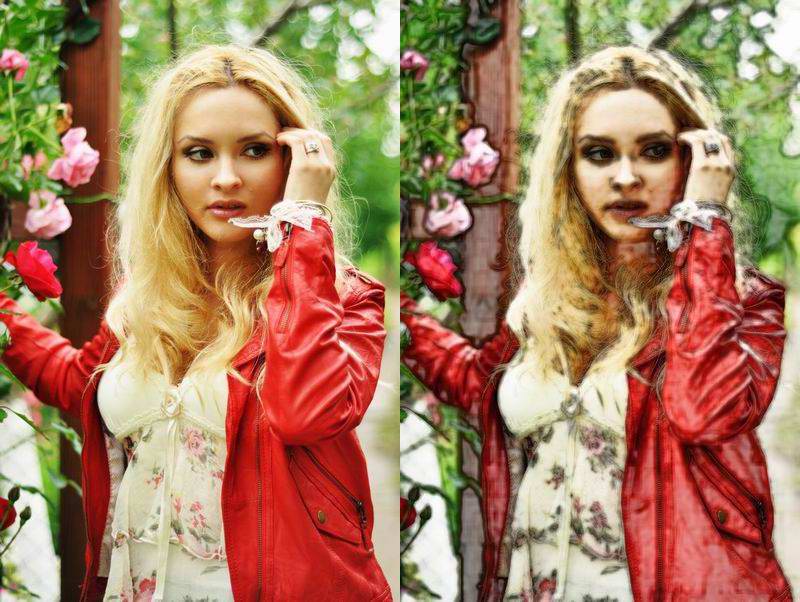
As per the article’s title, the plan is to implement a simple cartoon transformation effect, using leptonica, on a regular picture. Well not quite regular, as I chose a beautiful lady for the viewer’s delight.
 Step 1 |
 Step 2 |
 Step 3 |
 Step 4 |
 Step 5 |  Step 6 |
Step 1: loading the original image
PIX *pixSrcImg = pixRead("girl_with_roses.jpg");
Step 2: convert to grayscale, taking the maximum deviation into account
PIX *pixGrayMM = pixConvertRGBToGrayMinMax(pixSrcImg, L_CHOOSE_MAX);
pixWrite("leptonica_cartoonizer_01_gray.jpg", pixGrayMM, IFF_JFIF_JPEG);
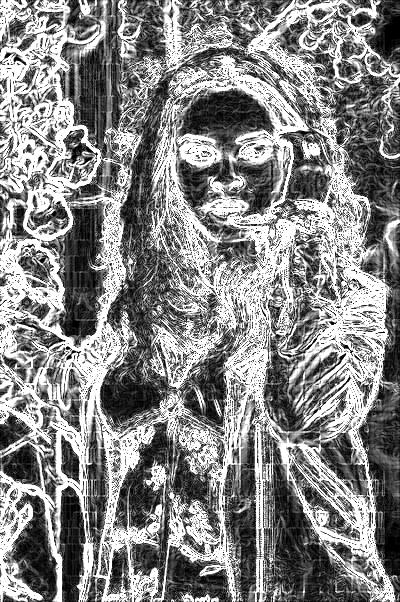
Step 3: perform edge detect
PIX *pixEdges = pixEdgeFilter(pixGrayMM,  L_ALL_EDGES);
pixWrite("leptonica_cartoonizer_02_edges.jpg", pixEdges, IFF_JFIF_JPEG);
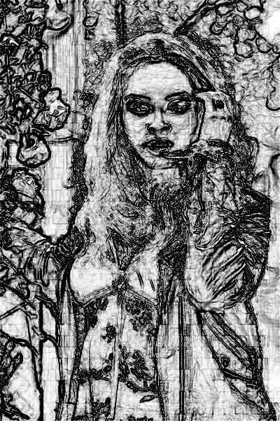
Step 4: invert the edges
PIX *pixEdgesInverted = pixInvert(NULL, pixEdges);
pixWrite("leptonica_cartoonizer_03_edges_inverted.jpg", pixEdgesInverted, IFF_JFIF_JPEG);
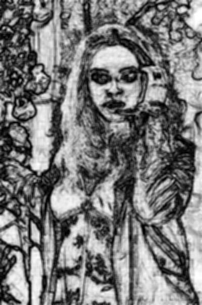
Step 5: blur the inverted edges, to reduce the roughness a little bit
PIX *pixBlur = pixBlur5(pixEdgesInverted);
pixWrite("leptonica_cartoonizer_04_blur.jpg", pixBlur, IFF_JFIF_JPEG);
Step 6: combine the last result with the original image, using a factor (150, can be changed)
PIX *pixCartoon = pixBlendHardLight(NULL,  pixSrcImg, pixBlur,0,0 ,150);
pixWrite("leptonica_cartoonizer_05_cartoon.jpg", pixCartoon, IFF_JFIF_JPEG);
Here’s the result:

The Edge-detect algorithm can be implemented as following:
/*int matrix_h[9] = {1,0,-1,2,0,-2,1,0,-1}, //sobel
	matrix_v[9] = {1,2,1,0,0,0,-1,-2,-1};*
int matrix_h[9] = {-1,-1,-1,2,2,2,-1,-1,-1},
	matrix_v[9] = {-1,2,-1,-1,2,-1,-1,2,-1}; //canny
	*/
int matrix_h[9] = {1,0,-1,60,0,-60,1,0,-1},
	matrix_v[9] = {1,60,1,0,0,0,-1,-60,-1};


PIX * pixEdgeFilter(PIX     *pixs,l_int32  orientflag)
{
l_int32    w, h, d, i, j, wplt, wpld, gx, gy, vald;
l_int32    val1, val2, val3, val4, val5, val6, val7, val8, val9;
l_uint32  *datat, *linet, *datad, *lined;
PIX       *pixt, *pixd;

    PROCNAME("pixSobelEdgeFilter");

    if (!pixs)
        return (PIX *)ERROR_PTR("pixs not defined", procName, NULL);
    pixGetDimensions(pixs, &w, &h, &d);
    if (d != 8)
        return (PIX *)ERROR_PTR("pixs not 8 bpp", procName, NULL);
    if (orientflag != L_HORIZONTAL_EDGES && orientflag != L_VERTICAL_EDGES &&
        orientflag != L_ALL_EDGES)
        return (PIX *)ERROR_PTR("invalid orientflag", procName, NULL);

        /* Add 1 pixel (mirrored) to each side of the image. */
    if ((pixt = pixAddMirroredBorder(pixs, 1, 1, 1, 1)) == NULL)
        return (PIX *)ERROR_PTR("pixt not made", procName, NULL);

        /* Compute filter output at each location. */
    pixd = pixCreateTemplate(pixs);
    datat = pixGetData(pixt);
    wplt = pixGetWpl(pixt);
    datad = pixGetData(pixd);
    wpld = pixGetWpl(pixd);
    for (i = 0; i < h; i++) {
        linet = datat + i * wplt;
        lined = datad + i * wpld;
        for (j = 0; j < w; j++) {
            if (j == 0) {  /* start a new row */
                val1 = GET_DATA_BYTE(linet, j);
                val2 = GET_DATA_BYTE(linet + wplt, j);
                val3 = GET_DATA_BYTE(linet + 2 * wplt, j);
                val4 = GET_DATA_BYTE(linet, j + 1);
                val5 = GET_DATA_BYTE(linet + wplt, j + 1);
                val6 = GET_DATA_BYTE(linet + 2 * wplt, j + 1);
                val7 = GET_DATA_BYTE(linet, j + 2);
                val8 = GET_DATA_BYTE(linet + wplt, j + 2);
                val9 = GET_DATA_BYTE(linet + 2 * wplt, j + 2);
            } else {  /* shift right by 1 pixel; update incrementally */
                val1 = val4;
                val2 = val5;
                val3 = val6;
                val4 = val7;
                val5 = val8;
                val6 = val9;
                val7 = GET_DATA_BYTE(linet, j + 2);
                val8 = GET_DATA_BYTE(linet + wplt, j + 2);
                val9 = GET_DATA_BYTE(linet + 2 * wplt, j + 2);
            }
            if (orientflag == L_HORIZONTAL_EDGES)
                vald = L_ABS(	matrix_h[0]*val1 + matrix_h[1]*val2 + matrix_h[2]*val3 +
								matrix_h[3]*val4 + matrix_h[4]*val5 + matrix_h[5]*val6 +
								matrix_h[6]*val7 + matrix_h[7]*val8 + matrix_h[8]*val9) >> 3;
            else if (orientflag == L_VERTICAL_EDGES)
                vald = L_ABS(	matrix_v[0]*val1 + matrix_v[1]*val2 + matrix_v[2]*val3 +
								matrix_v[3]*val4 + matrix_v[4]*val5 + matrix_v[5]*val6 +
								matrix_v[6]*val7 + matrix_v[7]*val8 + matrix_v[8]*val9) >> 3;
            else {  /* L_ALL_EDGES */
                gx = L_ABS(	matrix_v[0]*val1 + matrix_v[1]*val2 + matrix_v[2]*val3 +
								matrix_v[3]*val4 + matrix_v[4]*val5 + matrix_v[5]*val6 +
								matrix_v[6]*val7 + matrix_v[7]*val8 + matrix_v[8]*val9) >> 3;

				gy = L_ABS(	matrix_h[0]*val1 + matrix_h[1]*val2 + matrix_h[2]*val3 +
								matrix_h[3]*val4 + matrix_h[4]*val5 + matrix_h[5]*val6 +
								matrix_h[6]*val7 + matrix_h[7]*val8 + matrix_h[8]*val9) >> 3;
				vald = L_MIN(255, gx + gy);
            }
            SET_DATA_BYTE(lined, j, vald);
        }
    }

    pixDestroy(&pixt);
    return pixd;
}

Thanks for excelent post.
I’ve implemented this approach but the final result is not good.
May I know which edge detection algorithm you are using please? I’m using Sobel:
PIX *edges = pixSobelEdgeFilter(gray, L_ALL_EDGES);
and there are less edges compared to step 3 image.
Also, I’ve used this kernel for bluring the inverted edge image:
static const char* BLUR_KERNEL = ” 5 10 20 10 5 ” ” 10 20 50 20 10 ” ” 10 70 140 70 10 ” ” 10 20 50 20 10 ” ” 5 10 20 10 5 “;
L_KERNEL* bKernel = kernelCreateFromString(5,5,2,2,BLUR_KERNEL);
PIX* blur = pixConvolve(inverted, bKernel, 8, 1);
Thanks
Hello Mamad,
Can you post a few pictures to show me what results you are getting?
@Mamad, I got your email and pictures, and added the Edge Detection filter code at the bottom of the article. Good luck with your project, don’t forget to post it here when its done – I’d love to see it!
Hi Radu,
It is working very well now. I need to investigate more to see how can I automatically adjust brightness (and contrast) of the input image to get the best results. I will update you when its done.
Thanks again for your great post.