
Using LCDs in my microcontroller projects is nothing new for me. Back in 2009 I was putting together my very first code library to display content on a 2×16 LCD hooked up to a ATMega8. The original article is still available here.
For the Android Controlled robot project, I’ve decided I’ll be needing an LCD, to show various parameters and make debugging easier. In the end it will also be useful to show content to the user on various topics, like low battery, or GPS coordinates.
So, here is an improved version of the HD44780 LCD library code.
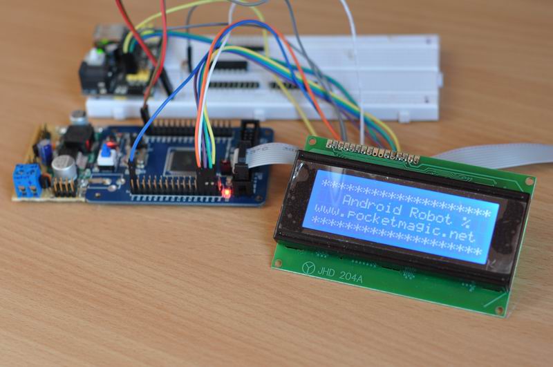
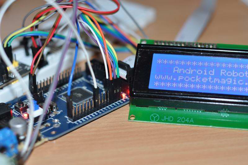
1. Classic 4Bit HD44780 code: using 6 wires to connect the LCD
To save a few pins, I’ve connected the LCD in 4 bit mode. We are only using D4,D5,D6 and D7. Also RS and E. So 6 pins are used on the microcontroller. The Atmega128 has plenty IO pins, still if you need to optimize, see the next paragraph, where I used a 74HC164 to serialize the LCD data and use only 3 pins.
To use the LCD you need to include the HD44780 library. Then call the init function:
	HD44780 lcd;
	// init LCD: RS, E, D4, D5, D6, D7
	lcd.lcd_init(&PORTA,PA6, &PORTA,PA7,
		&PORTA, PA5, &PORTA, PA4, &PORTA, PA3,&PORTA, PA2);
As you can see, you need to provide all LCD pins in the function call. This is a very easy way to go, and even allows you to create multiple LCD objects if you want to use more than one display at the same time.
The connections are as follows: RS – PA6, E – PA7, D4 – PA5, D5 – PA4, D6 – PA3, D7 – PA2, but you can change this to any other configuration.
Source code: atmega128_parallel_HD44780_LCD
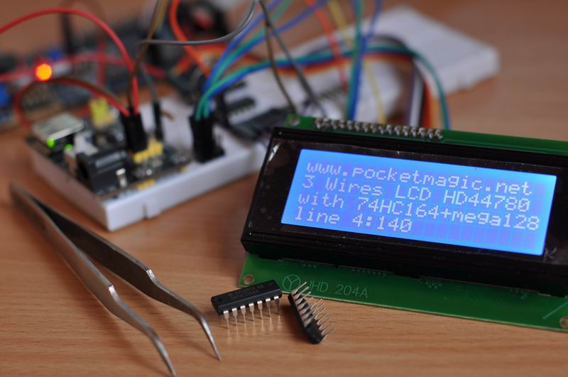
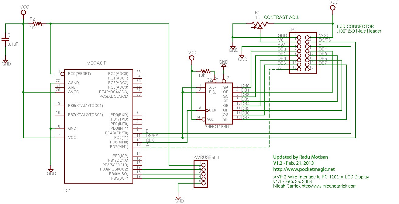
2. Shift register 74HC164: using only 3 wires to connect to the HD44780 in 8bit mode
Running the LCD in 8 bit mode, means that we will use all the D0,D1,..D7, RS and E pins. That’s a total of 10 wires/pins, and would mean a complete waste of IO pins on a regular microcontroller.
Using a shift register instead, we can cross the boundaries between the parallel and serial worlds. By doing so, it is easy to reduce wire counts, pin use and even help take load off of the cpu by being able to store their data.
For this example, I will used the 74HC164, a 8 bit, serial in parallel out, non latched, shift register.
To better understand this last sentence, here are a few additional details (source).
First, the name:
74 — places it as part of the 74xx logic family, and since its logic it cannot directly control very much current (16-20ma for the entire chip is common), for more current transistors can be used.
HC means its a high speed cmos device and a low power device that will run from 2 to 5 volts.
164 is the model number for this chip, more info is available here.
“8 bit”
A shift register is made up of flip flop circuits, a flip flop is 1 bit of memory, this one has 8 (or 1 byte of memory). Since it is memory, if you do not need to update the register you can just stop “talking” to it and it will remain in whatever state you left it, until you “talk” to it again or reset power.
“serial in parallel out”
This means the shift register takes serial data (received from a microcontroller, our atmega128 in this case) and places each bit on the correct output pin. This data processing model only requires 2 wires for total control (one for data, and one for clocking), so you can use 2 digital pins on the microcontroller, and break those 2 out to 8 more digital, parallel outputs.
This fits our purpose perfectly. We want to send the LCD data in a serial mode, using only a few wires, feed it to the 74HC164 that will provide the many parallel connections required by the HD44780.
“non latched”
As data enters a shift register via serial, it shows up on the first output pin, when a clock pulse enters in, the first bit shifts over 1 place, creating a scrolling effect on the outputs, for example 00000001 would show up on the outputs as 1, 01, 001, 0001, 00001, 000001, 0000001, 00000001 .
If your talking to other logic devices who are sharing the same clock and not expecting this, it could cause issues. Latched shift registers have an extra set of memory, so once the data is done entering the register you can flip a switch and show the outputs, but it adds another wire, software, and things to keep up with.
As explained above, it is possible to connect to the HD44780 using only 2 wires, but this complicates the code. To keep everything crystal clear, I opted for a 3 wire interface. One wire for the data, one for the LCD’s E pin, and another one for the Clock. The wiring can be see below. 74HC164 Pin 14 is Vcc and is connected to 5V, Pin 7 to GND, and Pin 9 via a 10K pull up resistor to VCC.
Similar to the first paragraph, the code encapsulates the HD44780 functionality in a class, where the init function takes the ports and pins used to connect the device. This way you can hook up multiple LCD’s to your microcontroller, if required by your application.

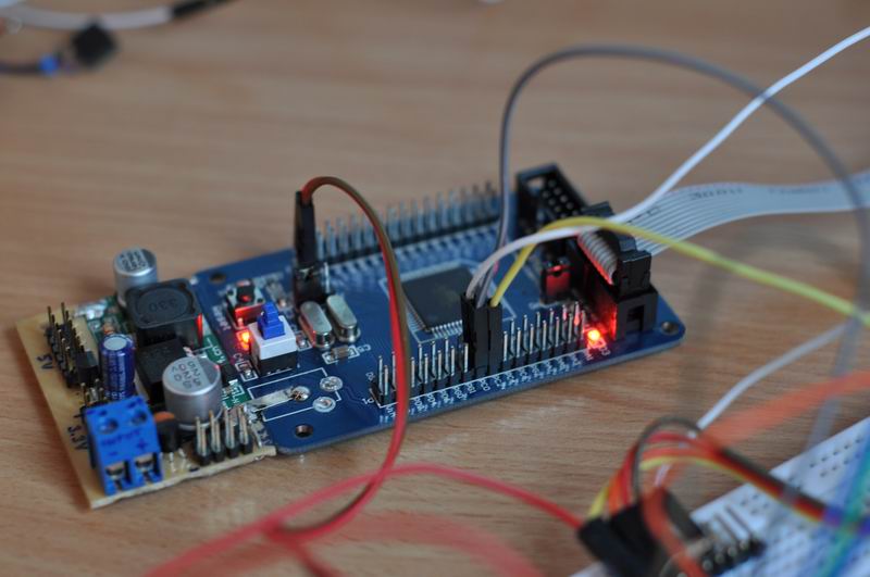
The last photo shows the three wires (gray, white, yellow) used to control the LCD. Now this sure saves a few pins, considering the LCD is connected in 8 bit mode!
The code is configured to use the following pins: RS/DATA – PA0, CLK – PA1, LCD E – PA2, but you can change it as you like.
Download the 3 Wires, 74HC164 code: atmega128_3Wire_74HC164_HD44780_LCD
A big thank you goes to the following articles:
The 74HC164 Shift Register and your Arduino using GD74HC164 microcontroller
AVR 3-Wire HD44780 LCD Interface (avr-gcc)
arduinoshiftreglcd

Pingback: ATmega8 and 2×16 HD44780 LCD « PocketMagic
Pingback: NMEA GPS Library for AVR Microcontrollers « PocketMagic
Pingback: Android controlled robot – Part 2 « PocketMagic
Pingback: Using FS1000A/XY-FST RF Radio module with AVRs « PocketMagic
I have a 1 line x 16 characters I’m trying to use on a Atmega8.
I’ve changed the pins to the ones used in Atmega8:
lcd.lcd_init(&PORTD,PD3, &PORTD,PD4, &PORTB, PB0, &PORTD, PD5, &PORTD, PD6,&PORTD, PD7);
and set in hd44780.h:
static const int LCD_LINES = 1; // number of visible lines of the display
static const int LCD_DISP_LENGTH = 16; // visible characters per line of the display
and in timeout.h:
#define F_CPU 8000000UL
Unfortunately I only get gibberish on the display:( Any ideas?
Pingback: Digital bench power supply - PocketMagic