Featured on Hack A Day, check it out here!
My friend Kevin, contacted me for building an advanced autonomous companion robot. The final goal is to make the robot follow you. This is the construction log page, with more content added as the project moves on. As this project continues what I have shown in a previous article, you can see this post a a follow-up, named as Part2.
1. January 21, 2013
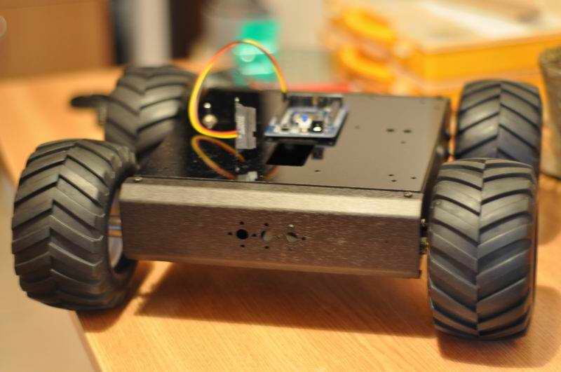
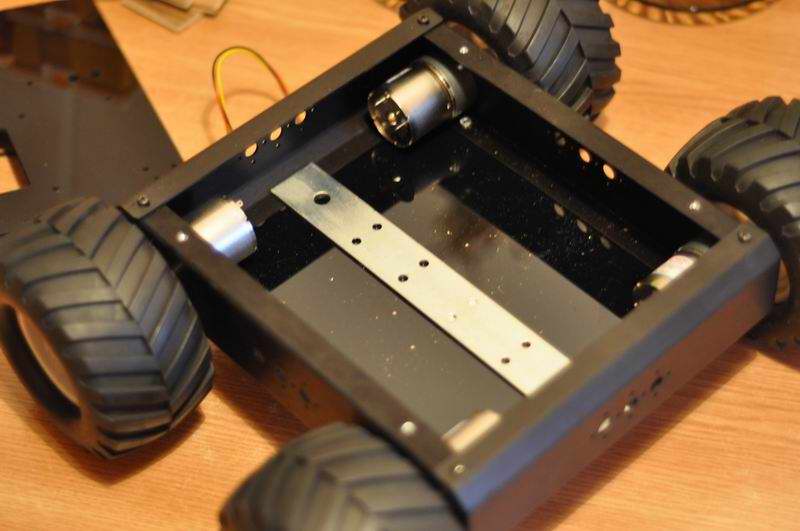
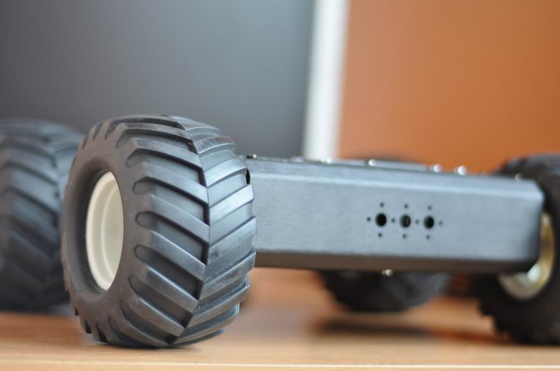
Kevin carefully prepared everything for the long trip, and the package with the hardware components got here today. For the new robot I will drop my previous Ara robotic rover platform, in favor of the neat A4WD1 from Lynxmotion. Essentially this is a similar differential control rover platform, using 4 geared motors of 200RPM 37mm diameter, one for each wheel (HN-GH12-2217).
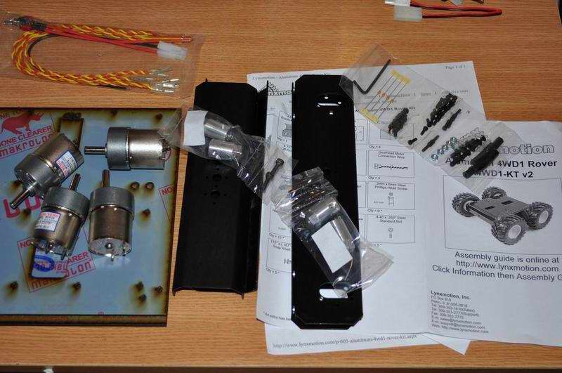
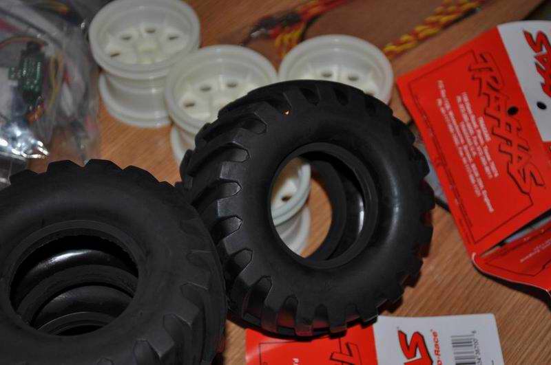

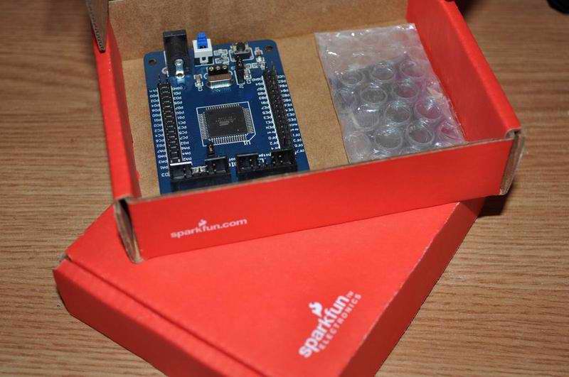
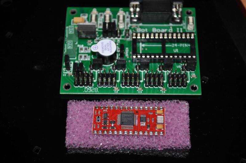
Putting the rover together was easy except for the tires which required a little Vaseline. The robot’s central processing unit will be an Atmega128 microcontroller and not the Lynxmotion’s BASIC Atom Pro 28 Pin (which also requires the custom “bot board II“). Atmega128 wins here with its 128KB flash memory, 16MHz max operating frequency and a multitude of IO ports, while the Basic atom pro can only provide 32K of Program Space and a limited operating frequency (Not to mention the costs, Lynxmotion products are also very expensive).
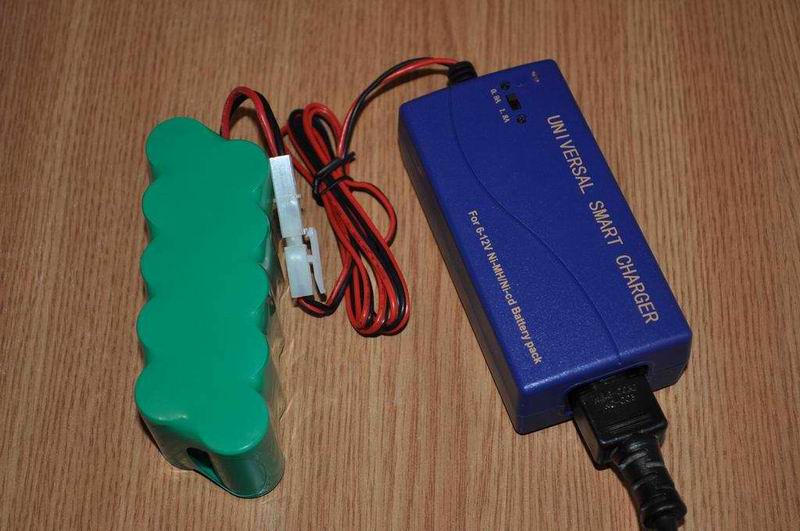
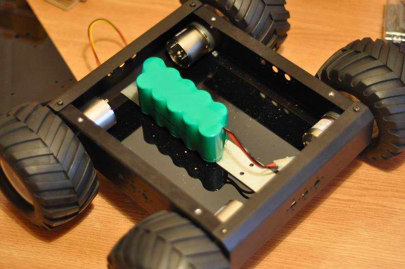
The motors are to be driven via a Sabertooth 2X12 R/C Regenerative Dual Channel Motor Controller . I am yet to see how well this performs when compared to my simple H-Bridge that I used before. The battery is a generous 12V 2800mAh from Lynxmotion.
2. February 06, 2013
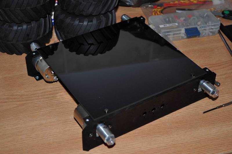
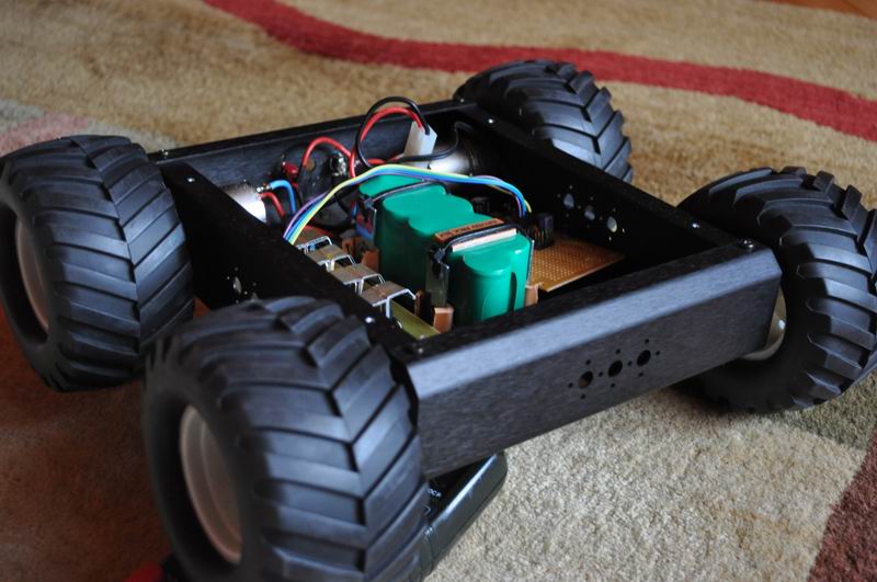
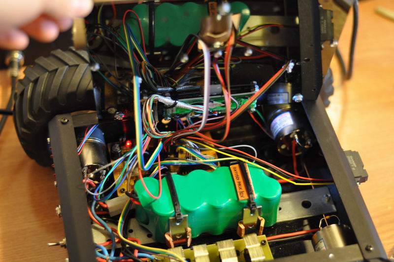
The rover’s bottom is a thin black plexiglass sheet, that looks great but can’t sustain much weight. In this case, the battery seemed a bit too heavy for the bottom sheet, especially considering high speed movements over rough terrain. So I had to build a battery holder using some steel. Hope I won’t get to replace all the original rover by the end of this project 🙂 . But this is what perfectionists usually do.

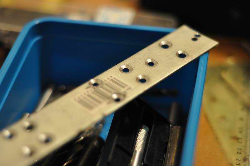
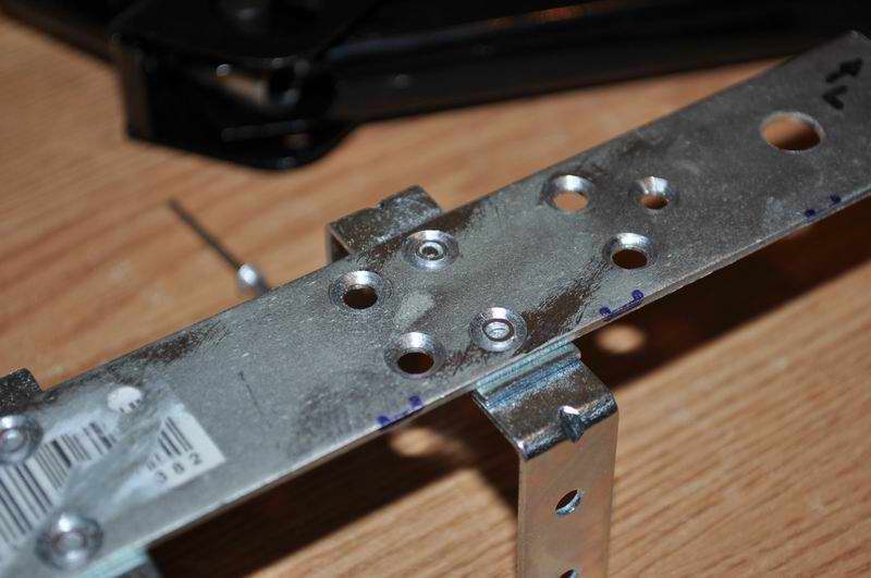
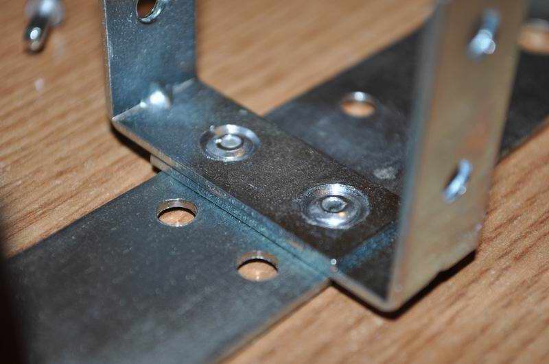
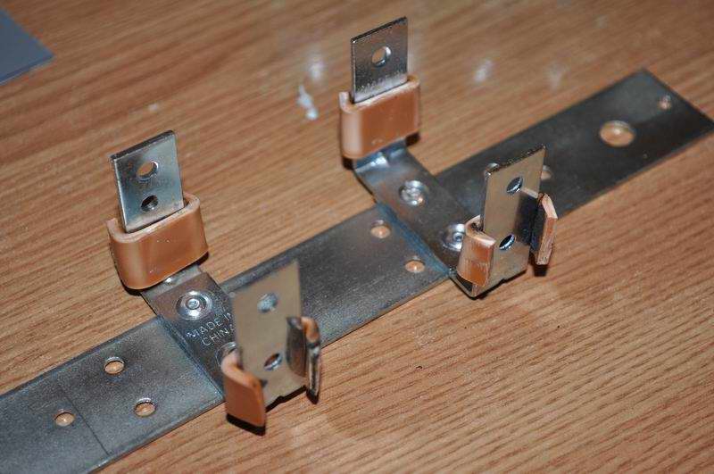
The steel support is placed longitudinally at the bottom, fixed in screws. This can be used to support other components as well, as I drilled multiple holes for that. Two U-shape holders have been fitted using rivets, this way I got no difference in level, and no sharp points to puncture the battery to be placed in this support:
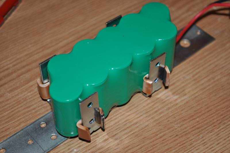
The prominent ends have been leveled with a metal file. The U-shaped holders got some little plastic spacers, made from PVC plastic heated and bended in a convenient angle. With the battery in place, here is the first motor test:
3. February 12, 2013
The Atmega128 board got a power supply, for both 5V and 3V. The latter is for the Bluetooth module and one of the GPS modules.
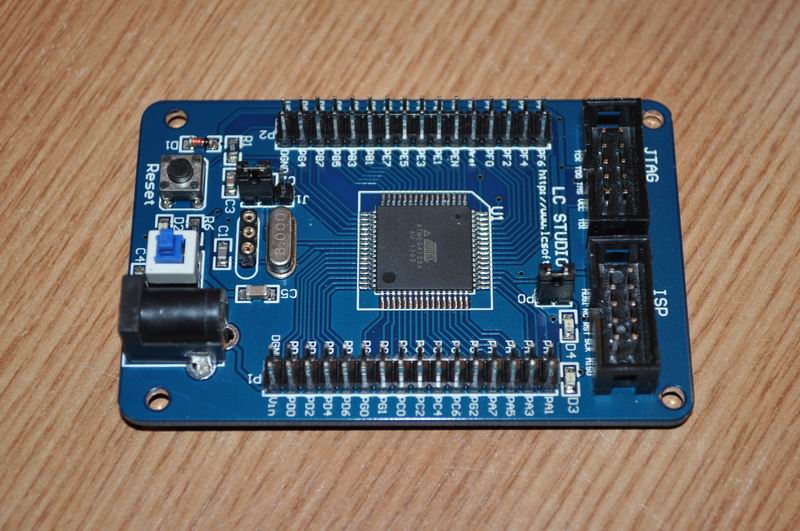
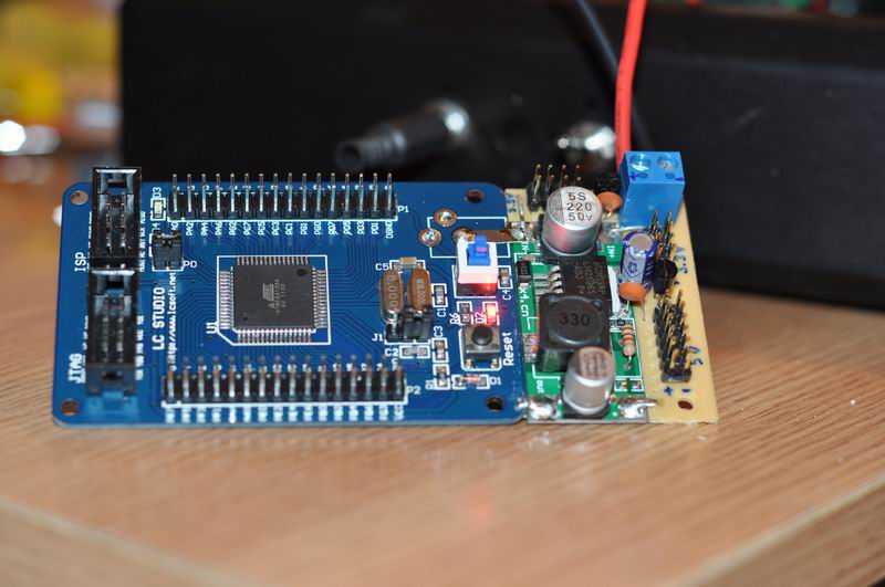
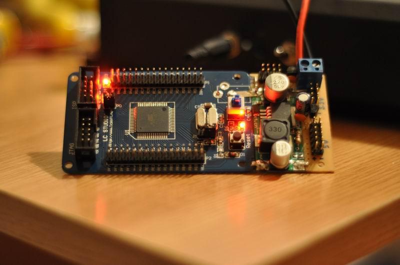
The power supply consists of a high efficiency DC-DC converter built using the LM2596 IC. There are plenty of such converters available on Ebay for just a few bucks. I replaced the pot with a fixed 1KO resistor, so the converter would put out a fixed 5V voltage. The 3V is obtained using two L78L33 ‘s. The power boards where fixed to the Atmega128 board.
4. February 18, 2013
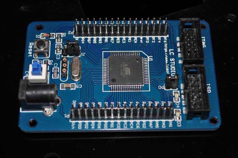
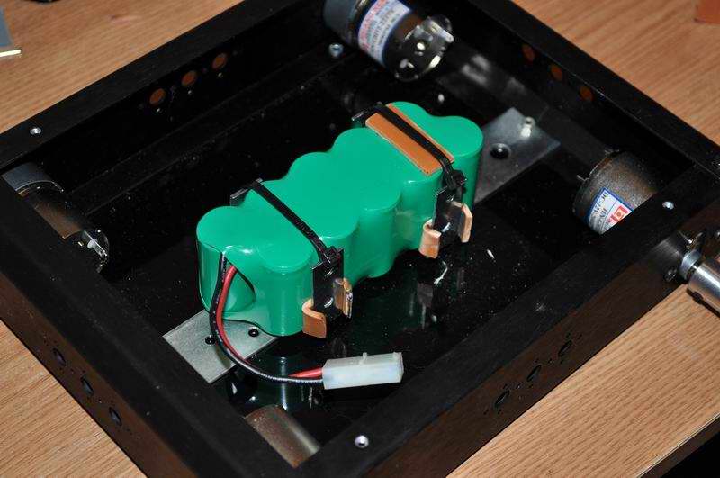
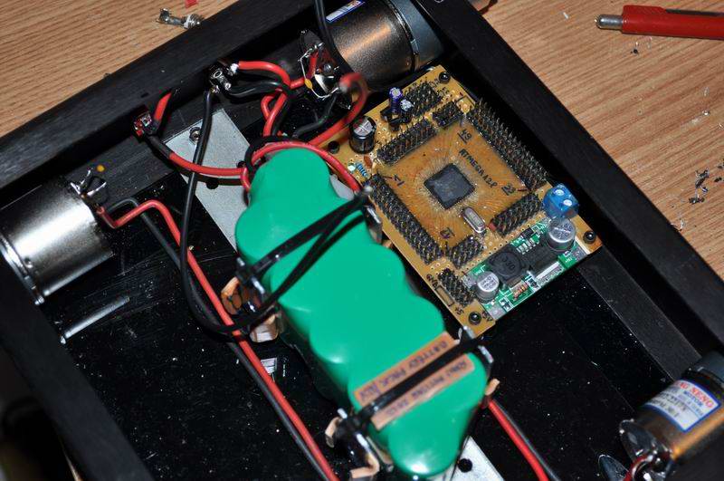
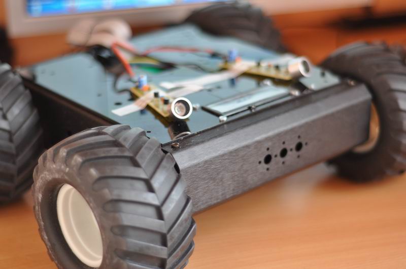
New Atmega128 board, with pin connectors including power and gnd to make connections easier. The microcontroller board has been mounted to the robot’s platform. The Sabertooth 2X12 has also been mounted. Thick wires link the h-bridge and the motors.
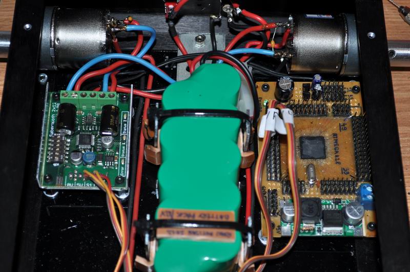
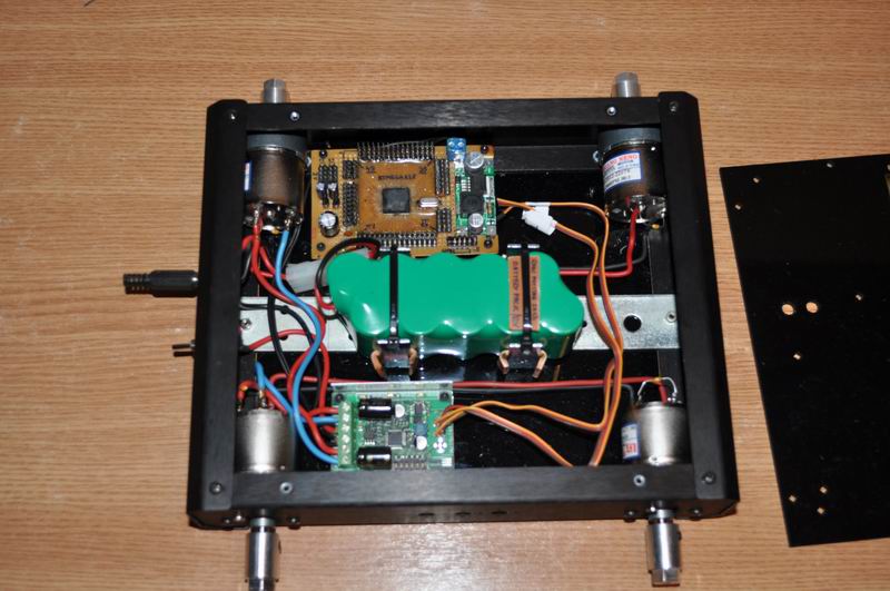
5. February 25, 2013
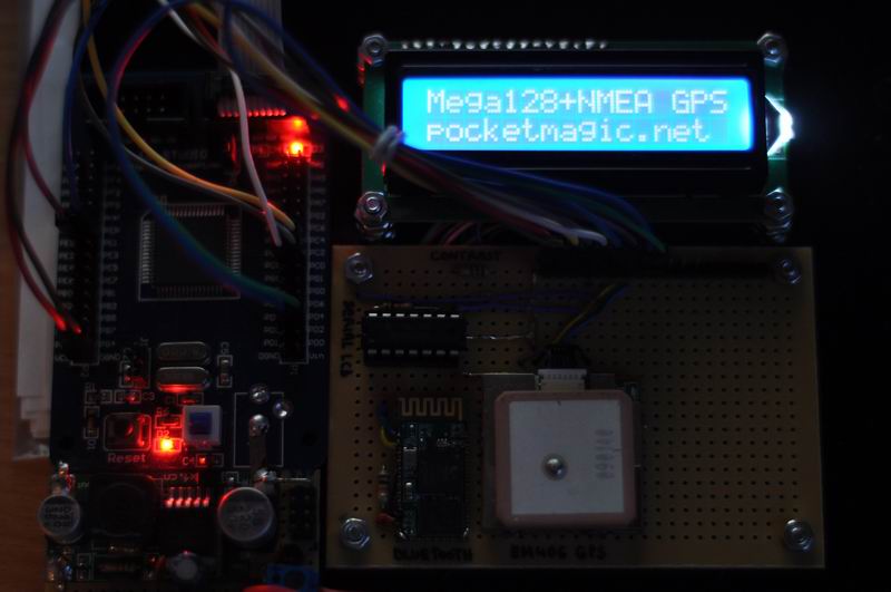
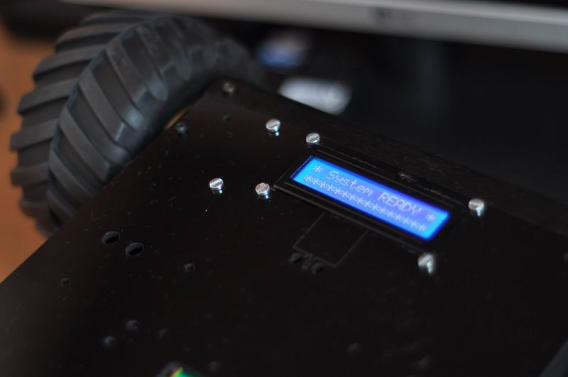
I finished the top board, exposing the bluetooth UART module and the NMEA GPS module. This will be mounted outside the robot’s body, to make sure the modules get maximum radio signal. An LCD is to provide vital information such as battery levels and other diagnosis messages.

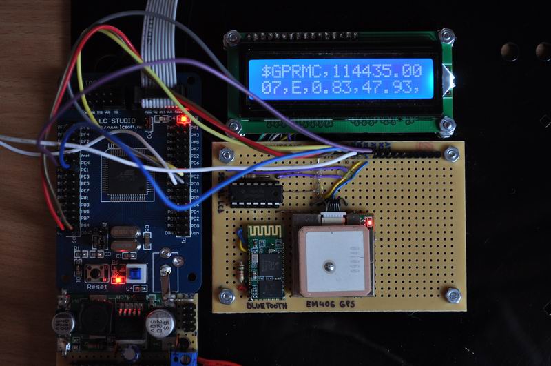

And with these last modules, I had to write a considerable amount of software. And this is only the beginning of the long road ahead:
– HD44780 LCD code . The LCD uses only 3 wires to connect to the Atmega128, using a shift register, 74HC164, to save a few IO pins.
– UART code, to handle data from the UART Bluetooth module and the UART GPS Module.
– GPS NMEA Parser, highly optimized to save memory and processing power. Also available on Google code, here.
And the first problems didn’t wait too long to show up. It appears the bluetooth module’s RF creates some kind of interference that reduces the GPS signal. As a result, having the Bluetooth module on, I can barely get a GPS fix. When the signal is good (8 satellites in use), turning the bluetooth module on will reduce the signal (3-4 satellites). Here is a demo to show this defect. The red jumper wire is used to power on/off the Bluetooth module. The “sats” value displayed on the LCD is the number of fixed satellites.
So to bypass the issue, I’ll need to rework the top-board and move the Bluetooth module at some distance from the GPS module. I was not aware of such a design requirement.
6. March 27, 2013
The Sabertooth 2X12 R/C Regenerative Dual Channel Motor Controller needs to be hooked up to an UART port. On the microcontroller board I have no free UART port available, so to simplify I plan to use a dual H-Bridge built from scratch. You can see the Dual H-Bridge here.
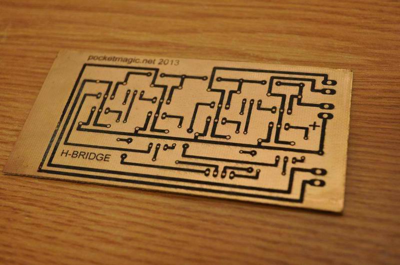

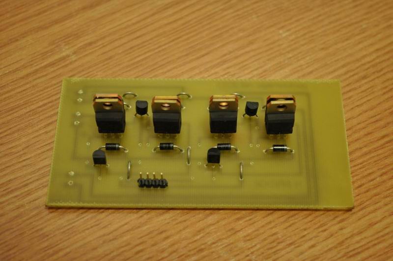
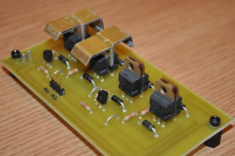
Schematics and PCB available in the Dual H-Bridge article.
The LCD has been mounted inside the chassis, must admit it looks perfect this way: low profile, high tires, black paint, and that blue electric LCD light. All combined with a highly energetic movement.
7. March 28, 2013
Following the successful dual HBridge integration, I added the Bluetooth UART module, and wrote a software for Android OS, to allow me to control the robot by using the phone. Here’s a demo video:
And a few pictures to show the final robot shape:

Next thing to do is to make the robot follow the user, AUTOMATICALLY! I’m currently considering two options, one involves using the GPS Module, send the coordinates via bluetooth to user’s mobile phone that also has GPS and can then inform the robot where it needs to go, the second option would be to use some kind of beacons, the user would carry in his/her hand (or pocket), and the robot would detect those and follow the signal.
8. April 08, 2013
As I’ve shown above, the purpose of this robot is to follow its user, and I imagined two instruments for implementing that:
1) a global localization method, using GPS. The PROs are that we can place a GPS module on the robot, and the user can have a mobile phone with its own GPS module. The phone can establish a connection to the robot using Bluetooth, and send the user coordinates periodically. Then the robot can calculate the path it needs to run, to get in close proximity of the user, and follow him/her. Sounds good, but the CONs are bad: first, the GPS errors are too big to allow us to make the robot follow the user; it would rather jump like a crazy monkey all around the user, and this is the best scenario. Another issue is also the GPS signal which is poor or unavailable indoors.
If we place a stationary GPS receiver, here’s how the GPS coordinates look like:
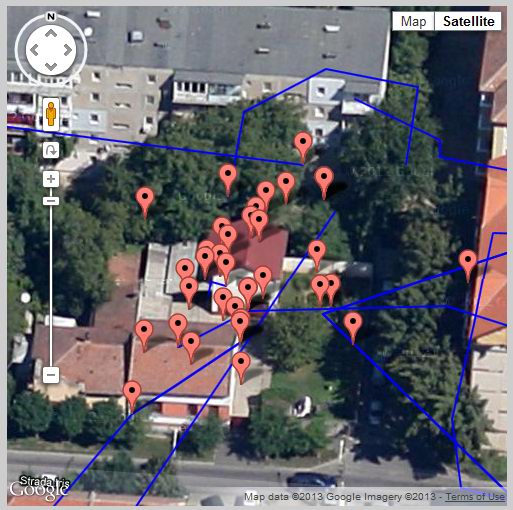
As you can see, despite the fact our GPS receiver is stationary, the localization data we receive has a tolerance of a few meters or even tens of meters, placing us on a disc surrounding the real position. This is inappropriate for the purpose of this work, so I have decided to find different means of robot positioning and orientation; this number -2- below:
2) The local method will use a closed system for localization, formed of only the robot itself, the user, and a signaling beacon. Normally the user will carry a signaling beacon (ultrasonic, infrared, radio, etc), which the robot will “see” and follow. Easy to say, doing it is of course much harder, as we need a smooth robot movement, so a lot of error compensation and fuzzy logic must be involved.
Recently I made some excellent progress using ultrasounds as a transmission method, to create a simple beacon detector. You can read more on it here.
The user needs to carry this tiny, low power ultrasonic beacon which the robot should be able to “hear” and use the signal to navigate to the target, and follow it.
![]()
![]()
![]()
![]()
These wonderful modules will not only return a signal when ultrasounds are detected, but the output amplitude is directly proportional with the actual distance to the beacon. So we’ll know both where the beacon is, and how far.
Given these tools, there are several ways of implementing the working mechanism:
a) using a single ultrasonic receiver, placed in front of the robot: the rover will need to rotate until it detects a maximum level of signal. Then it should move forward until the detected signal reaches a given threshold (so it will not hit the user, but stop right before him/her). It doesn’t really work well, as the software gets overcomplicated and the results are not as good as expected.
b) similar to a), but use a servo motor to rotate the ultrasonic sensor instead of rotating the entire robot. When the maximum signal is detected, the robot should turn towards the source, and begin moving forward . It still doesn’t solve many of the issues found with a)
c) using two ultrasonic receivers, placed some space apart, in the frontal part of the rover. Now we can make differential measurements, so it’s easy to know from which part is the signal coming from, as the corresponding sensor will have higher readings. The robot can now directly turn towards the beacon, and follow the forward direction while the two sensors give approximately similar readings. If the right sensor output increases, then it means the robot needs to turn right, to face the beacon and continue moving forward. Same case for left. A similar approach has been used in a project by Andrew Wiens :
d) using more than two sensors, ideally 8, placed at 45 degrees in a radial disposition. This would pinpoint the source more accurately, and reduce the time needed to find the beacon. Still, to simplify, I plan to go for the differential measurements presented at c) .
The ultrasonic sensors already return an output signal which is a function of the distance to the beacon / user. This can be used to measure the distance. If greater accuracy is required, we can involve infrared light in the process:
– the beacon sends a set of 38KHz modulated Infrared pulses marking moment of time t0
– the beacon immediately sends out the ultrasonic pulses
– the receiver which is a few meters from the beacon, receives the infrared pulses practically instantaneously and knows the time is t0 (using a TSOPXX38)
– the receiver registers the incoming ultrasonic pulses at the time t1, where t1>t0. By using the speed of sound in air, we can get the exact distance to the beacon.
All in one we use light to signal the start for counting, and we stop when the ultrasonic waves reach the destination.
More on this here, here or here.
9. April 09, 2013
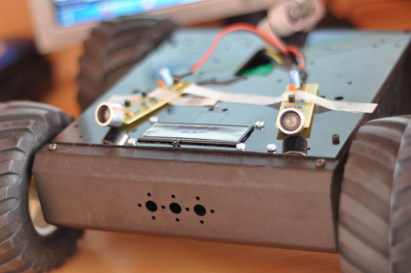
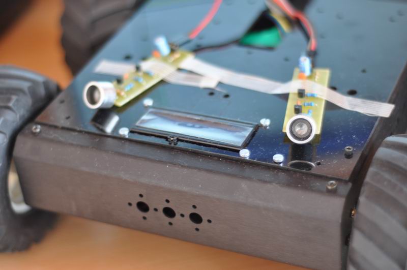
Using the ultrasonic sensors differential readings (with sensors placed in front, at angles of aprox. 15 degrees of the longitudinal axis), I got some excellent results: the robot is able to follow me, and keep track of my speed, and orientation:
The algorithm compares the readings from the two sensors and decides whether to turn left (if left sensor return higher readings), right or to move forward (if the output of the two sensors is similar).
There are some remaining issues:
– if the robot approaches a wall, and the beacon signal is coming from the back, it will reflect in the wall and confuse the robot
– no detection capabilities for signal coming from any other direction, other than the front
To solve these issues, three more ultrasonic receiver boards are needed, namely one for back, and one for each of the sides. Also the movement is a bit shaky, and this can also be improved by changes in the robot’s software code. More to follow soon.
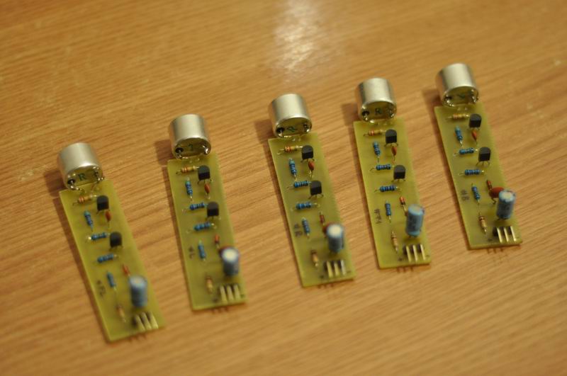
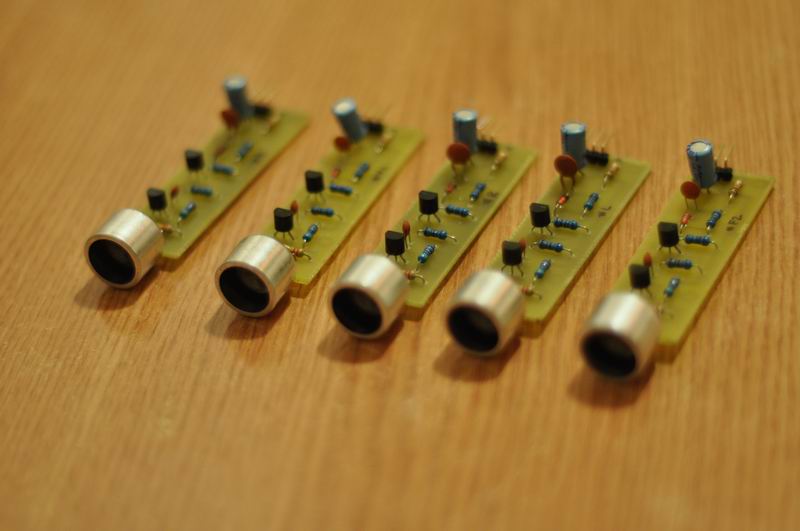
I built some nice PCBs for the ultrasonic sensors, and provided more details on Detecting an ultrasonic beacon, here.
![]()
![]()
![]()
![]()
10. April 10, 2013
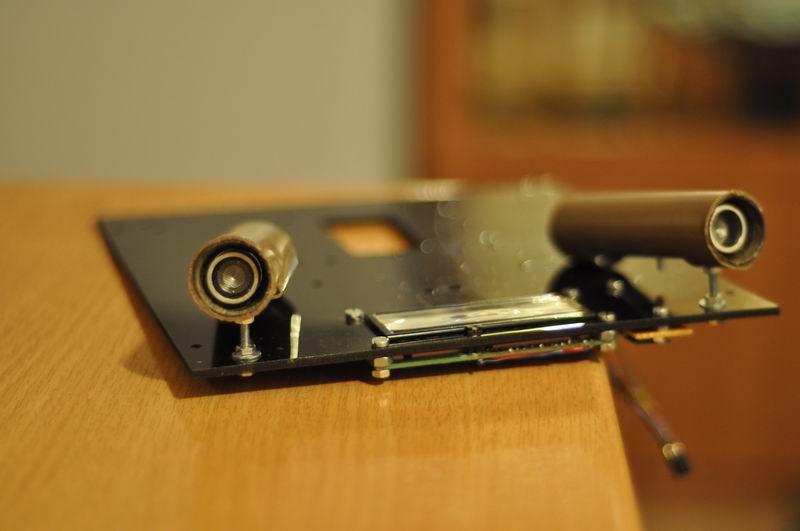
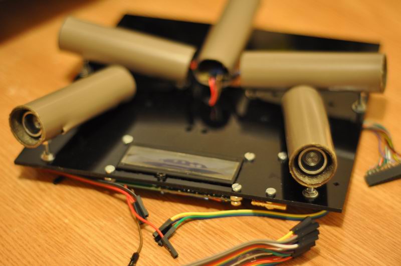
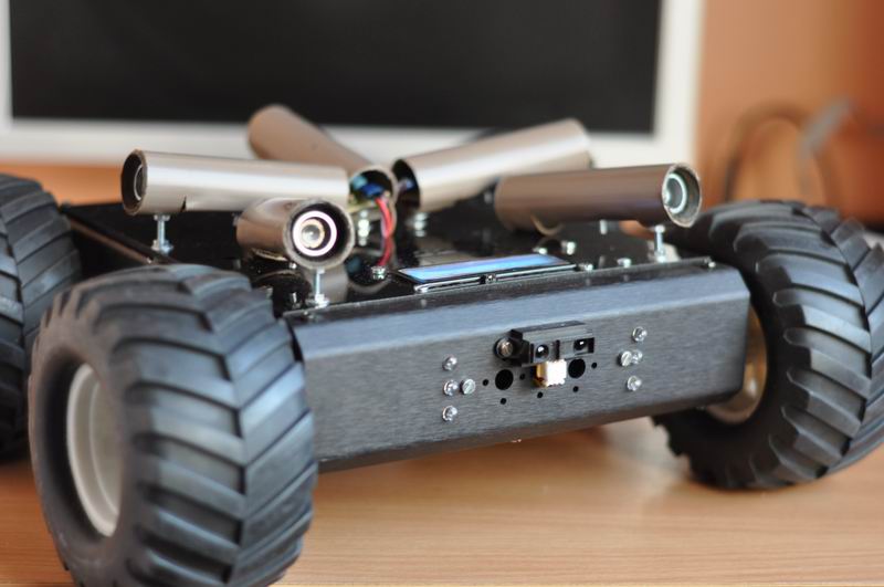
I built a total of 5 ultrasonic receivers, that are to be placed two in the front, one at the back and two on each side.
The idea is to have the robot turn around facing the ultrasonic signal, and then to make it follow the source using the two frontal sensors. The differential readings will help us decide whether to adjust the direction for left or right.
Using some PVC pipes, I built some nice and robust plastic enclosures, by heating and pressing the plastic to get the desired shapes:
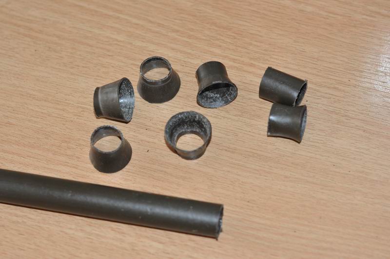


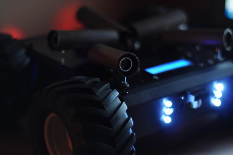
The result looks great:
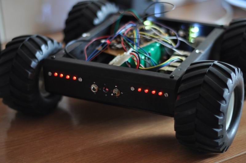
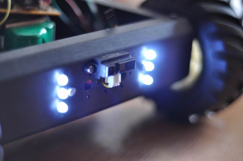
For some uber-coolness factor, I decided to add frontal white lights and back position red lights, controllable from the software (on/off). The frontal side now also houses a nice Sharp 2y0a infrared sensor, that will help avoid hitting any obstacles. So now the robot is capable to hear and see its surroundings. Love how it looks:
11. May 01, 2013
Time has come to build the TX ultrasonic beacon. This time I wanted to try something new, so here is my first PCB for SMD components:
![]()
![]()
![]()
![]()
It uses a NE556, dual timer, and is configured to emit short bursts of 40KHz pulses. You can see the circuit here:
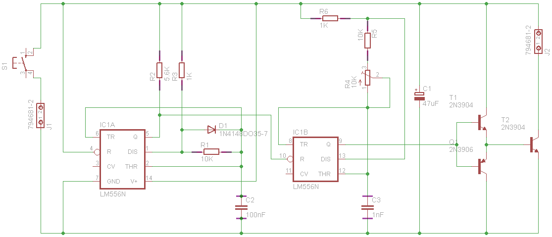
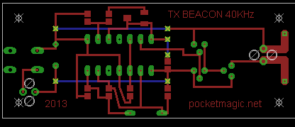
Eagle file also available, beacon TX.
A case was also needed, to enclose the 9V battery as well, and make it comfortable for holding it in the hand. The final results looks like this:
![]()
![]()
![]()
12. May 03, 2013
This project finally comes to an end, so I recorded two demo videos to show the robot following me, outdoors. A few modifications in software are likely to be done, but all in one, the work is pretty much complete:
Demo 1:
Demo 2:
13. May 22, 2013
As I am a perfectionist with all that I build, I couldn’t stay away and had to make this robot even better. So I did two things:
1) For the autonomous, human following software: I improved the ultrasonic detection algorithm, and the movement logic: Now the robot will follow its user more precisely, and the speed will vary with the detected signal: if the robots sees the user at a greater distance, will engage with a greater speed. If closer to the user, will proceed with smaller steps. The calculations are not linear, so I used some time to get the best formula. In the end I’m quite pleased, we can see some nice improvements when compared to previous two videos – so here are two new demos:
Demo 3:
Demo 4:
2) For the remote control software, where the user controls the robot using a phone, the rover now reports its frontal sensor readings (that show the proximity in centimeters to any detected obstacle), to the smartphone. So the movement commands go from phone to robot, and the sensor readings go the opposite way, from robot to phone. The Android software now allows the user to turn the lights on and off, and using the frontal distance sensor, a red line is drawn, showing the proximity to an obstacle. The robot can be controlled this way – without actually seeing what it is heading for, as this simple radar will be enough to get a clear path. Here is another demo:
3) When bluetooth is connected, the robot will ignore any ultrasonic signals from its beacon. So better separates the two modes of operation discussed above.
Resources:
Mechanisms for Combining Infrared and Ultrasound Signals for Indoor Wireless localization
Infrared / Ultrasonic beacon
Ultrasonic Source Localization
Mobile Robot Navigation
Learn about GPS
Robo-Dog on Hack A Day
Hi
this is very good project.
im also working for a project like this, can you give me the android Bluetooth app source code.
lets say we turn the robot on 50 meters away from the beacon will it still manage to reach the beacon?
This was designed to work on close proximity; your scenario is out of the current scope of this project: the ultrasound beacon has a certain limited range, 5-6 meters the most . For what you want, a different mechanism should be used, perhaps using radio waves.
Hi Radu, great project. I’m looking at making something very similar with a power wheelchair. in you ultrasonic TX circuit you say you’ve used an NE556 timer wheras in your schematic it is LM556N. what is the difference between these components? Can i use the NE556 timer? I am looking at using your design for my ultrasonic TX but have never made a PCB before.
Hi Amy . Yes you can use the NE556 !
high sir,, gud day… can u help me on making my final project entitled “human following smart shopping cart”. if its ok to you,, can we buy your project above? i mean can you provide us the tutorial of your project and we will pay you for your help..
you may contact me here…….. (belenedwin@yahoo.com) tnx… and Godbless
hellow sir,, can u help me on haw to hook up the 5 ultrasonic receiver in arduino board… can i see ur program on the follow me robot using ultrasonic beacon… tnx in advance
Hi Radu, first of all, congratulations for this project, I´ve been working on something similar, but I just found a problem, I made 2 robots, each one with it’s own control, and everything is perfect until they are close to each other, the signals begin to mix and suddenly I find two robots following one remote, Do you (or does anyone) have an idea of how could this be solved?
I am very impressed with what you have accomplished.
I am just a college student at an engineering school, and I am really interested in making what you have made here.
Could you tell me a few tips and what parts to use? Did you make the ultrasonic sensor’s circuit board yourself?
Could you please help me get started on this project?
Thank you so much.
I will be eagerly waiting for your reply.
I have tried compiling your original code you provided in Part 1. When running the resulting application I receive an exception when it tries to create the tabs. Do you have a more recent update to the source code you are willing to share?
@Dennis, see Bill’s comment under this article: http://www.pocketmagic.net/2010/01/android-dynamic-tab-control/
Thanks that solved the problem.
hello can i have the code for the ultrasonic robot. the code for the robot to move and can i use other arduino for the microcontroller?
Hello Radu,
I’m trying to replicate exactly what you did here, but i’m having difficulty with the coding of the ultrasonic receiver and transmitter. How would I code the microcontroller for the ultrasonic sensors? May I please get the code for that? Thanks.
Hi Radu! We are students in highschool and we’d like to have a look at the code you used to make the robot follow the beacon. It’d greatly help us. Thanks for your consideration.
Any suggestion about my project. I want a cell phone to make as high a sound as it can ~20kHz and then use two of your ultrasound receivers to help a robot follow it. Looks like I need a regular microphone with a band pass filter for about 20kHz. Any other suggestions, I don’t want the device to be distracted by other sounds. If the robot had more computer power I would do an FFT analysis like the flash App on my website http://www.rocksetta.com which would easily identify a specific 20 kHz sound. Any ideas?
If a cell phone could produce 40 kHz then I could use your setup.
Good day sir. I’m working with a project like this. can you help me sir? i want to make something like this using 2 geared motor only . can you help me sir? thank you. God bless.
This project is amazing! Fantastic solution for a robot that follows without using GPS.
I want to experiment on this but have one question, in a situation where there are multiple set of user/robot pair, is there a way for the robot to determine who to follow? Is it possible to embed an identification so the robot follow the right beacon? Let’s assume the robot also have a bluetooth connection with the user’s device, would this combination help the robot identify specific user? Any type of answer is greatly appreciated, thanks 🙂
@Kevin, yes it can be done. The solution is to encode some kind of ID in the ultrasonic signal. The receiver can than pick up the one to react at.
I don’t think bluetooth would work for this.
Thanks Radu, I’ve searched for ID embedding for ultrasound and came up with results like http://www.firstsignal.com/outcomes/outcome-tools/real-time-location-tracking-rtls which is a USID device, and http://www.hexamite.com/hx19flyer.htm which is a combination of RFID and USID. I’ve searched for methods on doing this with arduino but did not find anything, is it there any recommendations on documentaries relating to such topic? Thanks in advance.
Well, I’m not aware of any specific documentation, but you can go with the general approach: modulating the signal.
Thanks for the replies Radu, I’ve done some digging on the topic but since it’s out of my expertise I’ve yet to find a good example to work with, but I’ll keep digging, thanks.
can you explain about the ultrasonic receivers and tx ultrasonic beacon? like how to make the tx ultrasonic beacon? thanks in advance.
@lin all details are presented in the article. See update 10 and 11, and also http://www.pocketmagic.net/detecting-an-ultrasonic-beacon/
hello
first of all thank you , you have explained everything so well
i would love to see the code of how the uv sensors works
please can you help me with the code and mail the code to abhi.matlotia@gmail.com
what i think is when the sensor detects it puts the bit to on stage and the motor starts
thank you
@abhishek thanks, I’m glad you like it!
I think the GPS will work better if it is completely outside like in a field. Where can I get the code for the GPS location detection?
Even if outside, the GPS errors are still too large. It’s not a problem of signal (indoors vs outdoors) , but a problem of technology (GPS). I don’t think I have a final variant of the code posted here.
good day sir! this is a really awesome project. i want to create the same robot as my project. can you please send me in my email all the codes you used in this project if possible. it will be be a very big help for me. thank you in advance! please do respond.
Thanks Marvie, I’m glad you like it.
Hi there sir! Great work!
I am currently in a project that is similar to your work but it is for dextrose stand follower application. I was just wondering if you could show us the exact positions of the components in the Ultrasonic beacon in the eagle file? I’m having a hard time tracing it…..
Thanks in advance!
Can you tell me how to make a unique ID in an ultrasonic sensor? We really need it on our project. Please help us.
Salut Radu si felicitari pentru munca depusa.
As vrea sa fac si eu ceva de genul , numai ca deja am cumparat un RaspberryPi B+ si cred ca incep sa imi dau seama ca nu a fost o alegere prea buna in ceea ce priveste proiectul meu Follow Me.
Ce anume ar mai trebui sa cumpar pentru a realiza acest proiect ?
Iti multumesc anticipat pentru eventualele raspunsuri,
Sanatate
Salut Eugen. Eu am folosit un amarat de AVR, mult sub puterea de procesare a unui raspberry. Oricum, ai detalii complete in post.
Hi, could you please send me the code? im working on a project that requires the robot to follow and i really like your method of using ultrasonic sensors.
Thanks
I appreciate what you have done radu, its really nice follow me robot you made. Im making the same project now but it is for shopping cart and using infrared instead of ultrasonic, but the result isnt good enough, maybe its the sensor or the program i made. If you please to help me, can you send the source code of ultrasonic receiver and transmitter to my email yogifsyah@gmail.com? I would like to try using your method.
Thanks for consideration.
Hey…
it was awesome!!! I want to build one just like that.. for my major project.. I am from computer science branch. Please help me build one
This is a really interesting project and it’s something I think would be fun to mock up as a replica R2 unit if you’re familiar with Star Wars. I have worked with robotics and using ultrasonics as object detection and avoidance but never thought of using them in this way. As I understand it, fabric can attenuate the signal from the ultrasonic range finders somewhat. Would it be possible to put the beacon module in a back pocket so it isn’t visible or does that dampen the signal too much? I’m also looking for your schematic for these ultrasonic receivers but don’t see one. I’m wondering if I could use some of my HC-SR04 rangefinders and take the appropriate parts off of those to make these other sensors. I can get a whole mess of them for very cheap.
Hope you’re still managing this thread. Thanks.
Hello Steve, indeed, I took my ultrasonic transceivers from HC-SR04 modules.
Hi Radu, such an Amazing project! I really want to built you project, so if you could please please please, help me to get things started particularly the code for controlling the robot from an ultrasonic signal. my email: mplfu2003@yahoo.co.uk Many many thanks, 🙂
Thank you. The functionality presented was the result of very intense research effort. The code is not publicly available , but we might work out a licensing mechanism if you are interested.
Please do email me back ,
i’d like to do this project for following-human-IV Drip.
list the components that involve.
Hi Radu,
Amazing 🙂 I’m looking to do a project like this, but have zero experience with electronics. I’m building a Mouse Droid from Star Wars and want it to follow a group of stormtroopers. Would you be able to commission the electronics required? Many thanks, and again, great job!
Aaron
Might be possible, I’ll think about it and send you a message.
This is really amazing, I do not know much about coding and electronics but I am a 3d designer. I was looking to make a motorized robot with wheels like yours that can follow a person via signal/beacon for a project. Could that design of yours be made bigger and to withstand a decent amount of weight on top? I’m sure the wheel base would have to get bigger, but your concept is exactly what I’m looking for. From what you describe it sounds like to got it to follow a beacon the user would have and keep a certain set distance away, also able to make speed adjustments and recognizing starts and stops. Please email me so that I can learn about the components you used and the coding. Thank you
Radu,
what if you have to walk through a corner?
that robot will hit the wall or not?
hey Radu …
i can’t find an ultrasonic symbol in live wire …
what software did u used ?
First of all I’d like to say that you are awesome I’m a quadriplegic and I work on a lot of things with modified tools and I’ve even made a wheelchair remote control that I can drive around it’s kind of ridiculous how many tools I have stuff around in different places on my Mobility Scooter now I already have several platforms of electric wheelchairs that I have been going to make remote control maybe even one with a scoop bucket or forklift but definitely with a basket or toolbox made it to the top the question is would you be willing to sell me the electronics so that I can make one of these wheelchair follow me around I’ve been trying to take the time to learn Arduino but so far have only dabbled in electronics lately I’ve been doing really well fixing a stereo receiver remote camera DVR and my welder I probably saw her something just about every day please let me know thank you very much
Oops I meant solder something electrical thanks again