
Purpose of this article:

1) to learn how to connect the Micro controller in a simple circuit and how to power it
2) to see how to create a simple programmer (a device to connect the micro controller to a PC for uploading software)
3) to present a simple software program in C that controls a series of LEDS
4) to show everything in action
Note: its my first time when I’m working with micro controllers. The info presented here might be inexact, but not incorrect, since I will stick to my findings and to the easy path for a beginner.
All that is presented below was the result of one day of reading, soldering, testing – a good score I would say.
Short Intro and Motivation
Since I’m a C++ developer for Embedded Devices, small processing units were always a strong point of interest for me. Furthermore, building a robot for my bachelor degree, a few years ago, required getting over serious hardware limitations related to power consumption and weight. So I’m still looking for a way to perfect my robot, and to extend its functionality, and the microcontrollers look like a very interesting approach, to say the least.
For a start, I had two micro controllers at hand: the popular ATMega8-16PU and the not-so-popular PIC24FJ64GA002. The first one I’ve bought on Ebay from a very good seller in Thailand:
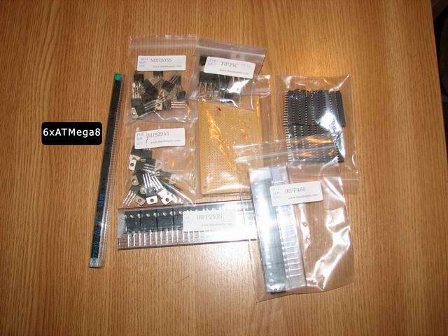
For this article I will be targeting the ATMega8, since it gave me excellent results, thanks to available documentation. Can’t say the same about the PIC.
So let’s start:
Our first ATMega8 circuit
The ATMega8 is an excellent micro controller:

|
28 PINS (23 for Input/Output !!!) 8-Kbyte self-programming Flash Program Memory 1-Kbyte SRAM 512 Byte EEPROM 6 or 8 Channel 10-bit A/D-converter Up to 16 MIPS throughput at 16 Mhz 2.7 – 5.5 Volt operation Its datasheet is available here I suggest you download the ATMega8 image to the left and print it, since you will need it often to consult the PIN layout when doing your circuit. |
The Input/Output pins are important when it comes to how many devices you want to connect/control/use. To control a simple LED you will need to use 1 PIN (for output). To control a temperature sensor, you will need another PIN (for input).
To do a simple circuit and power the micro controller, first thing you need to know is that you need a stable 5V power source. The best way to achieve this is to use a regulator like the 7905/7805. This component has constant output regardless of the input current – in regards to some given boundaries, of course.
Here is the circuit. I suggest you use sockets for the ATMega8, to easily change the chip on your board.
By implementing the schematics above, you’ll have the microchip powered. But you’ll need to program it in order to have a useful result.
Developing the Atmega software
Let’s try something simple – like controlling a LED on/off.
For this, we need to attach the led to any of the ATMega8’s available I/O pins.
I’ll use Pin 28 named PC5. This pin is part of the PORTC set of 7 pins PC0 – PC6. Notice there are other sets of pins like PORTB (PB0-PB7) and PORTD (PD0-PD7).
So the wiring is like this:
Next you’ll need a C compiler for the ATMega8 and a software programmer that will upload the compiled code to the micro controller.
For the compiler I’ve used AVR Studio from ATmel. Download the 3 files below and install them in the given order (the avr studio itself and 2 additional service packs):
1 AVR Studio, version 4.13, build 528 (73.8mb)
2 AVR Studio 4.13 SP1 (build 557) (37mb)
3 AVR Studio 4.13 SP2 (build 571) (45mb)
For the uploader I’ve used AVRDude that comes with the WinAVR package:
WinAVR
As soon as you’ve installed everything, start AVR Studio. You’ll get a page like this:
Click on “New Project”, and select AVR GCC, then add a project name “TestLED” and select a location to store the new project’s files:

Click Next, and in this new page you can select “AVR Simulator” and to the right under Device, select ATMega8 as show below:
Simply press Finish, and you can start writing code:

First things we need to know:
#include
Will include this library in our project so we can access basic Input/Output functions and macros.
int main()
is the entry point of our program, here is where the program execution starts.
So, first thing to do is to set the PORTC as output. For this we’ll use a special register named DDRC:
DDRC = 0x20;
why 0x20? Let’s have a look in binary:
| PC6 | PC5 | PC4 | PC3 | PC2 | PC1 | PC0 |
| 0 | 1 | 0 | 0 | 0 | 0 | 0 |
Basically we set a value of 1 to the position associated with our target pin.
To set all pins to output, the value would have been:
DDRC = 0x7F (in binary: 1111111)
To control other ports (B or D) you can use DDRB or DDRD in a similar way. At this point you should consult the micro controller’s datasheet available here.
Next thing to do is to turn the led on and off by code. We want this in an infinite loop, so here’s the approach:
DDRC = 0x20; //PC5 set to output
while (1) //forever
{
   PORTC = 0x20; //set PC5 on . again computed in binary
   delay_cycles(1000); //a short delay to keep led on
   PORTC = 0; //all C Pins off
   delay_cycles(1000); //a short delay to keep led off
}
An even better approach that doesn’t interfere with other PORTC pin’s settings would be:
DDRC |= 0x20;
while(1)
{
	PORTC |= 0x20;  //set 1 on first position, or simpler: PORTC = 0x20;
	waitd();
	PORTC &= 0x5F; //remove position 5 value, or simpler: PORTC = 0x0;
	waitd();
}
After the code is ready, press Build in the menu. It will produce a .hex file, in this case testled.hex
A parallel programmer for the ATMega 8
A programmer is a hardware interface that connects the micro controller to a PC.
On the PC you create a software program, that you can then upload to the ATMega8 using the programmer. It’s quite simple.
To make things easier, I’ll describe how you can create a parallel programmer, but this will work for you only if your computer has a parallel port since that’s where you need to connect it. If it doesn’t, you can purchase an USB2Parallel adapter or build an USB Programmer directly (you can use this)
Use any of the three variants below. My first programmer was a BSD parallel programmer.
BSD Parallel programmer
The first one is called bsd, probably because it was originally available at AVRPROG program for FreeBSD.
For this parallel programmer you’ll need a LPT 25pin connector and 4×470 Ohm resistors. This is the way you need to make the connections for the BSD type parallel programmer:
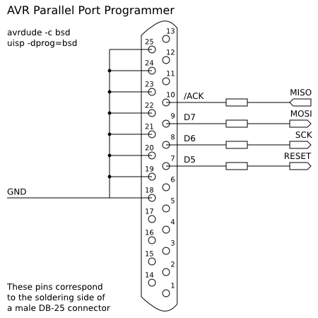
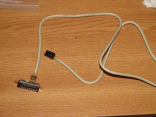
Here’s how I’ve managed to set it up:

To download the previously generated .HEX file to the atmega8, we will use our Parallel BSD programmer. Go to WinAVR folder, and enter the BIN subfolder. Copy testled.hex here and make sure your parallel programmer is connected.
Type in this command:
avrdude -p atmega8 -c bsd -U flash:w:testled.hex:i
stk200 Parallel programmer
This was my second build. It behaves like the STK200 AVR Starter Kit, and it is also compatible with the PonyProg software. The design is simple:
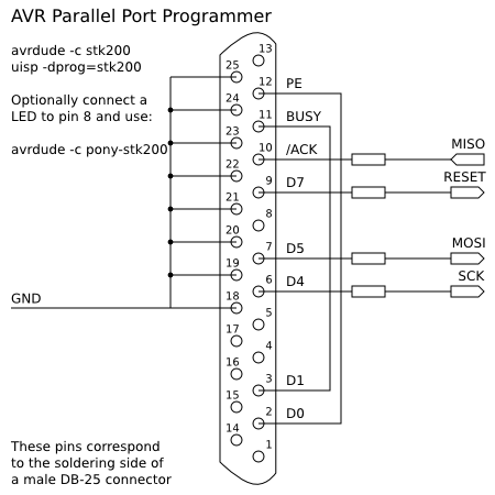
To write the hex you can use:
avrdude -p atmega8 -c stk200 -U flash:w:testled.hex:i
DAPA Parallel programmer
I newer built this, as not long after the stk200 I moved to usb programmers. Dapa, which means Direct AVR Parallel Access cable, can be seen below:
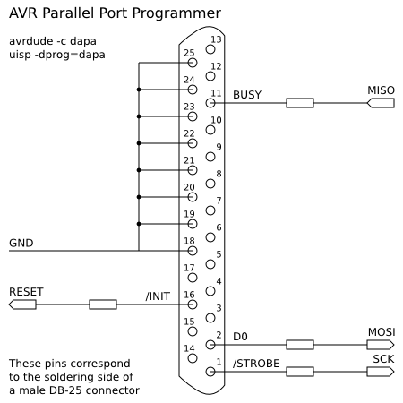
The command to write the hex is:
avrdude -p atmega8 -c dapa -U flash:w:testled.hex:i
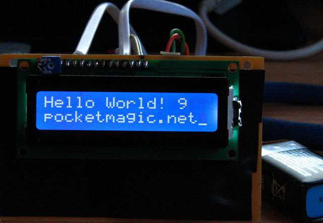
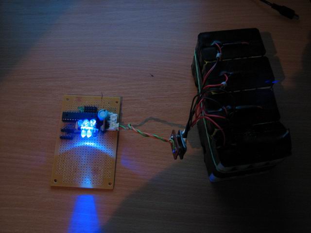
The results:
After the avrdude command, if everything goes right, you will see a progress bar indicating the code upload to the micro controller:
As soon as the software is uploaded, the code will be automatically executed.
Sometimes you might need to disconnect your parallel programmer after the code has been uploaded!
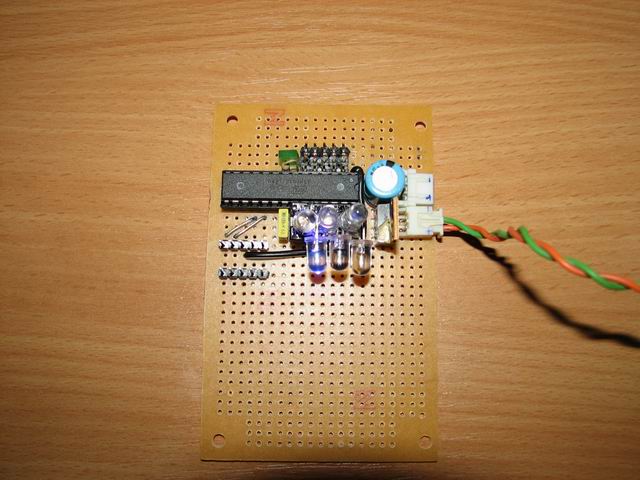
Here’s my ATMega8 micro controller and several leds connected to multiple I/O pins:
Hope you find this useful. Thanks go to:
elforum.ro and the good people there
Society of Robots tutorials
CrazyTB’s blog
I’ve already built a very stable and flexible 4bit HD44780 LCD interface for the ATMega8, so stay tuned for the next article.
You can download my code here: testled.zip
The fusebits
If you need to learn more on how to correctly set the fusebits, see this article.

I have something in mind that is why does not need Crystal atteched ATmega8 in your circuit. also if I make my test Kit from you, is there no problem ?
I have good reply from you as soon as possible. most of atmega test kit has crystal on it. but your is not.
thanks. best regard. Lim.
please email me. after making my kit from you and I will test my kit above your document step by step.
I wasn’t using a crystal here, because I was relying on the internal oscillator.
With the default LFuse configuration, my Atmega8 was running at 1MHz.
Later I added a 16MHz crystal, I’ll post the new details soon. Good luck!
Hi. Radu.
Can I ask new one that is how to change clock 1mhz to 8mz with avrdude ?
do you try this on atmega8 ? if you know a method that I ask, plz mail to me.
I try to this. because 1Mhz is so slow I can’t make any project.
have good day.
Hi Lim,
To set your Atmega8 to 8MHz (from default 1MHz), use:
avrdude -p atmega8 -c stk200 -U lfuse:w:0xe4:m (assuming your programmer interface is stk200) or
avrdude -p atmega8 -c bsd -U lfuse:w:0xe4:m (for BSD)
I’d also suggest you read the info here:
http://elecrom.wordpress.com/2007/10/15/configuring-avr-fuse-bits-for-clock-selection/
I’m happy for you, I just have done my test from above. The result I saw Led blink speed is so fast. I’m satisfied. best regard.
Great thanks for this article! It was excellent for my first steps in uC!
Lim, Polej, I’m glad it helped.
Salut. Iti multumesc pentru acest tutorial. Sunt incepator in acest domeniu si acest tutorial m-a luminat cat de cat cam cum sta treaba cu microcontrolerele. As fi recunoscator daca ai avea amabilitatea sa imi raspunzi la cateva intrebari pe adresa de mail.
I just want to ask if it is possible to create a code that can SIMULTANEOUSLY produce an output from PORT C. I.e. PC0 outputs blinking light while PC1 output depends on the input from PAO. My code doesn’t produce the desired output simultaneously. Can someone help me? Thanks in advance.
while(1)
{
on(1);
_delay_ms(5000);
PORTC |= 0x02;
_delay_ms(10000);
PORTC |= 0xFD;
}
}
void on(int a) {
while(a==1) {
int temp=0;
temp = PINA&0x01;
if (temp == 0)
PORTC = 0x01;
else {
PORTC = 0x00;
return 1;
}
}
}
Marian, radu.motisan@gmail.com , dar poti sa ma intrebi si aici, in engleza, daca pot raspund iar restul cititorilor ar putea beneficia si ei de informatii.
patrick,
to set 2 pins to ON simultaneously, you must do it with a single PORT command. if you do this by calling PORT for the first PIN and THEN another PORT for the second pin, it won’t be simultaneous.
so supposing you want to trigger PC0 and PC1, you need to do:
//–setup part–done only once–//
DDRC |= (1<<0); //set PC0 as output
DDRC |= (1<<1); //set PC1 as output
DDRA &=~(1<<0); //set PA0 as input
//–trigger PC0 and PC1 simultaneously:
PORTC |= ((1<<0) | (1<<1)) ;//set both PC0 and PC1 as HIGH
What this does is to set the bit mask associated to PORTC so only the first two bits are set to 1 and the rest unaltered.
To enable PC1 based on PA0 status, you need to do:
int i = 0;
while (1)
{
_delay_ms(5000); // small delay
if (0!= (PINA & (1<<0))) //PA0 is HIGH
PORTC |= (1<<0); //enable PC0
else
PORTC &= ~(1<<0); //disable PC0
if (0!= i)
PORTC |= (1<<1); //enable PC1
else
PORTC &= ~(1<<1); //disable PC1
i = (i+1) % 2; // i goes like: 1,0,1,0,…
}
Does your code work for AT90CAN128-16 microcontroller? thanks
Patrick, you need to compile it for the AT90CAN128.
What exactly do you need to do?
Hey where do you get all your electronics like resistors, regulators etc.?
various shops. ebay. etc.
For more tutorials with the atmega8, I highly recommend http://www.societyofrobots.com/step_by_step_robot.shtml.
Hi Steven, I’ve already included the link at the “Thanks go to:” section in the post above, but good to have it underlined here since it is a very useful website.
hi i need help in generating random numbers for my atmega microcontroller.. im using avr studio and time.h is not of their defaults which means i can’t do the “srand(time(NULL));” command, i tried to obtain one, but multiple compiler errors just occured.. please help..
Hi Charles,
Luckily, I got the time to write a short article on random numbers, to help you generate your own, without any external libs.
Please see:
http://www.pocketmagic.net/?p=1113
If you have any questions, let me know.
great job with the article! but i have some questions.. lets say i have to generate 3 values only(0,1,2) how do i do that?
Well you can use the mysrand and myrand functions defined in the article. Then do the following:
int value1, value2, value3; //the 3 values you need
mysrand(123);
value1 = myrand(256); //0..255
value2 = myrand(256); //0..255
value3 = myrand(256); //0..255
The only issue is that each time you will use the code above, you’ll get the same initial values. So the solution is to read one of the a2d ports and init mysrand with that value.
Or if you need the 3 values all over again (in a loop) do something like:
mysrand(123);
value1 = myrand(256); //0..255
value2 = myrand(256); //0..255
value3 = myrand(256); //0..255
mysrand(value1 + value2 + value3);
Hope this helps.
got it! tnx a lot!
intrebare tampitzica .. vad ca pe scheme nu ai pus oscilatoare. Sa inteleg ca are oscilator intern? trebuie sa scri linii de cod pentru a indica faptul ca e intern? As vrea sa fac o aplicatie in Codevision AVR pentru un senzor SHT11 si un LCD compatibil hd4478si sunt curios daca partea asta de oscilator si alimentare MCU da batai mari de cap. aplicatia am impelementat-o deja pe o placa de dezvoltare Cerebot cu atmega64 de la digilent dar as vrea sa o fac de la zero folosind un mega8. Multumesc.. si felicitari pt blog e super misto 🙂
mersi! 🙂
atmega8 are oscilator intern setat by default pe 1mhz. am mai multe articole cu atmega8, arunca un ochi peste ele.
pentru alimentare atmega8 foloseste 5v dintr-un L7805. Succes!
Hello Radu!
Thanks for the great tutorial!
One question: In order to program the microcontroller, it has to be powered from 5V when connected to the parallel port?
Thanks!
Hello Malin, thanks. Yes you need to power the MCU when using the parallel port programmer.
I am working on a microcontroller project at a undergraduate level. The microcontroller used is ATmega8. How can I write a program in c where a load sensor like strain gauge will be used with this microcontroller.
Does your programmer method support atmega8L running on 3.3volt?
Pingback: PocketMagic » Multitester using ATMega8 and HD44780 LCD
Salut Radu!
Iti scriu in engleza ca poate mai vrea si altcineva raspunsul.
Thank you very much for this tutorial. It is good explained!
I have few questions:
1. Programming using the USB programmer is the same as the Parallel port? I mean, I shouldnt do any settings in the AVR Studio? I am asking you that because I don’t have a parallel port…
2. I saw that you gave us 2 example of codes. In the second you used bitwise operations. Does it matters if I use bitwise operations or ‘normal operations’?
3. I can use every port I want to i/o?
Iulian , salut initiativa ta, doresc si eu ca aceste comentarii sa ajute comunitatea.
1. The parallel port is a rare find in current computer configurations. To build an USB programmer, I suggest this resource: http://www.fischl.de/usbasp/ . Many users reported very good results in using it.
2. The sample I’ve posted has a purely didactic purpose : flashing a led. In case you need help with a given task regarding microcontrollers, feel free to post any questions, and I’ll try to provide hints or ideas
3. Almost. The VCC, VREF and GND ports are not usable for I/O. Also when using a quartz crystal, other two I/O pins will be “sacrificed”. Best approach would be to consult the datasheet for any given microcontroller.
Hope this helps!
Radu
Hi Radu,
I found that my motherboard has a COM (Serial Port). In this case, can I use Serial Port (9 pins) to flash the atmega? Is there any simple way to flash it using serial port like parallel port (few resistors)? Does it works with avrdude?
Do you know any tested diagram for that? I’ll search one too.
Thank you!
Hi,
I found a diagram for a serial port programmer. It’s pretty simple. Link: http://ionutstoica.info/wp-content/uploads/2010/07/Clipboard01.jpg
For +5v supply source we can use the +5v line from the pc’s molex connector.
Have a nice day!
Hi Iulian, sorry for the slow answer. I’m still using my good old parallel port programmer as presented in this article. Slow but easy.
Hi Radu, I’m new in microcontroller programming. I made a board with an Atmega8 and some LEDs. Implementing your programcode worked very well. Congratulations. After that I tried to make a light organ on the PORTC of the Atmega. Trying several combinations all worked on AVRStudio simulator but on the board only the PC0 port worked. Here is one of the programs
#include
#include
void waitd()
{
register unsigned short int t = 0;
while(++t) _NOP();
}
int main()
{
DDRC |= 0x3F;
while(1)
{
PORTC |= 0x01;
waitd();
PORTC &= 0;
waitd();
PORTC |= 0x02;
waitd();
PORTC &= 0;
waitd();
PORTC |= 0x04;
waitd();
PORTC &= 0;
waitd();
PORTC |= 0x08;
waitd();
PORTC &= 0;
waitd();
PORTC |= 0x10;
waitd();
PORTC &= 0;
waitd();
PORTC |= 0x20;
waitd();
PORTC &= 0;
waitd();
PORTC |= 0x01;
waitd();
PORTC |= 0x02;
waitd();
PORTC |= 0x04;
waitd();
PORTC |= 0x08;
waitd();
PORTC |= 0x10;
waitd();
PORTC |= 0x20;
waitd();
PORTC &= 0;
waitd();
PORTC |= 0x3F;
waitd();
PORTC &= 0;
waitd();
}
return 1;
}
If you have time please check it.
Thanks
Hi Levy, it appears the code above turns on different PIN combinations , then OFF, and seems correct.
What exactly doesn’t work for you?
On simulator works perfect, but when I implement it, its working only with the PIN PC0, its turining on and off but the others don’t.
Thanks for reply
hey bro.. in my project i want to on the timer on 1 input pulse and then want to off it on another pulse..
so that i can have the total time elapsed… can uplz write a code for me plz….
Pingback: AVR forum :: need parallel programmer circuit for atmega8 | LED World
Hi Radu…,
very impressive site. I am not familiar with C compiler, but doing a lot in assembly language. would you pleased giving an example in asm code.
thanks
its greate example .. tnx for your support
I want to make 5 channel IR remote control from AT mega 8 So Emphases requested you to guide proper advice about how it makes. I also want to that AT mega 8 can also may give 12V DC constant and 230V AC to pin 7.
Kindly do needful and oblige.
Thanking you
Hey can any one tell me how to program 8051 series MicroController ??
I am using at89C52 UC and want some help how to program in C. any help guyz ?
who can write a software to programming ATmega8 please contact me
Pingback: Cheap AVR USB Programmer « PocketMagic
Great article man!Really helped me!So i do not need a special board to upload the hex file to my atmega!i thought i must buy i board..
I am working on the project of ‘intelligent transportation system’ based on colour senser.i have added RF transe receive for communication between two buses.In which one bus is having human driver and it wll generat different color at the back.Another bus will follow the main bus by sensing that color.Now i want to know how can i modify my project?
Please help me as soon as possible.
THANK YOU
what exactly do you need help with?
sir, actually i wanted to know that what different kind of works i can take with 3 wheeler robo(bus).i am using ATmega8 controller.project is based on color sensor and i am using RF trans receive also.I wanted to add more applications.
On thing I needed to do was add the function prototype for void lcd_string2(char *szFormat, …); to the header file because it is not there. Not a problem but thought you might like to know.
Hi,I want the article of c language programming that help me to use basic extension or code use in the atmega8 controller to develope my logical thinking. I am new to c-programming but I am very familiar with assembly language programming. so plz tell me about how to use asm in atmega8 and give me codes ..Thanks
hi i am using a ATMEGA8 AND 8 LED(1 2 3 4 5 6 7 8) on condition for led (1and8)(2and7)(3and6)(4and5)onl port B please give me a coding for codevision avr software
time duration 1 sec on off process for led
Dear Pranjal,
Please read my article and try the attached sample. It is very easy and you will learn how to control the leds. I have many more articles on microcontrollers on this blog, read them carefully as they can prove useful to what you are doing: http://www.pocketmagic.net/?tag=microcontrollers
“Give a man a fish and you feed him for a day. Teach a man to fish and you feed him for a lifetime.”
can we take power from two terminals of USB????????????
Yes. It will give you 5V!
Hi, i am using a atmega8 avr iRobot kit,,,it looks totaly same as of dis article…..i hav workd out wid lEDS, its been dne ..
i want some c sorce cods to work on it…lyke line follower (or) obstacle avoider (0r) mobi controled bot…(or) any other bots…
can u pls provide me codess……if can plz mail to my id(jagu.7670@gmail.com).
@jagadeep see my bluetooth android controlled robot. It’s probably what you need
Can u plz provide me sme other links..useful for learning different coding techniques for atmega8…
I want to connect a usb male connector to ATmega8L for programming .how can i connect it
plz i need the circuit connect of that.
I want to connect a usb male connector to ATmega8L for programming .how can i connect it
plz i need the circuit diagram of that.
I NEED CODING IN avr STUDIO 4.0 for line maze solver using right priority using AVT ATmega 8
@patel , you came to the right place. Here you can read my articles and learn how to do it. Good luck! 🙂
Thanks a lot man…
i have been trying to get started with atmega8 for 3 weeks,n now its up n blinking 🙂
got some errors while compiled ur testled.c with gcc-avr in linux,but directly uploading the ur hexfile uworked…thanks again 🙂
Getting the leds to blink the first time is a great sensation. Glad to hear this helped.
sir,how we can burn program to ATmega8?
im doing a project on speed tracking using the atmega8.. here i need to use 2 leds and a counter as inputs and the outputs are a lcd(16X2)and an alarm… when the 1st led goes off the timer starts and when the 2nd led goes off the timer stops.then this time duration is used for the calculation of speed and compared with a desired speed and then displayed on the lcd along with some suggestions… the alarm starts buzzing when the calculated speed gets above the desired speed.
i need help for the programming… plz help.
i want to learn atmega8 programming what to do learn it in least time…? hope you will provide me solution…
i have a problem with atmega8 i use BSD Parallel programmer but i got error of
avrdude: can’t open device “giveio”
avrdude: failed to open parallel port “lpt1”
very nice It works i have tried
hi i have robosapiens AVR Stimulator ATmega 8 kit with AVR studio 4 i want to code it for line follwers pls send me code at mymail
i have a query that why we use crystal oscillator outside again?
and which oscillator is in atmega8 is it rc or crystal oscillator?
and also i have made lpg nad alcohol detector wireless for my clg project i want to know why we use rf transmiitter and reciver of freqcy 433mhz…………plase rply soon
@ Rodu Motisan.
Sir!
I was reading comment and i noticed that you are doing great job.I really appreciate your good sincere effort.
hi, I want to programme my ATmega8A…..can u help me please?
hi! I installed winavr 20100110 on windows 7. but when i tried to open it, it just flashed command prompt once. It didn’t open. please help me with this problem. Thanks in advance.
please send the coding of the temperature controlled dc fan using atmega8
Pingback: Introduction to STM32 microcontrollers - PocketMagic
Pingback: Featured by Atmel - PocketMagic
Hi
I am following your tutorial about Robotics using ATMega microcontrollers . I have the complete kit of making a robot controlled by android phone from ATMega .
I searched a lot about how to program it . I made the connections and it (as per the hour) once connected to power (either wall socket or USB ) functions and tiers rotate randomly .
I installed all drivers and softwares recommended here http://www.pocketmagic.net/first-steps-with-micro-controllers-atmega8/ . I got the code from your website but the problem is that when i copy/paste the code it doesn’t build but when i ran it directly (by opening the folder using AVR stduio) it builds . I am stuck here and seek your help .
// ATMega8 Perseus – 3 Command module
//
// (C) 2010 Radu Motisan , radu.motisan@gmail.com
// http://www.pocketmagic.net
// All rights reserved.
//
#include “globals.h”
int g_nMove = 0, g_nTurn = 0;
void uartRxHandler(unsigned char c)
{
char xs[255] = {0};
sprintf(xs, “[%c]\n\r”,c);
uartSendBuffer(xs, strlen(xs));
if (c == ‘w’) g_nMove = 1;
if (c == ‘s’) g_nMove = -1;
if (c == ‘d’) g_nTurn = -1;
if (c == ‘a’) g_nTurn = 1;
}
int DigiPin(int ddr,int port, int pin, int status)
{
if (status)
{
//activate port for output
ddr |= (1<<pin);
//activate pin
port |= (1<<pin);
}
else
{
//deactivate pin
port &= ~(1<<pin);
//activate port for output
ddr &= ~(1<255) i = 0;
LEDSet(i%2); // flash the board led
int nPINGL = a2dConvert8bit(5); // info sensor PING front-left >0 means obstacle detected
int nPINGR = a2dConvert8bit(4); // info sensor PING front-right >0 means obstacle detected
//PORT_ON(PORTB, 1);
//PORT_ON(PORTB, 3);
if (g_nMove == 1)
{
PORT_ON(PORTB, 1);
PORT_ON(PORTB, 3);
delay_us(2600000);
PORT_OFF(PORTB, 1);
PORT_OFF(PORTB, 3);
g_nMove = 0;
}
if (g_nMove == -1)
{
PORT_ON(PORTB, 2);
PORT_ON(PORTB, 4);
delay_us(2600000);
PORT_OFF(PORTB, 2);
PORT_OFF(PORTB, 4);
g_nMove = 0;
}
if (g_nTurn == 1)
{
PORT_ON(PORTB, 1);
PORT_ON(PORTB, 4);
delay_us(1500000);
PORT_OFF(PORTB, 1);
PORT_OFF(PORTB, 4);
g_nTurn = 0;
}
if (g_nTurn == -1)
{
PORT_ON(PORTB, 2);
PORT_ON(PORTB, 3);
delay_us(2000000);
PORT_OFF(PORTB, 2);
PORT_OFF(PORTB, 3);
g_nTurn = 0;
}
//char x[25] = {0};
// therm_read_temperature(x);
/* //gather sensor data
//int ping = GH311Status();
//read temp pc5
//read pir pc4
int pir = PIRStatus();
//read lumi pc3
int avpc = a2dConvert8bit(3);
//send over serial conn
char xs[255] = {0};
sprintf(xs, “%3d PIR:%d LUMI:%d Temp: %s\r\n”,i, pir,avpc,x);
uartSendBuffer(xs, strlen(xs));
delay_us(1000000);
*/
/* int ping = a2dConvert8bit(3);
char xs[255] = {0};
sprintf(xs, “%3d ping(PC3)=%d temp(PC2)=%s\n\r”,i,ping,x);
uartSendBuffer(xs,strlen(xs));*/
/* //FWD
if (ping > 60)
{
PORT_ON(PORTB, 1);
PORT_ON(PORTB, 3);
delay_us(1600000);
PORT_OFF(PORTB, 1);
PORT_OFF(PORTB, 3);
}
else
if (ping > 30)
{
//TURN
PORT_ON(PORTB, 1);
PORT_ON(PORTB, 4);
delay_us(500000);
PORT_OFF(PORTB, 1);
PORT_OFF(PORTB, 4);
}*/
}
return 0;
}
Hello Hamdi,
You will need to re-check all your connections. RX needs to go to Bluetooth TX, and TX to Bluetooth RX.
Also, you need to see why you can’t compile the code. Getting the code to compile is a must.
Finally, make sure you have the right crystal quartz, and that your FUSE settings are correct.
Hope this helps. Be careful that you posted the question in the wrong place, you are talking about the bluetooth controlled robot, and this is the introduction to microcontrollers article.
Pingback: First steps with micro controllers (ATMega8) - ATMega32 AVR