
Update
The circuit presented here works good, and I have used it successfully in my mountain trips to protect my tent and good from wild animals while on trails. I have developed a newer one, so choose whichever suits you best.
The Electric fence
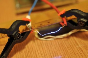
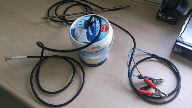
Here is an electric fence perimeter protection circuit designed to run on batteries and provide configurable pulses of up to 20KV, to protect a tent perimeter against bears or other animals, out in the wild. It doesn’t kill as the output current is limited, but it is definitely not for those with medical (heart) problems. So be advised to use extra care and awareness when constructing or deploying such a device.

As said, the high voltage generated is not dangerous because of the low current (and power), but it will produce intense pain. Similar circuits are being employed for pastures, and I’ve seen many in the mountains, in several countries I traveled to.
The circuit:

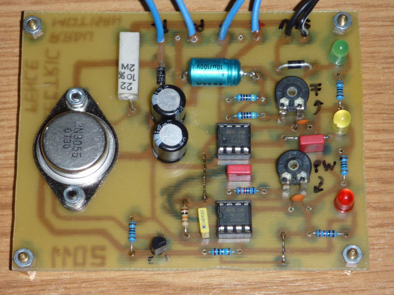
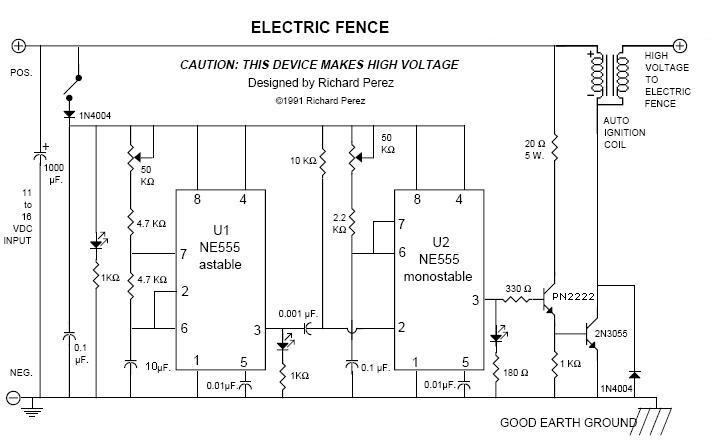
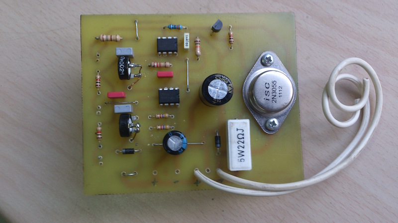
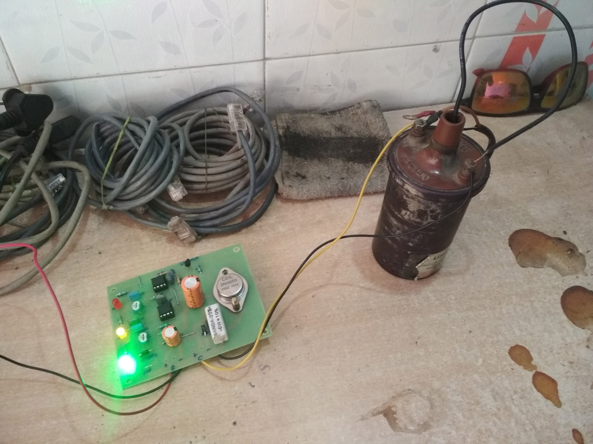
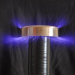
The device uses two 555 timer circuits to generated a variable frequency, variable width pulses, that are used to drive an auto induction coil. For my design I’ve used a VW Bosch induction coil with excellent results. The power is provided by 8 AA 1.5V batteries, connected in series for 12V. The frequency and the pulse width can be adjusted using two potentiometers. The frequency specifies how often will the high voltage pulses be generated and so fed into the perimeter wire, while the pulse width influences the amount of energy fed into the coil, and so how much high voltage energy will be sent into the wire (more energy, more painful the discharge will be).
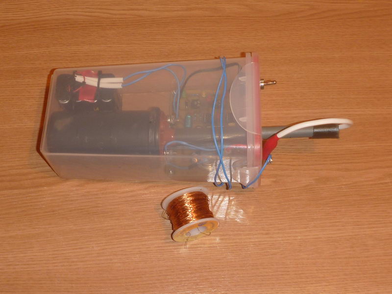
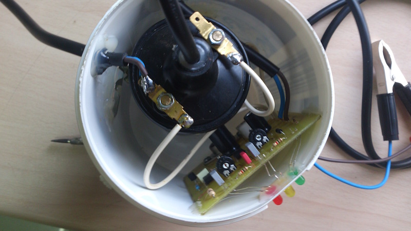
The circuit , the batteries and the induction coil are enclosed in a waterproof plastic recipient. The high voltage output should be connected to a loop of metallic wire placed around the protected perimeter. This high voltage line should be insulated from ground (use some plastic for that). The cold output should be connected to a good ground: insert a 50cm steel pipe or wire into the ground. Rocky soils or dry soils need a better ground (use a longer wire and bury it as deep as possible).
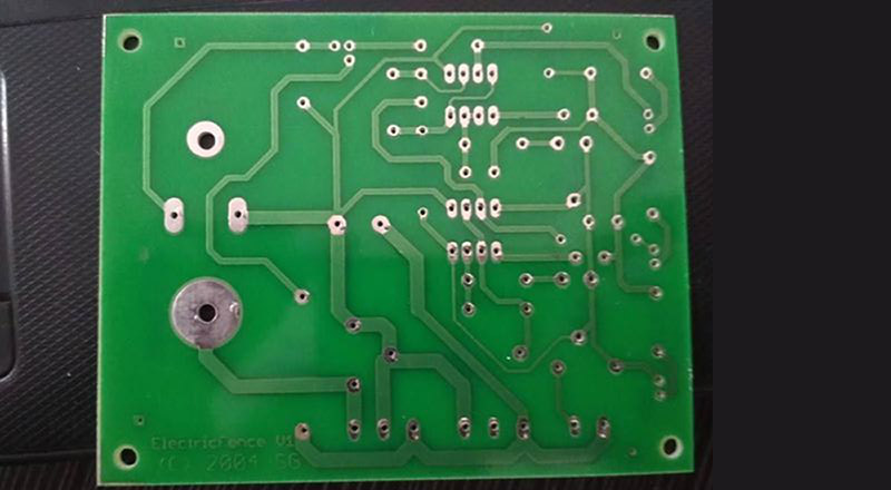
Circuit diagram:
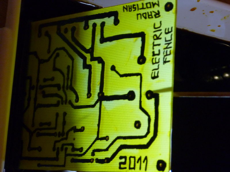
The PCB layout can be downloaded here: ElectricFenceVer1.0
Note: This will not work well with a flyback transformer used instead of the induction coil. A good quality induction coil is a must for this device to work as expected. If testing the output, make sure you set the device to minimum power, by adjusting the pulse width. The shocks at higher power are painful!
Test video:
The PCB Layout in PDF: ElectricFenceV1
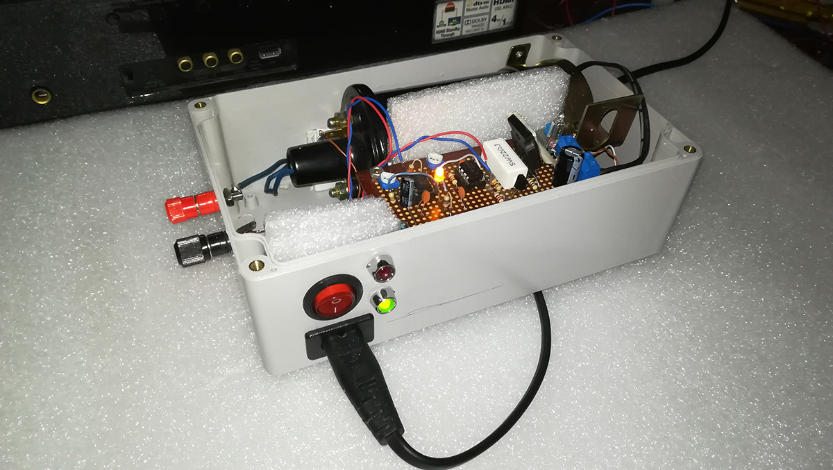
Variants built by my readers:
Update Nov 25, 2014: Noe Lourenço Agostinho Nézocas mailed me a few pictures and even a video of his own construction of this electric fence. You can see them here.
Nice work Nezocas!
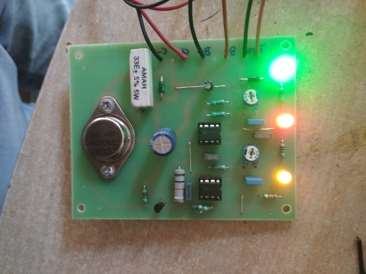
Update Feb 10, 2019: A few years later and this circuit is still very popular! Kalpesh Desai built professional PCBs for it. Nice work Kalpesh!
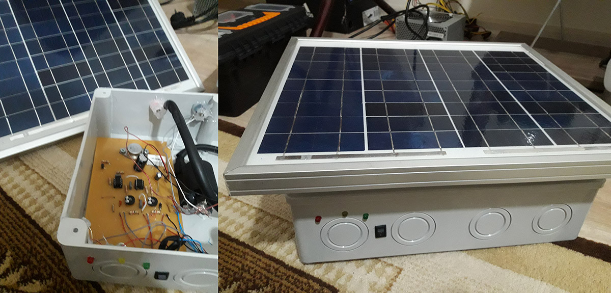
Salih, from Turkey, pushed things even further, with the addition of a solar panel to allow this electric fence energiser to operate autonomously in remote locations. This is the best build so far, congrats Salih!
Update April 11, 2019: here’s another high quality build by Kalpesh Desai from India:
This is yet another example of high skill resulting in a beautiful construction. Congrats Kalpesh!
Update May 11, 2019: Tharindu De Silva built the circuit on a breadboard, and enclosed it in a rugged plastic box to use it against rats. It looks great, nice work Tharindu!
Design Updates
For those interested in building an Electric Fence, please note that there is an update version of this circuit, presented here.
Pingback: Variable duration, frequency and amplitude Pulse generator « PocketMagic
I wish you could listed down all the parts used so I could build myself one.
thanks
@victor, please see Circuit diagram . All the components are listed there.
Thanks Radu. I overlooked that.
Hi Tks for This, How many Kilometers can fence this one?
how do YOU open the file for the PC layout? Its in Zip file. I cant open up the file. HELP!!!
THANKS
You will need Eagle software to open it
Radu,
isn’t there any other way? could you make the file into Abobe PDF? So it would still be alot easier?
thank you
Radu,
Please transfer the file into Adobe PDF? thanks
Victor, see it here: http://www.pocketmagic.net/wp-content/uploads/2011/09/ElectricFenceV1.pdf
Hi Radu!!!
thank you very much for the link!!! Fantastic!!! I was able to get the PCB diagram. One question though, this PCB diagram as you face it is the under part of the (copper side) of the board?? Right? Also would you have any suggestion as how I could efficiently print or transfer this diagram to the copper side of the PCB without losing detail? Im just a beginner in electronics this would be my second major project. I was able to build me a variable voltage regulator (dc) in the past. Now Im excited in creating your idea. Again thank you very much.
Hi Victor,
Yes, this is the mirrored version, showing exactly what you need to print on the copper side.
Easiest way is to print it on paper, put it over your copper board and drill the holes.
Then remove the paper and while keeping an eye on it, draw the connections between holes, using some resistant paint or lacquer and a sharp brush or any other tool you’re comfortable with.
Use FeCl3 to corrode the rest of the copper, and you’re done.
Radu,
what is the exact size (in inches) of the pcb? thanks
can I get the electric fencer v1 in pdf layout with
only conneting lines for laser printing on photo paper
and then iron on to copper board.
Ai incercat pe gardul propriuzis?
L-am dus cu mine la munte dar nu l-am instalat. Cand l-am realizat, din greseala am atins iesirea, dar era pe setare minima, si a fost dureros.
Setare minima inseamna undeva pe la 1KV. Setarea maxima permite 20KV. Durata pulsului nu mai stiu cum era setata, dar “all-in-one” produce destul de multa durere.
Vara trecuta am fost in elvetia si am atins din greseala un gard de vite, am sarit ca ars. Culmea, pulsul a venit numai la vreo 3 secunde dupa ce am atins firul, are deci o frecventa foarte mica ce foloseau ei acolo. Ca durere produsa a fost cu putin mai mult decat ce am simtit la al meu pe setare minima.
Daca impedanta nu e corespunzatoare ,tensiunea e prea mica in gard .
Sant verificatoare pt gard – un voltmertu in trepte.
https://picasaweb.google.com/112827018205146693954/ElectricFenceVer10?authkey=Gv1sRgCM_TqMLHq8TF9AE#5713536625245616866
mi-am confectionat si eu o “sonda” de inalta tensiune, dar la ce gard mi-a trebuit mie, cat sa inconjur un cort, nu imi fac probleme pentru modificari prea mari in tensiune.
La noi sant probleme legale privind utilizarea ef.
i will also would like to know How many Kilometers can fence this one do
Hello i have the same question with scott how many meters can fence?Also is the maximum diameter of the wire that can take?thanks a lot
You’ll need to take into account wire resistance for distance voltage attenuation, and pillar insulators. At 20KV I expect these to be negligible, so you can use it for a few km easily.
can`t find 1N222A Transistor please tell other equalent transistor.
any generic npn transistor will do.
Dear Radu, can you tell me the specific type of the induction coil?, please. If not, can you write all the specs about that you used.
Thank you!
It’s a normal auto induction coil, mine was a bosch, taken out from a VW car.
Don’t you mean 1N2222A not 1N222A
2N sorry
Thanks Jak, yes it is a 2n2222, you can use any other generic NPN trnasistor.
Hi, Nice Circuit, What happens when the HV Output is shortcircuit, like grass or weeds or direct short.
Not good … the voltage decreases to a value that is not usable .
-In cazul unui scurtcircuit cind rezistenta tinde spre 0 ohmi (sarma,direct short),daca e mentinut se termina bateriile ;
-In cazul ierbii/alte plante (like grass or weeds )efectele gardului se manifesta asupra acestora ,nu asupra animalelor.
Hi Radu
I built this circuit, to use to energise a fence to protect some beehives. Unfortunately it is not functioning properly. There appears to be no pulse action at all, no matter what the position of the pots. When switching the board off, I get a spark, approx 5-7 mm. The main power transistor gets very hot if the power is left on. So I am not sure if there is an obvious explanation. I was very careful in wiring it up, but perhaps something is wrong. I tested all resistors with a meter as I installed them, so I know they are all correct. There is no specification given for some of the components, even in Perez’s original article in Home Power.(I got mine from Digi-Key). So this is a bit of an unknown, although I believe what I have should be fine. I guess I have to start over. It took me quite a while to assemble.
Rob
Hi Rob, there must be some errors in your circuit. You can also post a few pictures so I can have a look:
The transistor should stay cool, unless you’re using some very high frequency (this is just a guess). Can you measure the oscillator frequency? Do you have a frequency meter, or a scope to show the signal on transistor’s base?
What components have no specs? I built two such boards without any issues, one is here, the other one can be see at: http://www.pocketmagic.net/?p=2343
so let’s see how to fix this.
what is the specification of the battery is it 1.5V/8AA. plz reply me as early as possible. I am working on this project.
I am working on this project and I am not getting the sparks. Do I need VW Bosch coil only? 8AA 1.5V does this type of batteries are available in the market? Please give me the details about the batteries as early as possible.
Is ignition coil and induction coil one and the same thing. Please reply me ad early as possible. I will be very thank full of you
@Sneha: normal alkaline AA 1.5V battery.
Check the oscillator and see if it is working.
The ignition coil used in auto is an induction coil.
I have bought a two wheeler ignition coil, but its not working, oscillator is working only problem is the sparks. If i get the same induction coil as you have used then it will work? And you have used box type capacitor, but i have used ceramic ones will they effect the circuit?
Can you suggest me a mini digital project with all the details?
I am working on this project and I am not getting the sparks. Can you suggest me more details of your project
you’ll need to check your circuit again, but also the ignition coil. feel free to post pics with what you did so far.
hi friend, great job!
can you please tell me how many volts is C1 cap 1000 uF/??? volts?
I am making this great project
25V or more
What application(s) are required to open your files on a Mac?
Hi, i’ve done this circuit and i got the pulse. but the output voltage does not reach up to kV. it only can go up to 300V. i’ve used hitachi ignition coil to step up the voltage. does ignition coil’s brand influence the value of output voltage? i need to achieve kV voltage for output in order to get a good result for my final year project. Please reply as soon as possible. thank you.
Hello Ain, you might want to try a different coil as well. This is a very simple circuit, and little can go wrong about it.
I wish you could listed down all the parts used so I could build myself one.
thanks
all the parts are listed in the circuit diagram. easy to build, nothing fancy.
Hello, is this circuit power input can connect to the 12V car battery?
Can i use the flyback transformer for the TV instead of the induction cail?
@ngks: yes you can use a 12V car battery
the flyback transformer produces high voltage but low current, you would need to rectify it and place a capacitor in parallel on the output, to get a shock . something similar can be seen here: http://www.pocketmagic.net/2011/09/battery-powered-high-voltage-multiplier-for-gas-igniter-or-stun-gun/
Hi Radu,
I built your 20kv electric fence circuit which works very well except – – every two or three minutes, the 2nd 555 (U2) goes u/s. Now I did use a Mosfet in place of the 2N3056, driven directly from the 555 via a 330 OHM resistor, i.e. did not use a PN2222 in between the 555 and Mosfet. Would this be the most likely cause of the constant failure of the 2nd 555 I.C. ?
@gary, You might be getting some high voltage spikes back to your driver circuit. This can happen with some types of induction coils . Try putting a small snubber, across the coil’s primary : a small neon bulb and see if that helps.
You need to use the PN2222 as well, for better results: it is used to properly amplify the trigger signal for the high power transistor (or mosfet in your case).
Many thanks Radu, will incorporate both of your suggestions.
sir can you tell ignition coil of generator or motorbike can also be used in place of ignition coil of car.is voltages effected?
@umair: yes you can use other ignition coils
greetings radu’
i plan to build the circuit soonest.how can i incorporate a relay circuit for alarm or sounder if someone touch the high voltage side.
@jhunflex you should be able to detect a voltage drop in the high voltage line
Thank’s radu..I’ll go to your suggestion very helpful to me.
Hi, Please do not be tempted to convert this circuit to run from mains, from a DC adapter or battery charger. There was a fatal accident recently here when someone did this. The issue is that fences attract lightning, this breaks down the insulation in the adapter and 230Vac can then make its way back onto the fence. This is why fence safety standards like IEC60335.2.76 require 25kV isolation on the output transformer.
Regards
Paul
Hi Radu,
I have urgent need of your device as there is a threat from bears!
Ιt’s possible to buy this device?
(please for you email and don’t show this message if not must)
Regards
Nikos
pls, kindly mail a list of the component needed because i’m lost here the circuit diagram and image diagram and video have me confused
Pingback: Pulse generator (Variable duration, frequency and amplitude) « PocketMagic
Hi Radu, good day can you give me the voltage of all capacitors in the circuit? then the wattage of all risistors, then the rectangular white one.. thanks… hoping for your reply.
For caps use 25V or more. The resistors are 0.5W, unless otherwise specified.
Thanks Radu, i’l do the cuircuit asap..
Ok Ronnie, drop me a few pics when done, I’d like to see it.
Is there anything I can do to stop transistors from heating up
@Jack: I didn’t experience any extreme heating
Hej Radu whats the max input current from the batteries? 1 Amp when in series?
Matej, this circuit uses less than 100mA at 12V.
Aha so it will work with a dc 12v charger with no problems:)
yes.
Hej radu. I have made made the circuit and it works very good. I use a car coil 1:15 and on the end it gives a good shock to the electric fence, but if i at a little more power what shoud i do change the resistors to smaller values or use more voltage(now iam using 11V) . thaks
Hi Radu. I’ve tried ur board using 1000uf 16v & 4.7uf 16v capasitor, it works well. But when i tried using 25v capacitor, the 22ohm resistor get burn. Is it ok if im using 16v capacitor and what’s the different if using 25v capacitor?
HI. you probably need a resistor rated for higher power so it will not burn.
What’s the different if i use 16V capacitor?
Hej Radu can u tell me how many Joules in power canproduce this circuit and if you know the pulse duration
i think the formula for joules is V*I*t(mili second). My board has 11.84V/about 800mA at the most fet transistor and i dont know the pulse time??
@Hafiz: you can use a 16V cap
@Matej: I don’t have the board at hand right now, so I’ll try to answer your questions later.
ok Radu:P
2n3055 not a good choice, more better is TV horizontal tranzistor.
@tehniiik: yes, you are right
I Radu
Thanks for the idea.
I am trying to built the electric fence to proteck my bees against the asia hornets.
I bought all the components and I’ve connected on a trial card.
Maybe ther is a mistake in your list : You wrote a 4,7uF in your list but you never use it on the circuit. Could you please confirm that this 4,7uF is used beetween 6 of U1 and groud ?
Thanks for your help.
For the moment my electric fence doesn’t word. I’ll check it again and I inform you of my progress.
Mr.RADU..thanks for this CIRCUIT…is there is way to add ALARM TO THIS….if so pl give details…REGARDS udai
Hi Radu,
You know how to measure output 20KV ?. Probes are way to expensive. Can one build one with resistors ?.(on DMM)
In the old day’s they had a probe for measuring HV in a TV (color Tv up to 30 KV).
Thanks,
Hi Frans,
You only need to build a voltage RC divider probe. Here is a simpler resistive divider probe for high voltage measurements: http://www.pocketmagic.net/2010/11/homemadediy-high-voltage-probe/
Is it works ?
Radu can you tell me the names of all the elements that are used. to make them more easily found by the Eagle. Thank’s
@ZyKON please use the circuit diagram to see the components.
hi radu,
just want to ask, why your schematic is not tally with PCB drawing board, example is, there were 4.7uF is using in the list but on schematic it doesn’t exist, do you mine to help me on this… tq
@mazlan, what 4.7uF cap?
Hi radu, yes its capasitor 4.7uF. If you go through the pcb there was a capasitor 4.7uF. And if you count the components in your picture its less 1 component compare with your schematic
cit costa sa-mi faci un generator deimpulsuri cu bobina
am cumparat un generator de impulsuri de la cluj in o luna s-a dus l-am trimis la garantie si nu mai raspunde nimeni la telefon.Am cam 2km de gard.
nu le prea am cu forumu scuze pentru greseli
Salut. Ai putea sa-mi construiesti unul ca cel din poza ? Suport toate cheltuielile. Rog reply.
hi radu,
hi its me again, can you help me on this, seems the schematic is different with your complete circuit. Can you give your email so i will give details about my confusing. thanks
@ioan; cred ca da, cam peste o sapt
@mazlan: the components are not critical, except the caps and resistors connected directly to the 555s
thanks radu, ill try to proceed, see how it goes
Hi Radu, thank you so much for this electric fence… however I think I did something wrong, I went to the electronic part store and they gave me everything from the eagles software partlist… I will show you on the pics what I did. When I plug it in to the wall and turn on the switch back on… The D1 Diode overheats and not even the LEDs are working… I am wondering if I need to plug in the ignition coil as well to make it work…
Anyways as you can see… they gave me ceramic capacitors instead of the box ones, some 102, 103 and 104 I guess… Also… the only resistors that are different from the part list are: R7 180 but they gave me a 150 instead, and R8 330 they gave me a 330k instead… not sure if that makes any difference lol… did I messed up? Thanks for your help, I appreciate it.
Pic available here:
s290.photobucket.com/user/jcxperts/library/Projects
Hi Carlos, your board looks great!
However changing the components values with a few orders of magnitude (330 -> 330K) WILL result in failure.
Regarding the type of capacitors it is ok, as long as you keep to the given values.
Hope your next try will be successful.
Hi Radu… Wondering if we can add an alarm to this… Thanks in advance!
I found this… DC High Voltaje Drop Detector
http://electronicdesign.com/power/circuit-combines-dc-high-voltage-drop-detector-undervoltage-alarm
@Carlos: yes, that looks very good.
salutare Radu ! ai putea sa imi faci si mie un montaj ?
Salutare tuturor!Am realizat si eu schema din imagine,dar incercandu-l la fata locului pe niste sarmane capre nu mi s-a parut a le deranja foarte tare,se vedea ca le curenteaza dar ma asteptam ca la atingerea firului sa, sara inapoi dar aproape ca dansa printre fire. Cam cati joule scoate schema respectiva si cum as putea sa fac acel soc un pic mai dureros? Ms pentru ajutor!
Salut Dumi,
Probabil circuitul e reglat pe putere mica si caprele sunt protejate de par. Inainte de a incerca pe animale, ar trebui sa vezi ce scanteie obtii intre electrozi, imediat la iesirea din bobina de inductie si sa te familiarizezi cu reglajele:
Scanteia trebuie sa fie cat mai lunga si cat mai groasa / grasa / zgomotoasa.
Daca te uiti la filmul asta: http://www.youtube.com/watch?v=EQhK8B1UPIQ o sa vezi la ce ma refer prin grosimea scanteii. Toate aceste detalii se regleaza prin cele doua potentiometre.
Daca scanteia ta e prea mica, nu va afecta caprele pentru ca nu va trece de par.
De asemenea trebuie sa te asiguri ca bobina e buna, nu e strapunsa in interior, din nou testul de mai sus va prezenta si asta.
In rest nu ma pot gandi decat la o baterie descarcata, sau de amperaj prea mic, dar nu cred ca e cazul. Totusi, verifica-le pe toate sa fim siguri.
Ca si o curiozitate, uite si alte surse de inalta tensiune la care am lucrat: http://www.pocketmagic.net/2009/07/high-voltage-power-supplies/
Ms mult pt sfaturi,cum am zis schema functioneaza foarte bine si are o scanteie cat se poate de sanatoaza,nici mie nu mia venit sa cred inainte de a ma apuca de schema. Poate a fost greseala mea ca am intins firul pe un tarus din lemn si auzeam cum se descarca in lemn,sa fie o pierdere mare din cauza asta? erau doar 3 tarusi si 20 m de sarma(de fier si galvanizata!?)nush ce sa zic, dar pana la urma uitanduma azi pe youtube am vazut si altele care nu pareau sa curenteze mai tare, Prima data lam incercat pe un ciobanesc german si 20 de minute nu a mai iesit din cusca, probabil ca la capre le place:D.
Imi cer scuze dac pun prea multe intrebari dar condensatorul de 0,001 micro ce face legatura intre pinul 3 si pinul 2 al celor doua integrate are un mare rol acolo,deoarece mie nu mi-a functionat correct cu el in schema,chiar si simuland schema intr-un program aveam aceiasi problema, acuma functioneaza fara el.
Condensatorul mentionat are rol de cuplare capacitiva dar semnalul e ok si fara el.
legarea firului pe stalpi de lemn NU E OK, cu atat mai mult cu cat s-a auzit descarcare prin acel punct.
Aceste descarcari carbonizeaza lemnul si isi formeaza un canal de conductie care nu va mai lasa energie pe fir.
Deci mare atentie, se lucreaza cu izolatori ceramici , de sticla sau in cel mai rau caz plastic (PVC).
probabil dupa ce vei corecta problema, caprele vor fi mai atente la perimetrul gardului. Un test care te sfatuiesc sa-l faci e sa tragi un fir de la borna minus a bobinei si sa-l apropii de linia de inalta tensiune a gardului, asa cum e montat, si sa confirmi prezenta unei scantei de lungime mare. Daca nu apare scanteia, sunt pierderi si trebuiesc verificati suportii. Dar oricum, lemnul pot sa-ti spun din start ca trebuie schimbat. Succes!
ps: mi-ar placea sa vad cateva poze, cu caprele si gardul electric. Imi plac amandoua si sunt desigur curios. Asta daca ti-e cu putinta. mersi!
Dupa ce ai zis acuma sunt sigur ca aia a fost problema, deoarece am facut testul zis de tine si dac puneam direct aparatul la borna minus fara a fi conectat la sarma aparea o scanteie foarte sanatoasa dar dupa ce am conectat sarma nu mai era chia asea,de fapt cu mult mai slaba. Ms pt sfat,cred ca o sa cumpar izolatori din magazin si o sa vad pe urma,ma gandesc ca lungimea firului poate fi fara probleme undeva la 500 de metri!? sau nu? Daca folosesc sarma precizata anterior este vreo problema,mai buna aia din magazine? O sa pun si poze cu siguranta, dupa ce o sa fie totul facut cum trebuie,eventual o sa fac si un video, doar sa primesc o adresa de mail sau ceva ca aici nu stiu cum se procedeaza:D, daca nu vrei sa iti apara aici iti dau pe al meu: iancu_valentin22@yahoo.com, faci un semn si cand o sa am materialul o sa iti trimit cu siguranta.
Firul e bun cam de orice fel, la asa tensiune inalta pierderile sunt infime. Din acelasi motiv distanta poate fi teoretic si de cativa kilometri. Dar eu nu am incercat. M-as bucura mult de poze/film, orice, sunt chiar curios cu arata montat “pe teren”, cu atat mai mult cu cat sunt si capre in peisaj . Adresa mea de mail te rog sa o gasesti la sectiunea about, din meniul de sus.
Ok,am gasit,cu prima ocazie o sa primesti,eu zic ca in maxim doua saptamani o sa reusesc sa instalez totul. Pana atunci o sa mai fac un dispozitiv,aceiasi schema dar am refacut cablajul pentru a fi mai compact si sa incapa mai usor in carcasa folosita de mine. Ms mult pt safaturi,spor la construit si multa grija cu tensiunile astea.
Cu care tensiuni sa am grija, cu astea: http://www.pocketmagic.net/2011/03/high-voltage-power-supply-140kv/ sau cu astea: http://www.pocketmagic.net/2011/10/twin-marx-generator/ ?
Glumesc, n-am mai avut de mult timp de ele, dupa cum se vede si pe data posturilor .
Cu al doilea generator de pulsuri de inalta tensiune pentru gard electric pe care vrei sa il faci, te sfatuiesc sa astepti cateva zile sa apuc sa pun varianta noua pe care am proiectat-o.
Hmmm,foarte frumos,dar bine zici, timpul! Si mie mi-ar placea doar ca sunt abia la inceput de drum si timpul ma cam costa:D asea de cate o lucrare mai simpla ca electric fence, sau cateva automatizari in rest…ramanem cu proiectele doar in minte.O sa astept si varianta noua de care ziceai,dar e buna si asta.
Radu,
Thank you for posting this. I made a pcb yesterday and built it up today. Works like a charm. I get a nice 3/4″ long spark, and I know it will work well for my garden.
Thank you,
ken
Glad to hear that, Ken!
Hey Radu,
I want to use it to build a perimeter around my paddy fields to protect it from elephants. I want to know whether this would be enough to fit my purpose and also in the image you have used a 100uF capacitor for C3 but in the schematics it says 4.7uF. Can you specifically tell me which is the correct one to use.
Please reply as soon as possible because it is very urgent. Thumbs up for this great idea. 🙂
Thank you,
Ashnuka
Dear Ashnuka,
I have little knowledge on how thick is the elephant skin, but 20KV should probably be enough to induce pain to them as well.
I don’t know what part are you referring to by C3. Please clarify. The filter caps are not crucial, so besides the resistors/caps attached directly to the 555s, you can use what you have.
Dear Radu,
I am asking about the axial capacitor you have used, The blue one in the image. In the diagram it says its 4.7uF while the image its clear that its printed 100uF.
Also i want to know whether i can run this system off a 12v 135Ah battery directly and if i needed any additional items to be added.
Please try to help me out
regards
Ashnuka
How we can see the thicknesses of the lines connecting the components together?
Salutare,am realizat si eu montajul acesta si cand l-am alimentat led-ul rosu nu se aprinde si nu am scanteie.Se aprinde doar cel verde si cel galben.Bobina e buna(probata),bateria incarcata.. ce ar trebui sa verific?Ceva sugestii mi-ar fi de ajutor.Va multumesc.
@Ashnuka, please refer to my previous reply to you. Regarding the battery, yes you can use a 12V 135Ah battery.
@vangelis: there’s a PCB layout image attached above.
@Eduard: salut! Un osciloscop ar raspunde repede la intrebabi. Pot sugera verificarea polaritatii conexiunilor la bobina, trebuiesc respectate cele din schema. Ar mai fi partea de circuit dintre cele doua 555-uri, probabil acolo e problema, semnalul nu ajunge la al doilea 555.
There are some Bosch induction coils having a 3-4 ohms resistance in the primary, and others that are under the ohm. I used one of these and I burned the power trasistor. You need to put an external reistor?
What will be the frequency adjustment for both IC? What will be the best setting? I have assembled the circuit, both LED blinking, first one fast and second one slow blinking. Kindly advise.
Salut, revin cu o intrebare. Ziceai undeva mai sus ca se poate regla tensiunea intre 1 si 20kv, asta cum se face mai exact? Eu ce observ, la mine, ca din cele doua potentiometre pot sa reglez durata impulsului(cat de dureros sa fie) si frecventa impulsului, nu imi dau seama cum se regleaza tensiunea. Apropo, nu am uitat de video si pozele promise dar a venit iarna, animalele au ramas libere si momentan nu am la ce sa folosesc gardul electric, astept primavera 😀
Salut, acea “durata a impulsului” controleaza si voltajul maxim pe care il scoate bobina. Se poate verifica usor, prin lungimea maxima a scanteii in aer.
i want pcb layout with only mirror image..not consists any component fig.
just mirror layout..
Ahaaa…,am intales, dar cum as putea sa adaptez cel mai simplu sa functioneze si la 220, ce sursa ar trebuii, eu am incercat la o sursa de laborator si nu functioneaza, numai cu rezistente nu se poate, adica fara traf? Multumesc pentru raspunsuri!
Salut Dumi,
Poti folosi un trasnformator de 12V curent continuu. Amprajul nu trebuie sa fie mare, 12V @1Amp e suficient.
Salut.am o intrebare: cum se poate sa introducem (daca se poate) si un Phototranzistor or Photodiod ca sa sistemul finctioneze numai seara( noapte).
what is the rating for the ignition coil?
Hello, Radu and thanks for posting this design. I built the circuit and the two timer stages are working perfectly, but the transistor output stages are not. The output (pin 3) of U2 cycles between 0.24V and 7.7V, but at the base of the 2N2222A, the voltage only cycles between 1.40V and 1.59V. Is that normal? Then at the base of the 2N3055, the change is even smaller; it goes from 0.846V to 0.892V. This is with no load on the circuit, that is, no automotive coil is connected. Do you have any suggestions for troubleshooting this circuit?
Thanks very much,
Will
hello. this is a excellent work. i’m interested im built this project. do you know how much batteries last? or the power consumption ? tnks
Salut, vreau sa mai fac un dispozitiv folosind aceasta schema (primul a functionat foarte bine dar cineva cu ,,mana lunga” m-a lasat fara), dar am ceva probleme cu 2n3055 mai exact din 10 bucati doar cu unu merge bine, cu restul obtin doar o scanteie anemica, tranzistorii sun noi si nu sunt arsi, in loc de pn2222 folosesc bc107 dar la primul dispozitiv am folosit acelasi si a fost k, am mai modificat si valorile rezistorilor de 1K,330 ohmi si 20 de ohmi, bobina de inductie noua,dar tot degeaba. Condensatorii din piciorusele 5 ale integratelor sunt obligatorii, dar in locul condensatorului de 1000uf se poate pune de valoare mai mica in caz ca nu avem? Multumesc!
Am masurat tensiunea la bornele unde vine conectata bobina si nu am numai 6,4V (cu bobina deconectata)
Care poate sa fie problema, am incercat si cu irf540, irf 510 in loc de 2n3055 si tot o scanteie anemica, daca pun in schimb bu208 otine o scanteie de 2cm poate chiar mai mare, care este diferenta intre acesti tranzistori? Multumesc!
pentru domnul DUMI, ce valori ati modificat la rezistente? eu am incercat si cu BU208A si cu 2N3055 si tot asa anemica e scanteia?si am facut 3 montaje, bobina folosita e de pe Dacia,una e romaneasca si una e Bosch.Multumesc
Buna lucian, cu Bu208 am lasat valorile din schema si a functionat destul de bine, valorile le-am modificat pentru ca am vrut neaparat sa functioneze cu 2n3055 ca si pana acuma dar nu a mai mers, in schimb daca puneti un condensator pe bobina s-ar putea sa aveti o surpriza placuta, dar si asea este o diferenta intre tranzistori chiar de acelasi fel.
Can we apply this to an 1000 meters long electric fence (wire)
Regards
@Lucian, Dumi am facut si eu cateva teste cu diversi tranzistori, si intr-adevar apar diferente. Voi incerca sa ma lamuresc complet inainte de a trage concluzii, iar cand le am, le voi impartasi aici.
@Nezocas: yes.
Buna, si eu am incercat cu mai multe tipuri de tranzistori, dar cu BU208A, si BU208D au mers cel mai bine, scanteie 2cm pana la 3 cm, problema insa este ca la acea scanteie de 2-3 cm eu am pus mana si nu curenteaza foarte tare, este suportabil, am schimbat condensatorul de 100n ce apartine integratului U2, am obtinut o scanteie mult mai dureroasa dar bateria se termina in cateva ore.
Oare nu se gaseste o schema a unui aparat profesional, poate facem o copie, alea din cate am auzit au o putere asea de mare ca arde firul de iarba care vin in contact cu gardul. Si inca ceva, am observat ca rezistorul de 20ohmi se incalzeste destul de tare, acolo nu se pierde prea multa putere. Am incercat si sa renunt la acel tranzistor si sa inlocuiesc toata partea finala cu un mosfet dar obtin o scanteie anemica, nu inteleg de ce!
Imi cer scuze ca pun atatea probleme dar am mai observat ceva ce nu pricep, daca bobina o conectez corect adica plus la plus minus la minus se fac descarcari necontrolate intre borna de inalta si bornele de alimentare fara insa sa pot izola, daca inversez polaritatile nu se mai intampla acest lucru.
Dear sir
this is sam from china, we offer fence wire and wire cable which can used in electric fence.
we saw your company from web, we are the biggest company to produce the metal wire or rope which used in the electronic fence.electric fence can also integrate with the CCTV,GSM and alarm panel. We are the chinese standard drafting unit of this kinds of wire. We offer this kind of products to so many local provider of security solutions and aslo export to many company. Our products details as below:
1.the wire or rope used in pulse electronic fence/Perimeter Security Electric Fencing, steel grade is Al alloy grade.
A:single-stranded size mostly in 1.6mm 1.8mm 2.0mm 2.5mm( of ocurse we can offer 1.1mm~6.0mm)
B:1*7 strand rope, size mostly in 1.5mm 1.8mm 2.0mm 2.2mm( of course other size as the buyer need)
2.high-voltage insulated wire,for the host and the electronic fence wire insulation parts, connecting and corner jumpers, pressure values 20KV, Al alloy wire core, and a consistent alloy wire material, avoid the electrochemical reaction.
3.the wire rope used in tension electronic fence, in stainless steel grade AISI 304 or 316
A: 1*7 strand size like 1.0mm 1.2mm 1.5mm 1.8mm 2.0mm
B:7*7 strand size like 1.0mm 1.2mm 1.5mm 1.8mm 2.0mm
4.other galvanized electric fence wires( high tensile carbon gla steel wire), size and tensile strength as the buyer need.
For more details welcome please check with us http://www.jinruimetals.com
thanks.
I built the circuit, and it worked fine–easy build. I connected the GND term to building ground, and grounded the case of the ignition coil too. When I turned up the pulse width, I heard a small snap from the coil every time the circuit fired. But when I touched a wire from the ground to the fence wire, I got one SNAP and then the circuit was dead. The middle (yellow) LED stays on, and the red one stays off. It appears that at least one of the 555’s was destroyed. Any ideas about what I might have done wrong?
Hi,
How can I send to you, some photos of my finished fence
Hello sir, I want to use transformer instead of ignition coil, so can you tell me the primary and secondary no. Of turns of transformer.please… I waiting for your reply. yours sincerely, Snehal Gawande
Buna ziua.As dori sa cumpar acest aparat, cine ma poate ajuta? Cumutumiri.A.T
@Paul: sorry, I have no idea what went wrong.
@Nezocas: Please see my email address under “About” section of this blog. Would love to see your build and include your pics in this article.
@snehal: You can use a 220V->6V small transformer, and connect the 6V secondary to this circuit, and collect the HV output from the 220V primary, BUT, those transformers are not built to withstand the high voltage, so it will fail easily.
@Tony: detaliile de constructie sunt toate prezentate mai sus, te-as putea ajuta si eu dar stau prost cu timpul liber. Poate cineva poate construi o placa pentru tine.
Thanks for a great circuit. I am building version 2 at the moment, but the wiring for the LEDs appears to be wired in reverse- is this the case?
Thanks
Alen
Sorry, but my previous post was not clear. In your circuit version 2 all your LEDs (Yellow, Green and Red) are shown in the circuit diagram the wrong way around. That is the anode is connected to ground rather than +12v.
Hello Radu!
The 2N3055 can by replaced with TIP3055?
Thank’s!
@Carlos Can you add the alarm to the fence?
Buna Radu !
Cum verific daca e bun montajul INAINTE sa leg si bobina .
hello radu are you sure this circuit really work?
I like fakes, on top when its funny. I spend money and time and off course nothing works . Some people have many time to spend to annoy others.
Pass this site and Go and buy a fence sold on the web.
@Turbinao you got the demo, you got the schematics and you got copies made by others. And you’re still talking nonsense. So you must be joking, or you’re just ignorant. Choose one.
Sir, Can you tell me what is the i/p and o/p of the transformer
like,
i/p —- voltage and current to the AUTO IGNITION COIL.
o/p —- voltage and current from the AUTO IGNITION COIL.
Thank you,
Waiting for the reply
You can take that blinking red light off and from that red led +ve and -ve point you can make alarm circuit
Hi Radu,
I am getting maximum 0.3V at the coil side. Is that normal or shoudl there be also 12V? What could’ve gone wrong? Please help.
Vally
good day sir
i build your circuit and it works fine for about 2 min and then it will not give spark . dont know if its my coil because also my spark is only about 5 mm .the coil is brand new .also the 2n3055 transistor gets very hot
please help
thanks
wikus
Can I purchase the PCB board .
I want to purchase this circuit, from where can I get? How much cost? Where to purchase? Pl send me information about this electric fence.
I’ve simulated the circuit in Proteus and it works fine, is there any chance to make the voltage variable at the output (example 1-12V) without losing the variable frequency and width pulses? A simple yes or no would do, if it’s possible could you point me in a direction, should I use a opamp, some kind of IC etc. Thanks
how much are the parts all together please?
Sir which type of capacitor use in this circuit. Electrolytic or non electrolytic.
And how much volts capacitor are there in the circuit.
Plz reply me as soon as possible….
Plz reply me sir….
hi there, i made this circuit, and works like charm. two months non stop.its very good. aleksandar from serbia
that’s great. Please post a few pics with your circuit!
hi Radu, i made this circuit, for my friend,everything working but resistor 20ohm 5w is heating, whats can be problem??
ESTOY INTERESADO EN OBTENER MAYOR, INFORMACION DE LAS TARJETAS PARA LA CONTURCCION DE EQUIPOS, A QUE DISTANCIA ALCANSARIA EN KM
Hello Radu
I made the circuit and it works fine at the beginning but then i have some problems with the second 555 it starts failing until it doesn´t work at all. i added a 4148 diode at the third pin of it trying to protect it and a neon bulb light between the coil but it keeps on burning the ic so what would you recommend me to do?
the semi conductor IRF840, what semi conductor is this?
hi, I assembled the circuit and I’m omly getting 2 volt on the coil output, should i get twelve or more?
You should get 20KV or more.
Hi again, now the power transistor got really hot and the coil too any idea What could be wrong? Thanks in advance
Hello radu, My circuit is not working. I use 2200uf-16volt capacitor and another type of induction coil. The ignition coil I use is like a transformer not the CAN type you use. Should I change the capacitor or the ignition coil? bcos the output is 16volt. Pls reply me. Thanks
the transistor makes a beep sound while turning the 50k pot
Fred, I don’t understand: the transistor makes a beep? How? Do the LEDS flicker like in my demo video? That indicates the switching signal is ok. Then check switching power transistor, then finally check your coil / transformer (it’s ok in different shapes as long is High Voltage rated) . For the latter simple use an ohmmeter on the primary and secondary windings. Will not show insulation breakdown problems, but will show continuity of the coils, and at least will get you started.
Hi radu, it flicks and led are working but the output is 16v
Hello Radu. I built a copy and it works fine i can send you a video or pics if you want but i feel that the spark isn´t strong enough so i would like to put a multiplier at the hv output to make it higher. What should be the values of the diodes and the capacitors to make it? Please reply me as soon as possible. Cheers.
Solved some issues and now I have both 555 working but the 2222a its not working. Nothing is getting to the power transistor and of course to the car coil
@Manuel, ok, please post a few pics / vids
@Alvaro can you check the signal on the 2222 base with a scope? Did you mount the transistor correctly? Is your coil ok?
Hi there ,
Any chance you would sell an item like that or build one like it for someone ?
Looking for one strictly for protecting my livestock from bears and wolves
Something along the lines of 110 volt or 230 volt , something that is going to last
The energizers on the market today in canada are sub par at best and do not
Deliver a jolt worthy of making them think twice about killing my animals .
if this is something you would be willing to help me out with ,thanks in advance
It’s on my list.
Hi Radu
i would like to use the energizer for a fence to protect my bee hives.
I want to ask you, with a perimeter of 700 meters and 9ohm/m resistance ,
so about 7 Kohm output load is there something i must change to the circuit or is it ok?
Thank you.
Seems ok to me.
Hi..you’r circuit conected electric fencr bundry.not working fence
*fence lanth 1.5km
HI . thanks for the circuit , that is an awesome work .but can u design a buzzer/alarm circuit for it , so that when ever output gets shorted buzzer/alarm indicates us.