
This is an update to my last SGTC project, presented here.
In just a few words, this is a SGTC, that takes a 10-20V input and uses a Royer oscillator to drive a half wave rectified flyback that charges a bank of capacitors that are discharged via a spark gap acting as a relaxation oscillator – to drive the primary of the tesla coil. Schematics in the original post. This article is an update, presenting a few improvements:
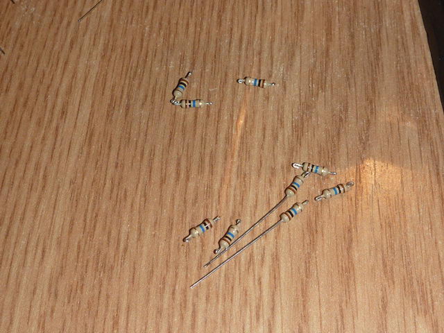
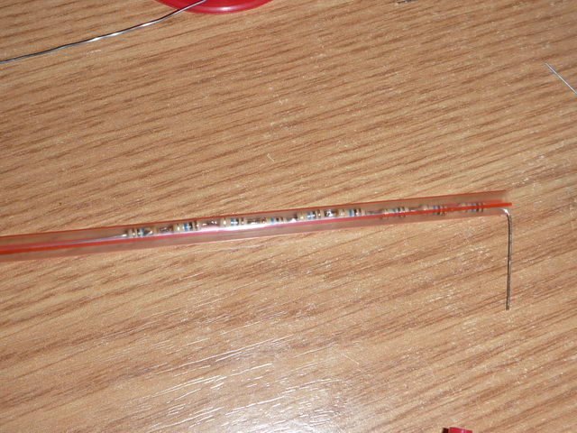
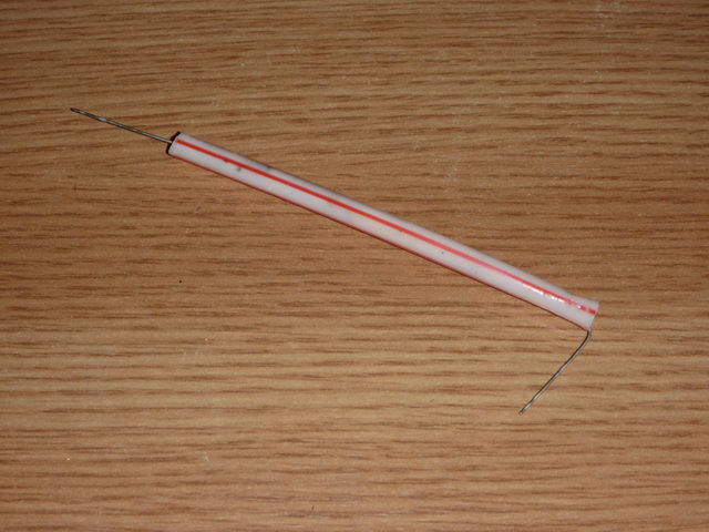
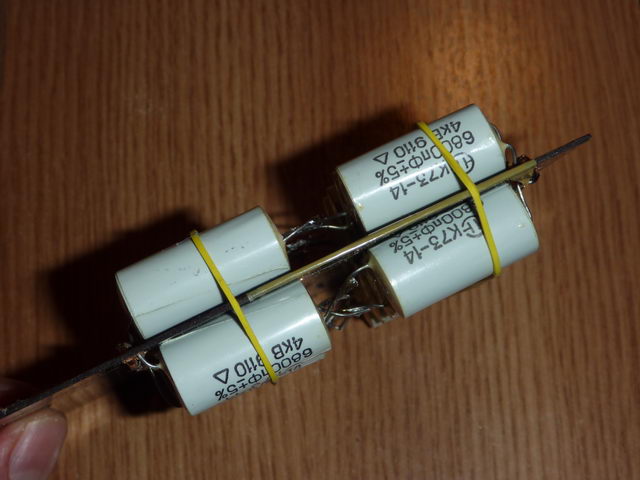
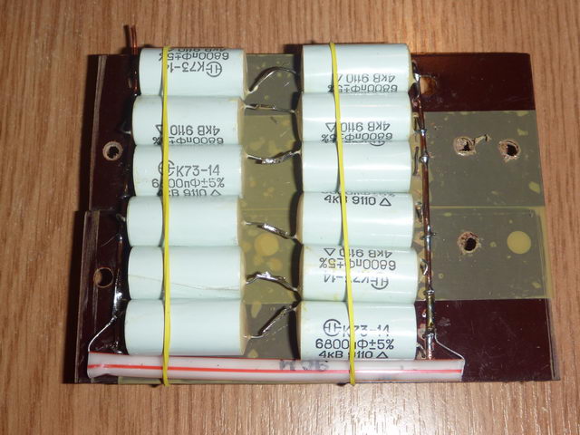
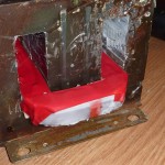
The capacitor bank
It has been upgraded and it now uses 24x 6800pF 4KV good quality Russian capacitors (Polyethyleneterephthalate foil), as found here. The capacitors are connected for 8KV 40.8nF on a Bakelite board. The entire setup is enclosed by a PET plastic foil. The capacitors use a bleeding resistor, made of 9x10MO 0.5W resistors connected in series. Here are some pics:

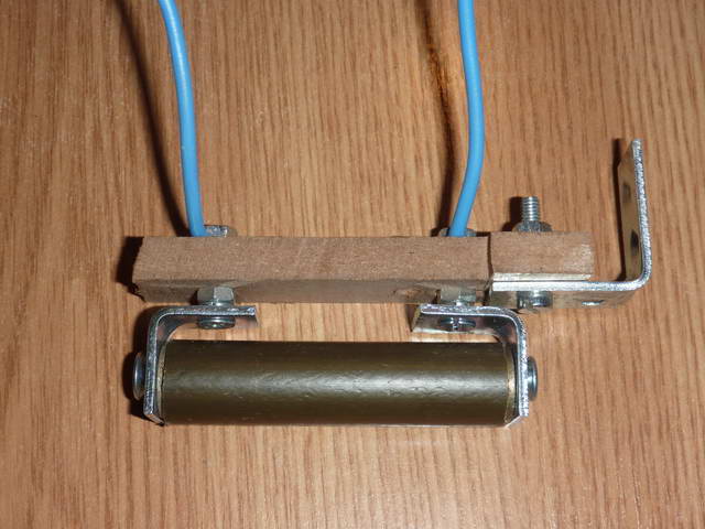
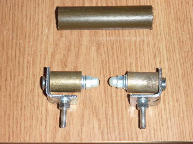
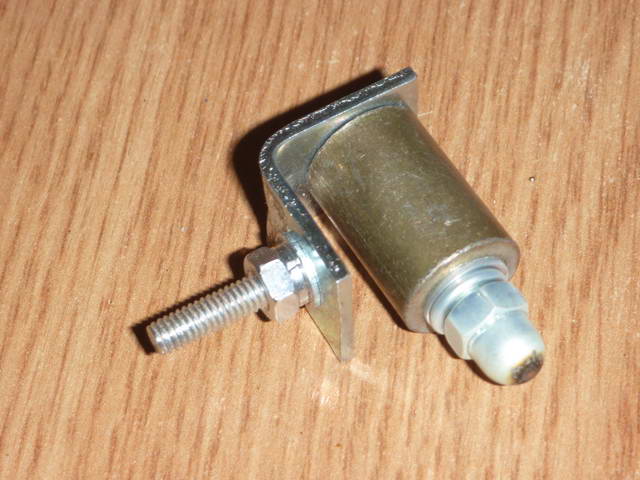
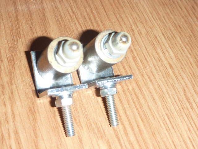
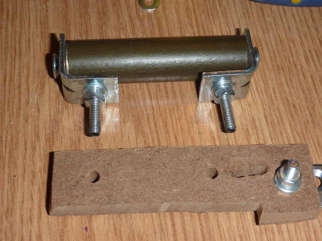
The spark gap
It now uses two sphere shaped screw bolts, inserted in a plastic pipe to reduce noise. As you know SGTCs can be very noisy, so this helps a bit. Ideally, I should have used a ceramic pipe, but I didn’t have one. Plastic can melt on continuous use, but I had no problems so far. The spark gap distance is adjustable via a screw:

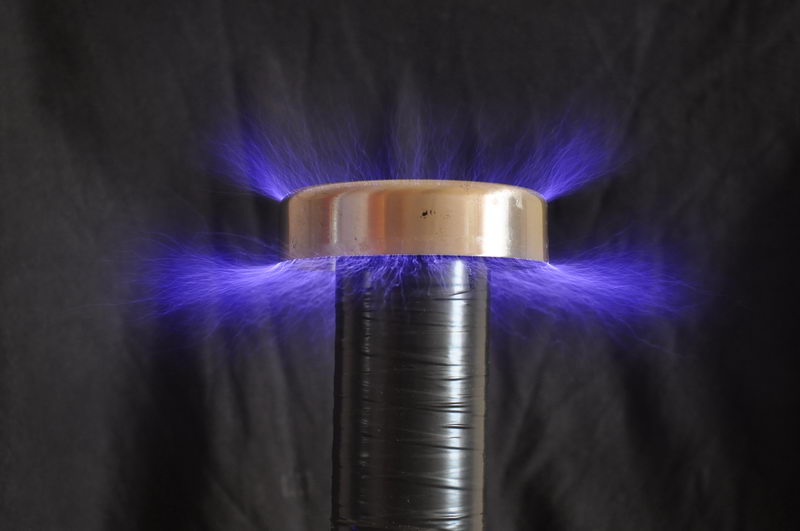
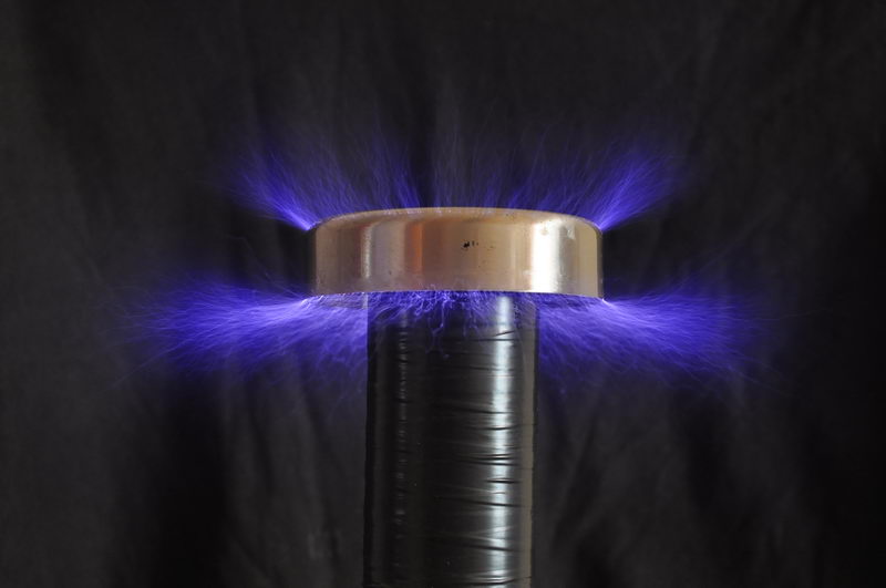
The result
Longer discharges! The supreme goal of a tesla coil! 🙂


I Have constructed [3] ZVS LOPT Drivers all of which Work reliably. The First [2] Using IRFP250 The 3rd Using Your Schematic. I have also Constructed a Small 250’000V [Approx]. Tesla Coil Using An MMC Array /and OBT Supply [6-7.5KV] This is not Perfect but produces nice Streamers….. I Decided After Building A UV-Laser using A LOPT and Plate Cap. That I Felt Curious About Building Your Tesla Coil Design 🙂 After Building It with Some Slight Differences in construction -The capacitors Being Slightly Bigger But With Less In a String ====/==== [=]40nf@8KV -on ignition and going for the longest arcs [drawing more power]? The caps Blow, a String of them ….I Change them Another String Blows[ My????????? Is My Output Voltage To Large For The MMC [The Caps Are The PETP Russian .01uf@4Kv X [16] Would Appreciate Your Input —By the way I Enjoyed building the Induction Heater It’s A Gem!
Dear Andy!
as you primary voltage is 7.5kv approx
you should have altleast double the voltage as you input voltage.
make tank cap that can handle approx 16kv
.
it will work fine. 🙂
faisal
xynosine@yahoo.com