Here is a list of high voltage power supplies with schematics and construction details, going from simple to complex. Be careful if building any of these, high voltage can be dangerous!
1. Simple flyback driver 10-15kV
Probably the very first high voltage device built by any enthusiast. It uses a power transistor (2n3055) and two coils: a primary and a feedback on a flyback ferrite core.
Schematics and details:

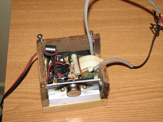
2. Push Pull (dual) 2n3055 flyback driver
You can use 2 x 2n3055 transistors in a better circuit that provides more power . However this too is prone to failure due to the transistor limitations.

A large heatsink is required as well.
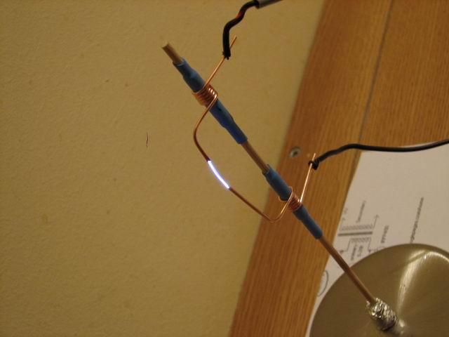
3. Voltage multipliers
If the flyback doesn’t provide the voltage you require, a solution is to build a voltage multiplier. You can hook it to any flyback secondaries that doesn’t have built-in rectification (diodes or multipliers).
A very easy to build design is the Villard cascade voltage multiplier:
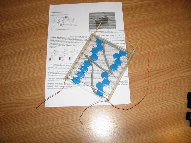
To understand how it works, you can read more on it here. I’ve built mine in a plastic CD box, this way I can add liquid wax for better insulation. Here are some interesting tests using the multiplier:
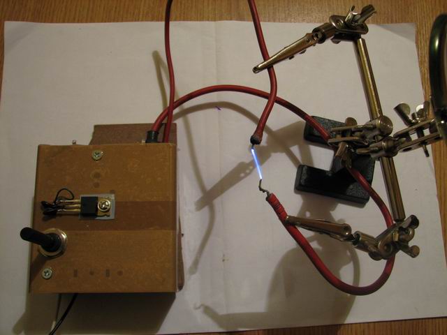
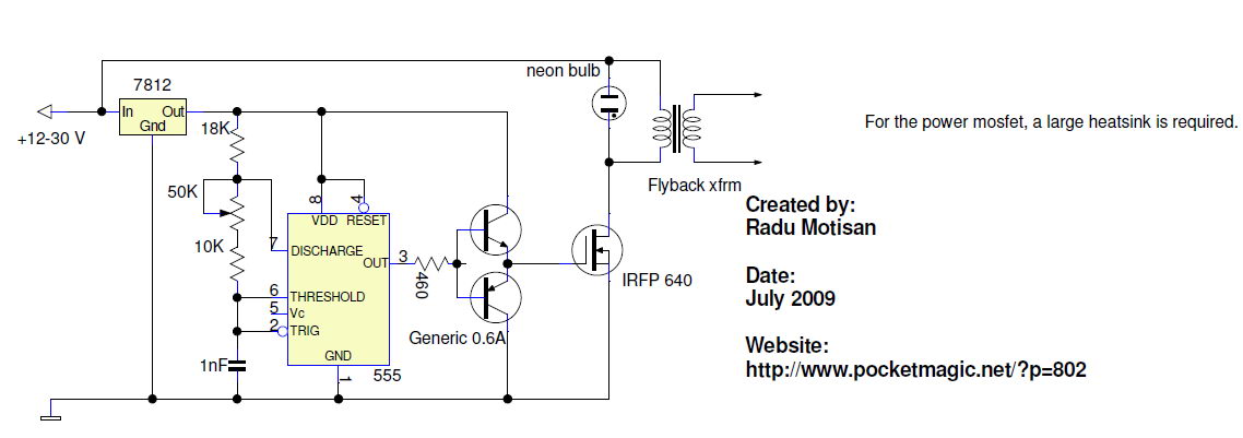
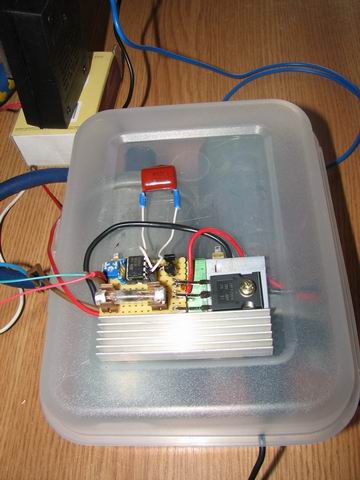
4. 555 Timer flyback driver
This circuit uses a 555 timer IC to pulse a power transistor with square wave at a frequency that is set by the capacitor and the potentiometers. It is a very efficient circuit, assuming the frequency is correctly adjusted.


Circuit diagram:
See it in action:
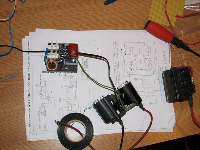
4. 555 Timer dual ignition coil 30KV
An even better approach for those that seek more power and higher voltages is using ignition coils from cars. I’ve got 2 from a scrapyard, and connected them in anti parallel:
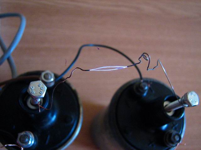
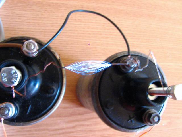

The driver used is the same as above (with a 555 timer), the difference is in using a different pot, resistors and capacitor for another frequency interval, and stronger mosfet, suitable for ignition coils:

Adjusting the frequency with the pot, I got some tick white arcs, similar to those produced by a flyback with a ZVS driver. A good indication of the power running in the system.
5. ZVS Flyback driver
A powerful driver with excellent results (no transistor heating, a lot of power pushed), is the ZVS (push/pull) driver, that was described in this article.
Here is the circuit diagram:

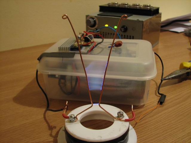
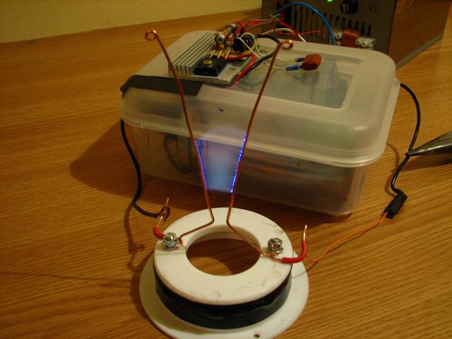
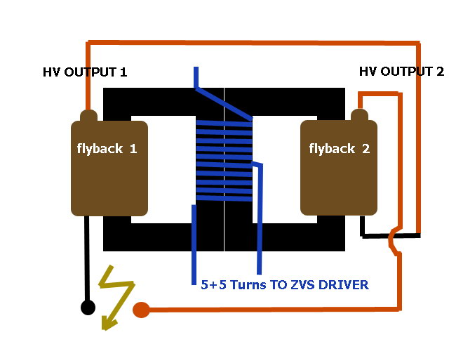
6. Dual Flyback driver
ZVS gives a lot of power, but the voltage is not great. You might want to put two flybacks in series, and use 2 separate ZVS drivers, or a single driver with the 5+5 primary coil wrapped around both ferrite cores:
7. Tesla Coil
The ultimate in high voltage records, this device was discussed here and here.
Taking advantage of the way the secondary is constructed, several issues are solved by construction: the secondary insulation is trivial.
High frequency Solid state tesla coil (HFSSTC):
More on the HFSSTC here.
To be continued. someday.
I have one zvs driver with pcb
That’s great Mhavskie, post some pics if you’d like.
Hello Radu!
First of all congratulation for your site!
I put two flybacks in series. I followed your schematic but the result with two flybacks was worse than a single one.
Any suggestion?
did you wired them correctly?
the hot wire from the first must be connected to the opposite wire on the second.
if this doesn’t work, try using two identical flybacks, or wire your own secondaries.
This the Link of my zvs driver
http://img121.imageshack.us/img121/4695/myzvsschem.jpg
http://img204.imageshack.us/img204/4852/zvsdriver1.jpg
http://img204.imageshack.us/img204/8092/zvsdriver2.jpg
http://img163.imageshack.us/img163/7618/zvsdriver3.jpg
Eu am reusit sa scot peste 100kv din doua transformatoare de Chevy la aproximativ 350W. Am folosit un 555 si mosfet sau igbt de putere. Problema e ca nu reusesc sa shuntez bine bobinele si se distrug tranzistoarele. Am incercat si neon da s-a topit in 5 secunde…Am un Fusor si pentru asta incerc sa fac tensiune cat mai mare…numai bine!
Hm, un Fusor, ar fi frumos de ai pune niste poze. Mi-ar placea sa-l vad.
La 100kv cred ca apar multe pericole datorita radiatiilor. Hm, cred ca ai o sursa de neutroni pe cinste.
Ce sunt transofrmatoarele Chevy?
Folosesc bobine de inductie (sunt detapt transformatoare nu autotrafo) de la Chevrolet Cavalier(sunt in philly, sua) legate in paralel la intrare si in serie la iesire. Folosesc mnosfeturi sau igbt-uri de putere ca switch , dar tot mi se prajesc pentru ca e prea mare tensiune autoindusa din primar. Trebuie sa fac un snubber mai bun…Fusorul (am sa fac niste poze…odata) n-a functionat niciodata cu deuteriu sau altceva decat cu aer,…e bun numai de bronzat la fata ca in felul acesta (grila externa, grila interna) n-o sa scoata energie extra niciodata!
Can you speak english I don’t understand your post msg
Sure Mhavskie,
Chris was saying that he uses two Chevrolet Cavalier induction coils to generate 100KV for his Fusor, but he’s experiencing difficulties protecting the driver transistor from spikebacks (in a 555-driven switcher circuit). His neon snubber has melted in 5 seconds.
I was then just asking more details and photos about his Fusor, we all want to see it, right?
Cheers!
Radu
nice creation,..
bravo
..hmmm.. RAd, how many turns thus in the ferrite core have in 555 timer base..??..^_^.. sorry for my english..
Hi zildjhan, try arround 15 – 30 turns.
Engleza mea nu e atat de buna pe cat i-mi doresc(dar lucrez la asta).
Un 555,fie el NE/SE/SA nu poate comanda direct un MOSFET,de aceea folosesc 7555(555 in varianta mos).
Problema pe care o intampin consta in faptul ca nu reusesc sa obtin mai mult de 2KV…in sarcina.O fi bobina de inductie defecta?sau ce? Poate e necesar un etaj push-pull pt extragerea sarcinii din grila mosfetului(am intalnit efectul de stocare la tiristoare).
This messages is in romanian,used translate.google please.
tyc, use a totem pole setup (generic PNP+NPN) before the mosfet, just to be on the safe side. I’m not familiar with the 7555, but regular 555 will NOT work with a mosfet. So just add the totem pole and see if this helps.
You say you’re using an induction coil? Please note that an induction coil works at much Lower frequencies than a Flyback transformer. Instead of the 100nF capacitor, try as high as 1uF. When the coil works best, you should hear an annoying bass-like sound, like a strong vibration coming out of the coil, and NOT that high-frequency sound like in the case of ferrite core transformers.
Last issue, indeed the coil might be broken, you should be able to measure the resistance of the secondary, if it’s >4KO the coil should be ok, but this is not the best test.
Note that there is an even easier circuit you can try, using a Light Dimmer and a capacitor like shown here:
http://img693.imageshack.us/i/icsgtc1.jpg/
However I never tried that setup yet. Good luck!
Intradevar,555 nu poate dar 7555 poate…cele mai bune rezultate le-am obtinut cu LMC555D.Pt E555 e necesar etajul push-pull.
Tensiunea in gol e de 7KV,iar pe sarcina cu impedanta de 500ohmi pica la 2KV.Tensiunea in primar e limitata cu transil bidirectional ,la 300V.
Oscilatoarele autoblocante sant exclus deoarece se doreste reglarea curentului,alimentarea e la 12V cc.
Finalul(IRF840) nu se incalzeste,fara radiator.
Frecventa de repetitie e de 1Hz cu factor de umplere de 10%.Consider ca in 100ms se incarca bobina …bobina a fost probata pe un motor,e in carcasa de Al(nedeformata).
How long do you spend a day coming up with stuff like this?
i found something that you can make
http://www.youtube.com/watch?v=655uZTywQ5I
you can find the schematic in the details
Thanks Borys!
Hi There,
What is frequency range for ZVS driver,
I am looking for driver which would be able to drive (adjustable) from 35 to 50KHZ
with 3 to 6KV output from flyback T. Is this ZVS driver suitable for this?
Thank you,Sinise
—
hi Radu
can you tell me the name of the programm that you use to draw your schematic?
@Sinise, this driver is a push and pull type, I don’t see how you could adjust the frequency. You could use a variable turns primary or a variable capacitor tank, but that might not give you such a big interval as 35-50KHz.
@Borys: Rimu Schematic 2.0, Eagle, ExpressSCH
Sinise:
I’m sorry, I put it wrong . I meant to lock on single frequency, somewhere in
a range of 35 to 50Khz and to drive with low voltage 12v up and down.
I don’t need very high voltage just around 3000V to 6000V low power.
But you saying a push/pull driver like ZVS is not suitable for this ?
If so , which one would you sagest ?
Hi Sinise,
I was saying that I’m not sure what frequency range you will get (you said you need 35-50KHz).
Besides that, you can use the ZVS, actually it would be a good idea to use it, to have a robust driver that doesn’t heat much, so it can run for longer periods.
Simple flyback driver 10-15kV
Imi spui te rog mai multe detalii in legatura cu schema de la simple flyback driver… m-ar interesa grosimea sarmei folosita in infasurarile primare
salut Florin. 0.6 mm sau mai groasa. daca vrei si alte detalii, spune-mi . Numai bine! Radu
la amandoua infasurarile folosesc sarma la fel? adik de 0.6 mm
@Florin: doar la primar. Feedback-ul poti sa-l faci cu sarma mai subtire (ex. 0.2mm )
you have to make an audiomodulated singing arc
like this one
http://kaizerpowerelectronics.dk/high-voltage/555-audio-modulated-flyback/
Simple flyback driver 10-15kV
In scema nu ai pus si diodele iar in imagine se vad doua….merge si fara diode? daca nu atunci poti sa-mi spui unde in schema trebuie sa le pun? sau daca ai avea o schema cu tot cu diode ar fi mai bine. Multumesc!
salut Florin, merge si fara diode.
ma poti ajuta si cu o schema cu un circuit care sa oscileze? sau o schema de generator de impulsuri….as vrea sa fac sa oscileze Simple flyback driver 10-15kV
, adik o data la 2 sec sa faca scanteia
Florin,o sch pt gard electric(electric fence)?
da….am nevoaie doar de un circiut electric pt intrerupere….momentan folosesc platini
Poti folosi sch de mai sus(cea cu 555)…o configurezi sa genereze pulsuri la 1,5 secunde; energia in gard e proportionala cu lungimea acestuia.
Salut,
Ai fi dispus sa ma ajuti si pe mine, as dori sa inteleg exact matematic ce se intampla, imi este foarte usor sa fac o replica la ce proiecte faci si multumesc in numele tututror pentru ca ne impartasesti experimentele tale (si noi putem profita de ele 🙂 ) dar eu am o mica problema, la faza cu transformatoare eu is cam bata si daca mi-ai ptea explica putin te rog sau mi-ai putea sugera cateva link-uri pentru ca sa inteleg si eu mai bine de ce atatea spire si alte detalii de acest gen.
Daca ai chef si timp te rog sa dai un mail pe cristian.timofi@gmail.com
Daca pot explic cu placere. Ce anume te intereseaza?
I was looking at a stun gun website. Can I use one of these driver circuits on their stungun circuit designs and will it be alright with an 60.000 volt XGenR4 Pulse Trigger Transformer.
Dear Radu Motison, I want to build a ozone generator & for that I need to build a reliable HV generator of around 10KV. Can you please give me some schematics suitable for this purpose ? Is 10KV is ok for this purpose. Please help.
G.K.Goswami
@Bob: yes.
@Goswami, use number 5. ZVS driver presented on this page.
Hello Radu,
I found your website after seeing one of your videos on Youtube.
I would like to ask if you’ve got a circuit that can drive those HV neon tubes (as used on shop signs). I’ve got a few tubes in the garage and wanted to try them. What would I need, and can you give me a link to something suitable.
Many thanks, best wishes
Abdullah Eyles,
Ankara, Türkiye
Dear Abdullah , drop me a mail with a few photos showing your neon tubes, so I can better understand the type you have.
Hi, how would I be able to vary the frequency without changing the amount of turns on the primary?
Hi, how would I be able to vary the frequency without changing the amount of turns on the primary?
(On the ZVS driver)
@dylan: you can change the capacitor
brother radu, can you tell me, at first picture (Simple flyback driver 10-15kV), a capasitor, how much voltage and power? please teach me about voltage and power a component, how do I know if the scheme is not listed?
@alfiyan feel free to use any value , such as 24V, 50V, etc.
salut radu de unde ai schema cu un tranzistor Simple flyback driver 10-15kV, mie mi se pare ca e un circuit basculant daca nu gresesc? merge ca ca nou si scoate dupa mine 30kv dar se incinge npn-ul,am folost un flyback de tv alb negru dar vreau sa ii pun un multiplicator de vostaj din diode si capacitori oare asi reusi sa scot mai mult cu Villard cascada?
stima gabi
Berry7769@gmail.com
I need a HV generator DC preferably, AC may work.
but I need to test the insulating capability of oil filled tubes at 130 kv. What would you ask for them?
I am in USA. We can use Pay Pal or direct wire. Small is good but reliable, mobile and durable are
more important. This is just the beginning of this. I have unlimited access to PhD computer
programming expertise. I was looking to fill in the analog side and your blog site pretty much
does that.
Hope to hear from you and hope you have time to fill take on new orders in a timely fashion.
Thank-you