
March 1, 2009
“The DS18B20 Digital Thermometer provides 9 to 12–bit centigrade temperature measurements and has an alarm function with nonvolatile user-programmable upper and lower trigger points. The DS18B20 communicates over a 1-Wire bus that by definition requires only one data line (and gound) for communication with a central microprocessor. It has an operating temperature range of –55°C to +125°C and is accurate to +-0.5°C over the range of –10°C to +85°C. In addition, the DS18B20 can derive power directly from the data line (“parasite power”), eliminating the need for an external power supply.” Read more about this sensor, here.
 |
 |
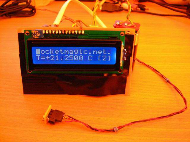
Since I had two DS18B20 sitting among my other electronic components, I’ve decided to hook one up to my ATMega8 test board and see if I manage to get some temperature readings. One wire to a microcontroller’s pin, and two other wires for 5V power.

Now we’re ready to go… well not quite, this is a digital sensor and first we need to understand the way it communicates.
I’ve also found some good resources online here. If the link doesn’t work for you, see the attached PDF.
Here’s my source code, to get you started right away:
atmega8_lcd_temp.zip
2009/11/27: Changed delay function in therm_ds18b20.c .Download here.
Bottom line, this sensor offer some impressive results, and works very well. It is a good addition to any microcontroller board for gathering some extra environment parameters, and all at the expense of a single PIN on the microchip.
2011/04/14: asmika uploaded a custom variant with the following changes:

“I have rewritten the code a bit, so it can be used with ds18s20 (therm_18bs20.c. Small changes / fixed passing of LCD.H as they pass my test print. even small changes in the code change the display. ”
Can be obtained from here: tempi
October 7, 2012
The code has been updated to correctly parse the sensor’s data. See the new article here. The code from 2009, above, is obsolete, do not use!


Hi friend y need your help, the connections of lcd does not work, i was built all the hole circuit and it does not work, what function has the PORTB |= 1, this pin in your circuit diagram does not have connection, y simulate the circtuit with proteus 7.5, help me please, i from mexico, thaks a lot fried, e-mail me please withe the hole funtional circuit, thanks.
Hi again my e-mail is carlos_lopez753@hotmail.com, give your e-mail and talk about this circuit, thanks
hola Carlos,
are you trying to connect the LCD to the Micro controller or do you also need the temperature sensor?
What microcontroller are you using and what LCD?
You can also check http://www.pocketmagic.net/?p=447
adiós!
Hi Radu i’m again, i use the same MCU Atmega 8 and LCD is HD44780 is the same like yours, i make all the circuit with proteus, and it does not work, can you speak spanish? i’m not write and speak english very well, can you give me your e-mail, for give you the diagram, i tried 4 times for make the circuit and not display nothing, it work but does not display the temperature, help me please, can you give the right circuit diagram, o can you tell me what can i do for resolve the problem, thanks my friend my e-mail is carlos_lopez753@hotmail.com,
Take Care Radu see you.
Hi there,
I’m in the process of building a multi function temperature display using an Atmega 128 board and a TFT display from http://www.shop-en.display3000.com/index.html. Do you know how to wire in two DS18B20 chips into the above board?
Any help would be greatefully appreciated
Kind regards
Adrian
Hi.
I made all the circuit with proteus but it didn’t work. I think i have same problem with Carlos. I need to know how to repair this circuit. Can you make contact with me.
My mail
ahmetnas@gmail.com
Thank You
Carlos & Ahmet, my email address is radu.motisan@gmail.com
Send me your circuit diagrams, and I’ll see what I can do.
Adrian, simply choose two input pins on the atmega128 and connect two separate sensors.
At the beginning you must add 4k7 Ohm resistor between the DQ and VDD.
Didn’t realise it was that simple 🙂
Thank you Radu.
I admire to your writing
need some help with the display.
the above circuit does not work for me
the display does not show anything, even the dimmer does not work
any suggestion?
Hi seek,
See http://www.pocketmagic.net/?p=447 for more details on the LCD usage.
Hi Radu,
After displaychange i get some result on the lcd.
But it always shows T=+127.9375 C
Thanks for fast response!
Greets
seek
Ok, that problem is caused by the delay function inside therm_ds18b20.c
I’ve updated the source code, see:
http://www.pocketmagic.net/wp-content/uploads/2009/03/therm.ZIP
Thanks Radu!
Can you please provide a updated .hex including your latest changes, please?
regards
seek
Unfortunately I don’t have the compiler on this computer, but I should be able to do it tomorrow.
What microcontroller are you using?
I do use the Atmega8 linke you.
Same problem here, no compiler available.
Thanks for your fast response the solving the problem.
I’ll check again by tomorrw.
Regards
seek
I tried to compile it myself using winAVR, but i’m getting an error like “interrupt …”
Therefore I’ll wait until you provide the .hex file with your actual changes.
regards
seek
error code interrupt/exception caught (code = 0xc00000fd, addr = 0x4217b3)
Hi Radu,
I’d love to continue my studies, but doing so means I need the newly build .hex file.
ö) seek
any news yet?
hopefully you’re ok radu, maybe on holiday?
still no working version…
a bit disapointed
Hi seek, sorry for the late reply: I didn’t have the chance to re-compile the hex yet. Please provide more details on the error messages you’re getting, so I can try to assist you in fixing those.
well radu, was mentioned before, you can’t compile the set you provided weather the original one, nore the one with the new files you uploaded.
this is the error code: error code interrupt/exception caught (code = 0xc00000fd, addr = 0×4217b3)
you should be able to set up a new .hex aren’t you?
Well simple tasks become complicated when you work 14 hours per day, but I’ll do my best.
Radu
i’m confident you’ll do this perfectly, radu
hm, maybe the spam checking system should be overhauled ,-)
Hi Radu!
Any news on the new Version yet?
Well, after one and a half month of no further updates it seems like the project is dead, if it wasn’t that before at all.
someone could say disapointing, i’ll say: you ever learn….
sir i made the connections as it is but still my lcd is not working.please do the needfull help
sir iam doing 1 wire temperature sensor project, i made the connections but still my lcd is not working.please help me.
Len, do you have a reset button too? Is the LCD working after you press the RESET button?
I am planning to update the LCD code, but didn’t have the time for it yet.
sir i dont have reset button,i’ll make the changes.please can you send me the code to my email id in a single zip folder i am confused with many files over here which one to use .please sir
sir i am using 16*2 lcd – LM016L lcd please do the needful help,i am using proteus 7.1version i dont find any reset button in it.I have already sent u my circuit diagram please suggest me any changes required.please send me the code to my gmail id .
sir i got stuck up with my lcd display. please help me
Len, the problem is that my code is for the HD44780 LCD. I don’t have any LM016L arround.
sir can u please mail me the complete modified code of the project for hd44780 lcd,i’ll try to change the lcd and test the project.
sir i am trying to simulate the project using proteus but i am not getting anything on the display please help me.
sir can i use any 2*16 lcd using this code,is this possible.
Hi len, this code is for the hd44780 LCD display only.
sir do you have the proteus simulation file,can u please post it sir.
sir how could i simulate the code it is by avr studio or any other software.
please post the proteus simulation file.
Radu, nice job. can you provide me the same for lpc2131 ARM processor?
really needed help bcoz have a project to be submitted by coming Wednesday.
if not on ARM processor can you provide me with the same for atmega 8?
please reply as i have to get ready by monday!
Hi everybody,
I’m trying to make a simple temperature measurement using AVR & DS18B20. I read all necessary documents and understand how it works. I also ran several simulation and my circuit worked well. But when used PCB to complete my work, the problem occurred!
My problem is when i test my PCB (of course i soldered all components on it) it can not returned a right temperature at all. there are 9 bytes reading form DS18B20 : E0 FD 00 00 1F FF 10 10 0E so the returned temperature around 94 degree C!! I tested my READ and WRITE SCRATCHPAD and they worked well and PCB as well. I’m really puzzling with it. i went over both hardware & code so many times but could not find out any fault.
Here is my complete code :
#include
#include
//===========================================
#define PA0 0
#define DS18_PORT PORTA
#define DS18_DDR DDRA
#define DS18_PIN PINA
#define DS18_DQ PA0
//—————————-
#define DS18_INPUT_MODE() DS18_DDR &= ~(1<<DS18_DQ)
#define DS18_OUTPUT_MODE() DS18_DDR |= (1<<DS18_DQ)
#define DS18_LOW() DS18_PORT &= ~(1<<DS18_DQ)
#define DS18_HIGH() DS18_PORT |= (1<<DS18_DQ)
#define URSEL 7
#define UCSZ0 1
#define UCSZ1 2
#define TXEN 3
#define UDRE 5
//================================================
void rsInit()
{
UCSRA=0x00;
UCSRC=(1<<URSEL)|(1<<UCSZ0) | (1<<UCSZ1);
UCSRB=(1<<TXEN);
UBRRL=51; // baud rate 9600 bps
}
void rsSend(unsigned char data) {
while( !(UCSRA & (1<<UDRE)));
UDR = data;
}
unsigned int DS_RESET()
{
int i;
DS18_OUTPUT_MODE();
DS18_LOW();
delay_us(480);
DS18_INPUT_MODE();
delay_us(60);
i = (DS18_PIN & (1<<DS18_DQ)) ;
delay_us(420);
return i;
}
void DS_write_bit(unsigned int biit)
{
DS18_OUTPUT_MODE();
DS18_LOW();
delay_us(1);
if(biit) { DS18_INPUT_MODE();}
delay_us(60);
DS18_INPUT_MODE();
}
unsigned int DS_read_bit(void)
{
unsigned int biit = 0;
DS18_OUTPUT_MODE();
DS18_LOW();
delay_us(1);
DS18_INPUT_MODE();
delay_us(14);
if(DS18_PIN & (1<>=1;
n|=(DS_read_bit()<>= 1;
}
}
unsigned int CONVERT (float value)
{
value *= 0.625;
return value;
}
void main()
{
unsigned int temp[2];
unsigned int digit;
unsigned int decimal, dec;
rsInit(); // init rs232
while(1){
while(DS_RESET()); // 0 OK, 1 WRONG
DS_write_byte(0xCC); // skip rom
DS_write_byte(0x44); // convert temperature
while(1)
{
while(!DS_read_bit()); //return 0 if convert complete
while(DS_RESET()); // 0 OK, 1 WRONG
DS_write_byte(0xCC); // skip rom
DS_write_byte(0xBE); // read scratchpad
temp[0] = DS_read_byte(); // read Byte 0
temp[1] = DS_read_byte(); // read byte 1
while(DS_RESET()); // stop reading scratchpad
digit = temp[0] >> 4;
digit |= (temp[1] & 0x7) << 4;
decimal = temp[0] & 0x0F;
dec = CONVERT(decimal);
rsSend(digit);
rsSend(dec);
delay_ms(1000);
break;
}
}
}
i appreciate any support and suggestion!
Hi. I want to make a thermostat form your project. Can anybody show me how to make function “if” in my main program? Which parameter should i compare to work it out? I barely know c++ so there is my problem.
Thanks for any help:)
@Tantho, please check the speed settings, the F_CPU constant, and the makefile for your project. Check the delay function, the delay_ms and make sure it is accurate! These issues can cause the problems you’ve described, because of incorrect timing. If you look in the sensor’s datasheet you will see it requires precises commands at precise moments.
Hello Rafal, did you try my code directly? Are you trying to change something?
Yes, i wat to add something like this to your code:
#define ledon DDRB |= _BV(0);PORTB |= _BV(0);
#define ledoff DDRB |= _BV(0);PORTB &= ~_BV(0);
.
.
.
if ( ___ < 24 ) // where 24 is the border temp., if temp. goes down the heating should turn on
{
ledon;
}
else
{
ledoff;
}
I don't know what i should put in " ___ ", what i should compare in "if" function?
I did try to use your code, and I had a little problem. But works fine if you use a pull up resistor of 4K7 on the DQ pin of the sensor.
Thank you Radu!
Thanks, Florin!
@Radu Motisan
Thank you for your help. I solved the case. The cause was that i had bought fake DS18B20 sensors!! After 3 week, i decided to buy 2 new sensors from different store and with the same code they worked properly!
Regards,
TanTho
Hello Tantho, thank for your update, glad that it works!
@Tantho:
Verify if you had acquired the DS18S20 in your first attempt. It is an old version and should be treated using other algorithm.
Have a look to http://www.maxim-ic.com/app-notes/index.mvp/id/4377
Rgds.
Radu,
Unfortunately, your code is not working for negative values. So, if somebody needs to read also negative values, should change the code.
Another problem I have with the circuit (just for others that have this problem): Using only the 4K7 pull up resistor worked perfect for short wires, but when I assembled everything using a 3-4meter cable the temp reading was not working. So, I have changed the 4K7 resitor to a 2K2 resistor, also added to the +5V and Ground pins a 10uF capacitor. Now it works. Also, I found on the internet that also a 100R resistor on the Data pin helps, so I added, but I don’t see differences.
Best regards,
Florin Vasilescu
Salut Radu!
I have a question for you. I’ve downloaded the arhive and I saw that the .hex file size is 8.62KB. Is the Atmega8 flash space enough? It has 8KB. After flashing, the microcontroller will be full? I am asking you that because I have never did that before and I want to know what atmega I should buy.
Thank you very much! You’re doing a really great job with these tutorials!
@Rafal – I think you should use the second function, therm_read_temperature2(digit, decimal). This will give you the temperature in integer.
if(digit < 24) {
start_heating();
}
Hello Iulian!
The hex file is indeed bigger then 8K (8834bytes) but it contains information represented in text format as hex numbers.
eg. :10 00 00 00 …
This sequence needs 9 bytes to be stored in the hex file, but it only represents 4 bytes: 0x10, 0x00, 0x00 and 0x00. So the 8834bytes file will occupy a much smaller amount of memory when written in the microcontroller.
Hello Florin,
Thanks for the valuable feedback!
I didn’t run tests on negative temperature , but I will have that in mind when updating this code.
Thank you very much! I understand now. I will use a nokia 3310 lcd display and I will have to flash the atmega with display’s libray too, which is quite big.
Hi Radu, I’m using your code and everything seems to work just fine.
-Except, I get Temp 2.8125 C when my store-bought Thermometer says 22.1 C in the same area. What to do? I don’t know very much about this. Thanks.
@nikolai: try to put a 4.7K resistor in parallel between +5V and DQ.
file therm.zip from 11 27 2009 contains globals.h, which points to
# include “therm_ds18b20.h”
# include “pir.h”
# include “led.h”
# include “ping.h”
But where can I find those files?
also point to
#include “avrlibdefs.h”
#include “avrlibtypes.h”
#include “a2d.h”
#include “uart.h”
#include “timer.h”
#include “i2c.h”
#include “servo.h”
#include “lcd.h”
#include “pushbutton.h”
You don’t need those for the DS18B20 , feel free to comment them.
Still 2.8 degrees.
After rewriting of the new files from therm.zip ( and with 4k7 )
Does anyone have the hex file that works?
I have rewritten the code a bit, so it can be used with ds18s20 (therm_18bs20.c. Small changes / fixed passing of LCD.H as they pass my test print. even small changes in the code change the display. Can be obtained from http://fjelltur.org/tempi.rar
Image is on http://fjelltur.org/temp.jpg
@asmika thanks for these changes, I’ve added them in the main post.
Change these 2 lines, and it measures a negative temperature.
From:
digit=8*temperature[0]>>4;// *************** husk å fjerne 8* ***************
digit|=(temperature[1]&0x7)<>5;// *************** husk å fjerne 8* ***************
digit|=(temperature[1]&0x7)<<5;
But it seems to show a degree for little when it is negative (-3.5 C ice 2.5 C)
Changed a little bug
fjelltur.org/temp1.rar
HI RADU MOTISAN, i create this your project and have problem. When i don’t have senzor connected show +127.9375 C, why not show error or 00.0000 C? and when its temperature + show ok, when its temperature – show -127… 🙁 why not -00.000 ? can you help me…BYE
can who me help me about this negative temp.?
There are certainly several ways to do this.
And certainly depends on the lcd.c
I use the variant that I found on http://www.pocketmagic.net/?p=473
As long as there are positive temperature goes smoothly.
But the three-digit hexadecimal must be divided into an integer, and a Faction (behind the coma)
Temp FF0h is -1 (FF is integer, 0 is 0 / 16)
Temp FF8 is -0.5 (FF is integer, 8 is 8 / 16)
If there is a x/16 behind the comma, the integer value is reduced by 1
Was this useful? If not ask again.
first, thanks for your help asmika! respect
second, I am a beginner in programming.
i did make this project^^with ds18b20 senzor and atmega8, and don’t work negative temperature! it would be nice if the owner repairs.
However, I want to fix itself.
this is program for read senzor?
what should be changed for work a negative temperature?
void therm_read_temperature(char *buffer)
{
// Buffer length must be at least 12bytes long! [“+XXX.XXXX C”]
uint8_t temperature[2];
int8_t digit;
uint16_t decimal;
//Reset, skip ROM and start temperature conversion
therm_reset();
therm_write_byte(THERM_CMD_SKIPROM);
therm_write_byte(THERM_CMD_CONVERTTEMP);
//Wait until conversion is complete
while(!therm_read_bit());
//Reset, skip ROM and send command to read Scratchpad
therm_reset();
therm_write_byte(THERM_CMD_SKIPROM);
therm_write_byte(THERM_CMD_RSCRATCHPAD);
//Read Scratchpad (only 2 first bytes)
temperature[0]=therm_read_byte();
temperature[1]=therm_read_byte();
therm_reset();
//Store temperature integer digits and decimal digits
digit=temperature[0]>>4;
digit|=temperature[1]<<4;
//Store decimal digits
decimal=(temperature[0]&0xf);
decimal*=THERM2_DECIMAL_STEPS_12BIT;
//Format temperature into a string [+XXX.XXXX C]
sprintf(buffer, "%+d.%02u", digit, decimal);
}
if anyone can help with this, i will be happy.
Thank you very much because you answered "asmika".
bye
nobody knows?
//Store temperature integer digits and decimal digits
neg =0;
tall=temperature[0];
tall2=temperature[1];
tempt=tall2*256+tall;
tall2=tall2%16;
tall2 =tall2*16;
//if (tall2>0){tall2=128;}
//tall=0b111111101;
decimal=10000/16*(tall%16);
//if(decimal>1){decimal=1;}
digit=tall/16+tall2;
if(digit0&neg==1){digit=digit+1;}
if(neg==1){digit=digit*(-1);}
//tempt=digit*16;
//tempt=tempt+tall%16;
if(neg0)sprintf(buffer, “-%d.%01uC”, digit, decimal/1000);
}
The disappears parts when I paste
if(neg0)sprintf(buffer, “-%d.%01uC”, digit, decimal/1000);
}
wrong again
is very difficult to change … :/
check here
http://avrsia.priv.no/txt.txt
asmika work!!! negative !!! 🙂
Please post your work program with negative on site for others…:)
thank you!
bye
http://avrsia.priv.no/tempneg.rar
http://avrsia.priv.no/tempneg.jpg
-0.6 Is the normal view, fff5 is the same value in hexadecimal
bottom line is the max and min, in hexadecimal
http://avrsia.priv.no/tempneg.rar
http://avrsia.priv.no/tempneg.jpg
-0.6 Is the normal view, fff5 is the same value in hexadecimal
bottom line is the max and min, in hexadecimal
Hi. I have a problem with this code. I use a DS18B20 with ATmega32. I modified only the delays….i went with #include and put _delay_us() instead of therm_delay(us()). The program doesn’t work. It remains stuck at line : while(!therm_read_bit()); in the therm_read_temperature2() function. The only way it writes something on uart is when i connect a 5V to te uC pin where the sensor should be. Did anyone have this problem? Any suggestions?
asmika, its possible to change to 2 decimals?
find “sprintf(buffer, “%+d.%01uC”, digit, decimal/1000);”
Remove 0 ( zeros ) in “decimal/1000” and you get 2 , 3 or 4 digits.
but the resolution is only 1 / 16 C from ds18b20
so it will be small jumps already at 2 digits
Suggestions for those who want to experiment with an advanced variation.
program read several sensors on ” one wire bus ”
http://mathmed.blox.pl/2010/09/Uzyskanie-odczytu-z-pojedynczegowielu-termometrow.html
what i must change for 2 decimals? 0.05…
sorry for the delay in approving the comments, I’ve been away. Flash did you manage to finish the code?
find “sprintf(buffer, “%+d.%01uC”, digit, decimal/1000);”
Remove 0 ( zeros ) in “decimal/1000″ and you get 2 , 3 or 4 digits.
“decimal/1000″ //1 digit
“decimal/100″ //2 digit
“decimal/10″ //3 digit
Hi,
Your code works on ATMEGA328P, however you use THERM_DQI in therm_ds18b20.c which does not exist, should be replaced by THERM_DQ.
Thank you
Hi, I have connect LCD, atmega16 and DS18B20. In proteus i always have 127C temperature. So how solve this problem? 🙂
void therm_read_temperature(char *buffer)
{
// Buffer length must be at least 12bytes long! [“+XXX.XXXX C”]
uint8_t temperature[2];
int8_t digit;
uint16_t decimal;
//Reset, skip ROM and start temperature conversion
therm_reset();
therm_write_byte(THERM_CMD_SKIPROM);
therm_write_byte(THERM_CMD_CONVERTTEMP);
//Wait until conversion is complete
while(!therm_read_bit());
//Reset, skip ROM and send command to read Scratchpad
therm_reset();
therm_write_byte(THERM_CMD_SKIPROM);
therm_write_byte(THERM_CMD_RSCRATCHPAD);
//Read Scratchpad (only 2 first bytes)
temperature[0]=therm_read_byte();
temperature[1]=therm_read_byte();
therm_reset();
//Store temperature integer digits and decimal digits
digit=temperature[0]>>4;
digit|=(temperature[1]&0x7)<<4;
//Store decimal digits
decimal=temperature[0]&0xf;
decimal*=THERM_DECIMAL_STEPS_12BIT;
//Format temperature into a string [+XXX.XXXX C]
sprintf(buffer, "%+d.%04u C", digit, decimal);
}
Hi. i would like to modiffy this wonderful project / tutorial to make differential thermometer, but dont know about the coding part
Things i want to do
* add 3 or 4 sensors in total
* decrease precision from .0000 to .0
* display values something like this (because of limitations of 16×2 LCD)
T1=+30.0T2=+40.7
T3=+50.5T4=+15.3
* i want to know correct place in code where i could put my own algorythm to control relay / diodes
Pingback: ATMega8 Temperature Sensors DS18B20 and DHT11 « PocketMagic
The code has been updated. See first paragraph of the article.
Code you post have errors.
If you want to help people please don’t get them lost in code you didn’t finish.
Thanks for code, it is good for all to get it, but if you want to share something and after sharing listen how code doesn’t work and answering using generic answers…then it is not ok.
What I’m talking about:
in file therm_ds18b20 you use THERM_DQ,
after that you write THERM_DQI.
If you show people that you have code that work, then send them that code, not something which actually doesn’t work.
Hope this will be understood as critic, not something else.
Code should be corrected and posted if there is desire to share it…else don’t share.
Thanks!
@Critic, it is a bit too much to call the code “with errors” or “not finished” just because a variable was named DQI instead of DQ. The funny thing is you don’t see the complexity of the sensor algorithm, that is done and works correctly, but you have a problem with a misnamed variable of secondary importance 🙂
Nevertheless the code you are referring to was written by asmika , not me. But for your convenience, I have changed the variable name from THERM_DQI to THERM_DQ, something you could have easily done yourself.
Be careful, that is an old version, you should use the latest! (October 7, 2012)
sir, may i ask u, what about if i use atmega16 for digital temperature DS18B20 using AVRCompiler? i hope u can help me,
I want to change the Lcd pins …
I change the data pins to PB0 PB1 PB2 PB3 AND MY RS IS PD2 AND EN IS PD3 ..AND THE TEMPRATURE SENSOR IS ON PC5 ….SO WHAT CHANGES I HAVE TO MADE IN THIS .
ALSO EXPLAIN THE DDRB =1 MEANS AND IF (i %2)
PORTB=1 MEANING IN THE MAIN PROGRAM…
Hi, BRO IT DOSE NOT WORK!!!
Hello, this ds18b20 library not working with minus temperature.