
Featured on Hack a Day:
The Capacitor discharge microspot welder has been featured on HaD, see it here . Thank you guys!
The circuit diagram and complete source code is available at the bottom of this article. This project is based on Jiri Pittner’s welder for the Atmega16, and so the source code (Below) is released under GPL.

This project took a lot of time to complete. This article is structured on several parts, the bottom containing the final results. The microcontroller source code for the Dual Pulse Welder/Cutter is included at the bottom part of this article.
Progress summary:
2012-02-08, First tests
2012-02-09, Choosing the LCD
2012-02-22, 1,000,000uF Capacitor update
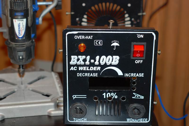
2012-03-01, Project box
2012-03-03, Power supply and some innovative electrodes
2012-03-18, Tungsten electrodes
2012-07-15, Source code and circuit diagram
Part 1: February 8th, 2012
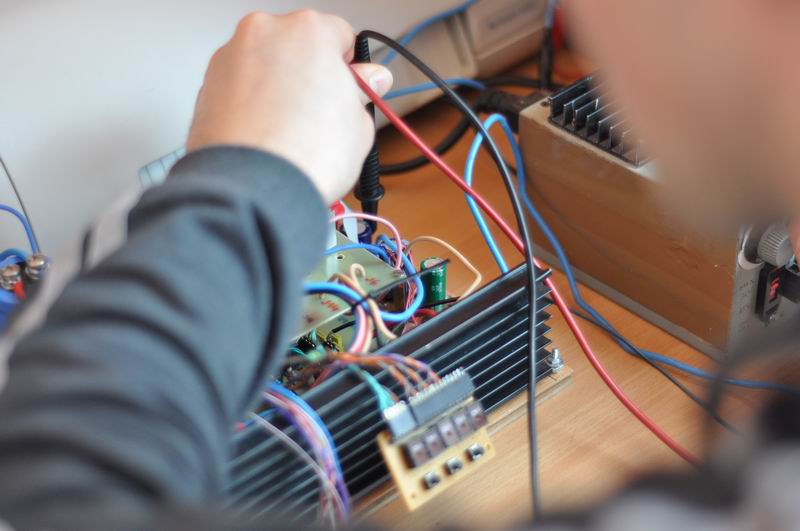
I’ve just completed the first tests of a new challenging project, a pulsed discharge micro spot welder and cutter tool. It stores energy into a huge capacitor bank, and discharges it via two electrodes in the given target, regularly metal foils/sheets. The logic and the precise timing (of the order of micro-seconds) is controlled by an AtMEGA16-16PU microcontroller running at 16MHz. It can be used for spot welding and for plasma cutting.
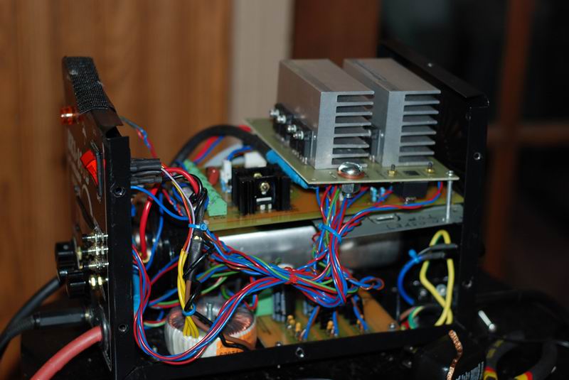
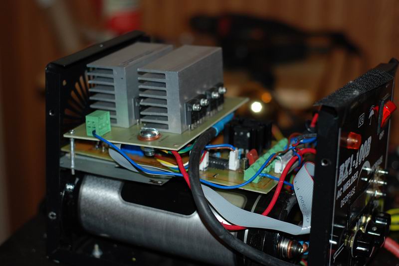
The power switch is handled by 5 power mosfets, IRFP2907, set in parallel and driven by a darlington array IC with further transistor amplification. A single mosfet is rated for 75V 209Amps and an extremely low Rds. Do the math for the 5 working together!
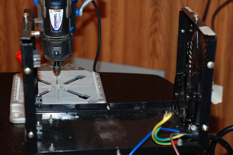
Here is one of the construction tests, where I cut a beer can:
The molten material sticks to the discharge electrodes, making the operation difficult. I plan to try manufacturing them our of Graphite or Tungsten. Let’s see which one works best!
This project is work in progress. My capacitors bank is aprox. 60000uFarad, but I need to get close to 1 Farad to have enough energy for correct operation. I will probably use a Car Audio capacitor.
Schematics, Microcontroller software, PCB layout to be added. Video showing spot welding will follow soon.
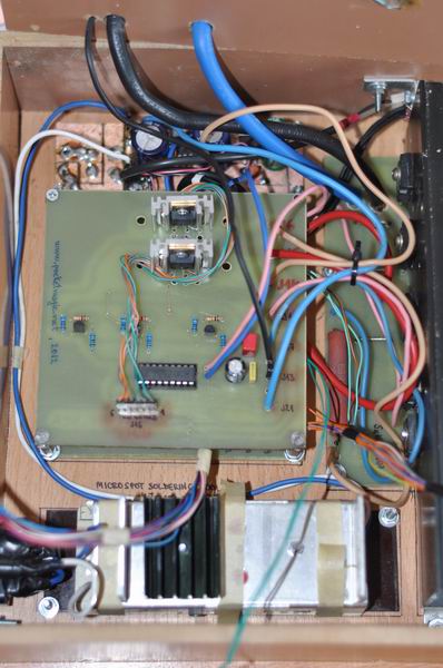
Some construction pictures:


The tool currently operates in two modes
1) Micro spot soldering
A predefined (uC+LCD+controls) high current pulse is delivered to the two electrodes, when the trigger button is pressed. Metal wires or sheets pressed between the electrodes will be soldered.
2) Cutting
A burst of short pulses are sent to the electrodes to generate plasma and cut thin metal foils.
The pulse duration, repetition rates are configurable. I got best results with pairs of pulses. Duration in the range of tens – a few hundreds of microseconds. For welding, the first pulse melts the material, and the second consolidates the soldering. For cutting the first pulse does the damage, and the second pulse helps to clean the electrode off the molten micro spot.
More operating modes can be added, so please give me ideas!
TODOs:
– I need to find better electrodes, that do not stick to the material , I’m considering tungsten or graphite. Suggestions?
– bigger capacitor bank: I need more power, and will probably go for a 1Farad Car Audio capacitor . Those Sprague I’m currently using are not enough for ticker sheets.
– finish and publish the software
– publish schematics and PCB layout.

Part 2: February 9th, 2012
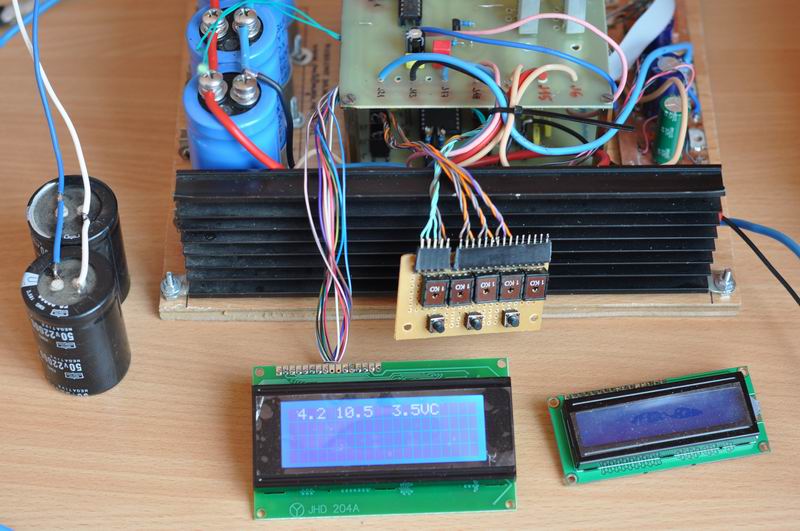
I need to decide what type of LCD to use: the 2 lines HD44780 LCD, or the bigger one, with 4 lines. The code I wrote works with both. The larger one would have the advantage of allowing more text to be displayed. The smaller one is on the other hand more compact, better suited for my small case.
Part 3: February 22nd, 2012
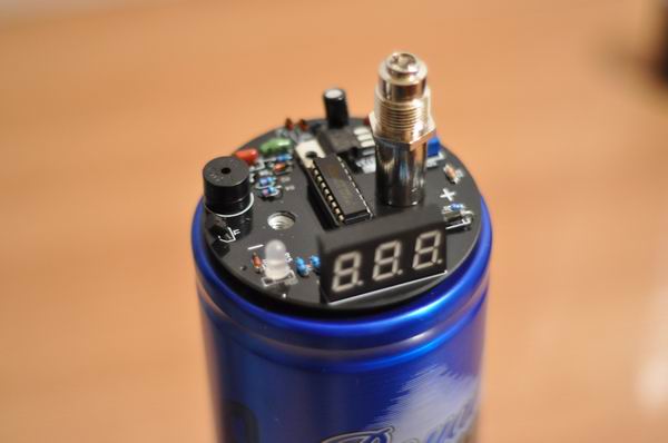
I purchased a suitable capacitor. Finally! It’s a Pyramid Royal Blue, CAP160DBL 1.6 Farads . The first thing I did was to dismantle the useless electronic part and the display. By doing so, the new size fits perfectly to my project box. For those complaining that this type of capacitor, when used for car audio systems, doesn’t switch off and depletes the car battery, simply unscrew the connectors to take off the display part. You won’t be needing that anyway:
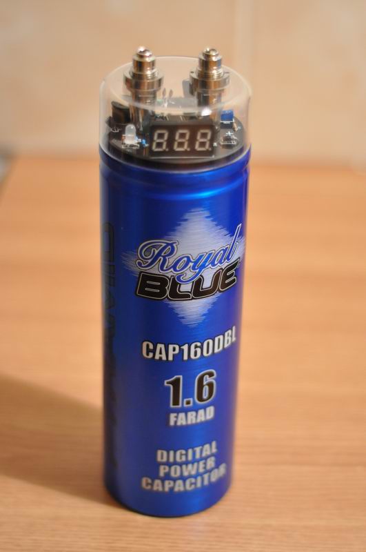
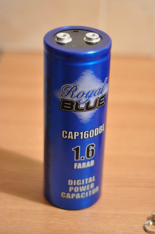
The price for this one was aprox. 55USD from a local shop and this makes it the most expensive component of this entire project, as expected.
Part 4: March 1st, 2012
The project box, in the final shape is ready. I had to cut some more wood, but that’s an easy task if using the proper tools (I got a nice pendular saw as a gift, last Christmas).
For a quick test I tried using a halogen 12V electronic transformer. That was a waste of time, as those things are unstable, and not working properly (they are barely oscillating):
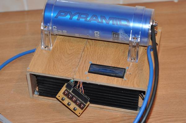
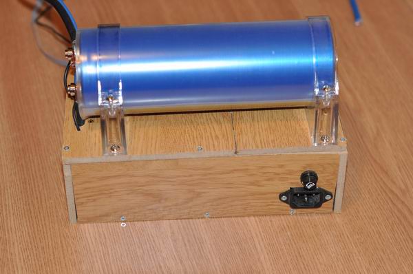
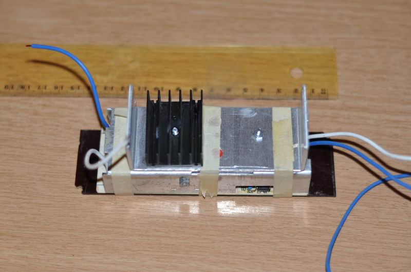
The box exposes the heatsink, a standard PC power connector, and a fuse holder. The big capacitor is mounted on the top, as it looks nice and is too big to fit inside anyway.
Part 5: March 3rd, 2012
I resisted the temptation to throw that halogen electronic transformer to the trash. It was such a waste of time! Instead I found a charger, from an old laptop. It is a 90W, 19.5V SMPS supply, with the perfect size for my box. Initial tests shown it is capable of charging the capacitor (with a short initial blackout), and even hold the intense Arc cutting mode power consumption. As this was another Chinese cheapo, some optional components such as filter, capacitors, etc where missing from the PCB, and I added those first. Next I did a heatsink upgrade, to make sure it will run continuously, for as long as I need to use the tool:


So far this proved to be an excellent choice! My device can now be powered from a 110V-220V outlet. Alternatively, you can choose one of the SMPS power supplies presented here.
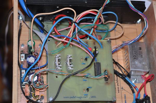
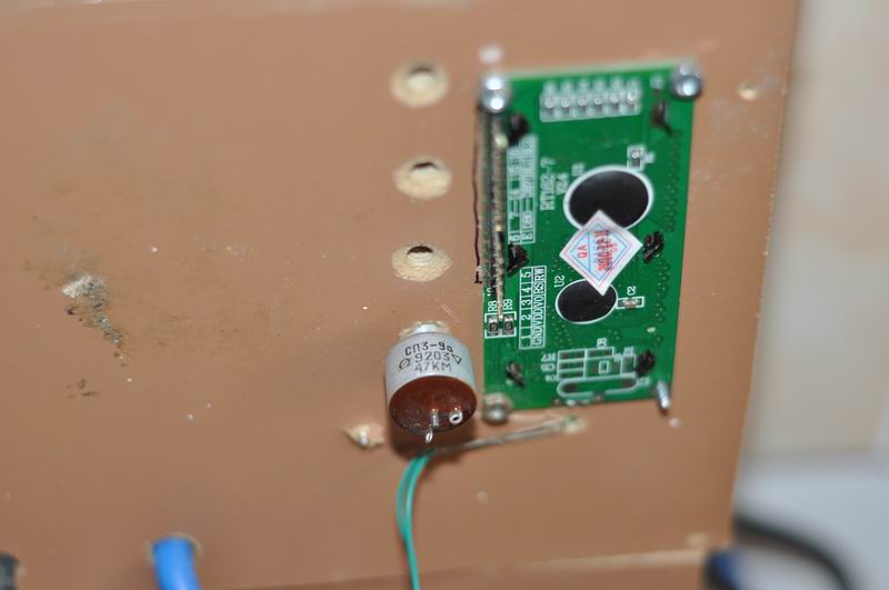
For the control panel, I needed a few potentiometers and some push buttons. I used a few NOS Russian 47K pots, I got from Gintaras Ebay show, KWTUBES. You can get some high quality components there at fair prices.

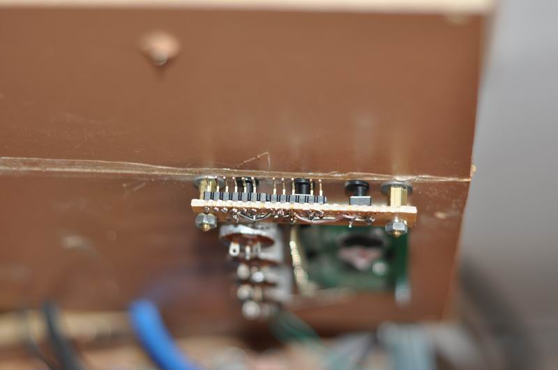
Some pins are used to interface with the floating cables coming from the PCB modules. By doing so, I can easily dismantle and re-mantle everything together.
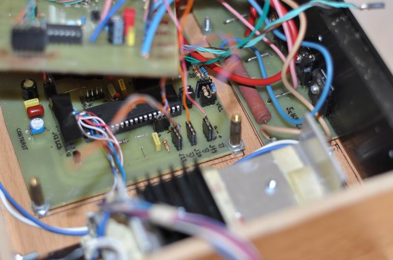
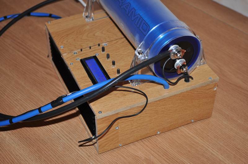
Here’s how the setup looks like now:

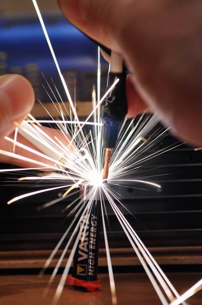
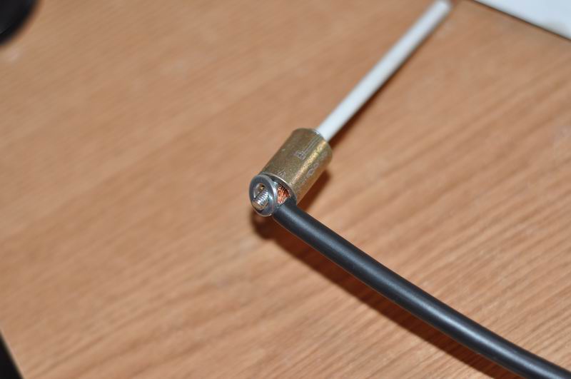
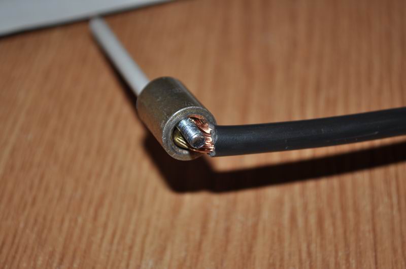
For the working electrodes I ended up using copper. But not just copper, also a new innovative design: the thick wires are connected to the electrodes using a screw, a screw nut and a washer. The electrode itself is a 10cm metal hollow tube. Inside, copper wire can be inserted, and while working, it can be pulled outside when needed. Exactly like a rotring pencil : the cooper electrodes is eaten while in use, but conveniently can be extracted from within the electrode, or replaced.

Here’s a video showing the working principle:
The positive electrode also holds the discharge command push button that can be pressed with one of the fingers.
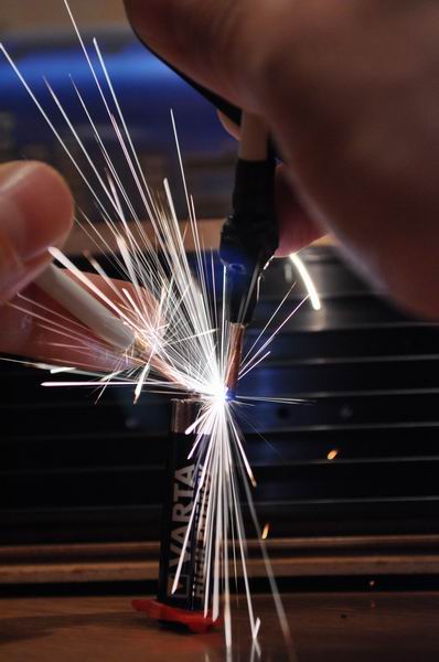
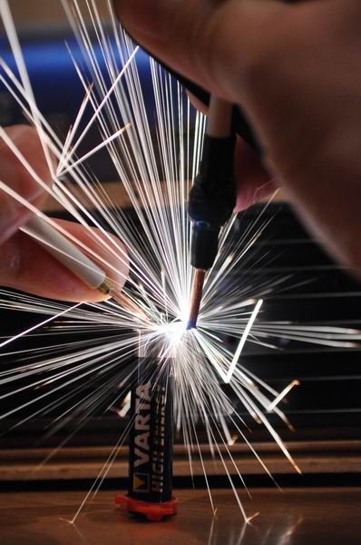
Finally, here’s the completed project:

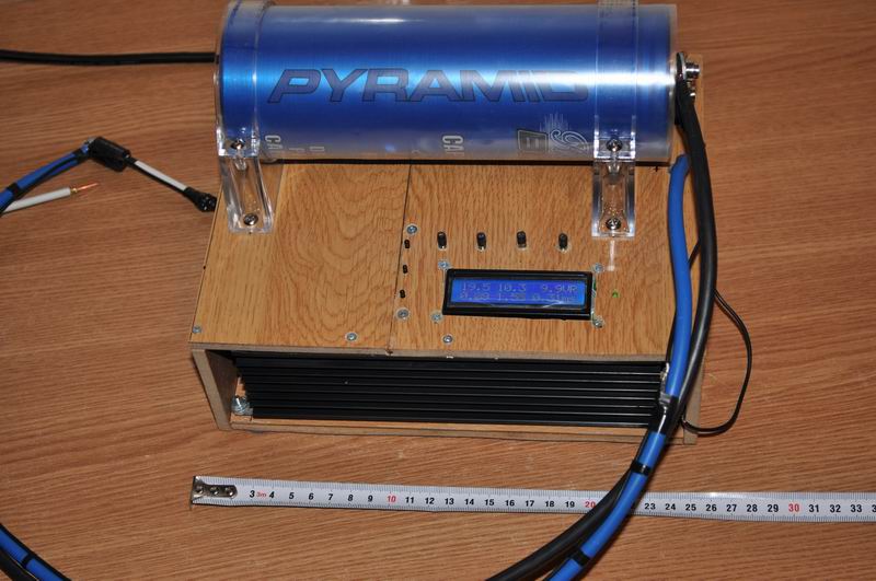
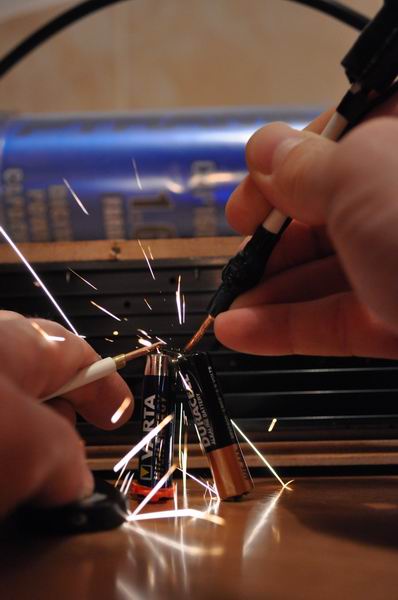
A few sparks, as recorded in some interesting photos, timing was crucial to get them, but I managed to do that eventually:


The power components are interconnected using thick copper wires. The wires to the electrodes are Copper Litz wire with section are of 16mm^2.
The 1.6F Capacitor that I used, has an ESR of 0.0016 Ohm.
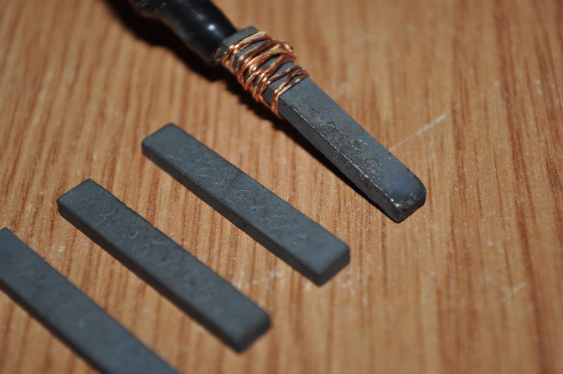
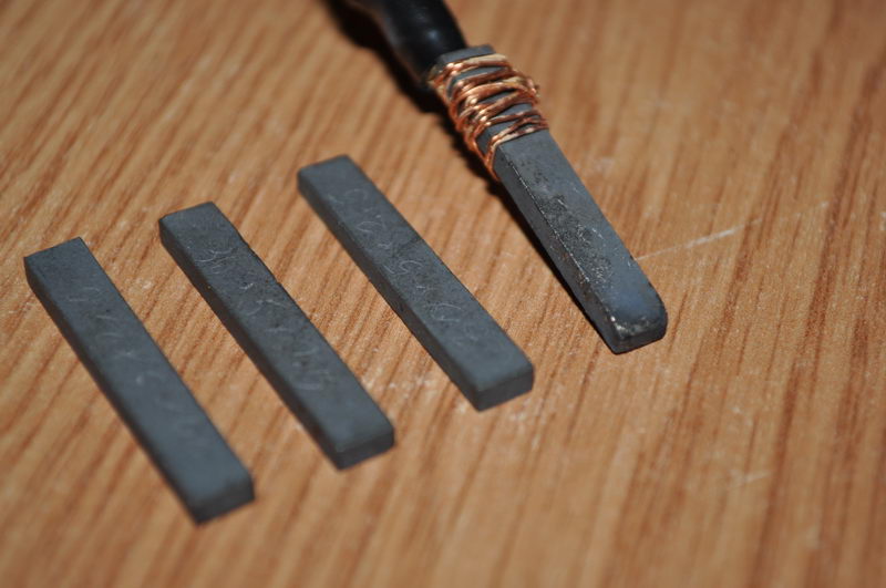
Part 6: March 18th, 2012
I recently received a few Tungsten Carbide rods. This excellent material has a high melting point (2,870 °C), it is extremely hard (8.5–9.0 Mohs scale) with low electrical resistivity (~2×10⁻⁷ Ohm·m) making it an good electrode material for the Capacitor Welder. I hope to see it solves the molten sticky metal issue I had with copper electrodes.
Results show excellent performance:
Here is another video:
After a few minutes of use, some signs of damage are observed on the electrode, but they are minor at least when compared to copper:
Components used:
There were many modules involved in this project, but I will try to mention the most important:
1] 5x IRFP 2907 21USD . Source . These were used in parallel, on the large heatsink, to switch the capacitor discharge on and off
2] 2x IRF2807 3USD . Source . One handles the charging and the other the discharging of the capacitor, to keep it at the predefined voltage level.
3] 1x ULN2803 5USD (10 pieces pack). Source . TRANSISTOR ARRAY-8 NPN DARLINGTONS used in the transistor driver board.
4] 1x Atmel ATMega 16-16PU 12USD. Source .
5] 1x 16×2 HD44780 Character LCD 3USD . Source .
6] 1x Power Supply 19.5V 4.5A 13USD . Source . I had a few of these laptop adapters and it seems they are well fitted for my Capacitor Pulse discharge tool, for both welding and cutting.
7] 1x 1.6F 20V Capacitor 50USD . Source: local car audio shop.
8] 4x 47K Potentiometers 9USD (50 pieces pack). Source .
9] Other 20USD (16MHz Crystal, connectors, switches, wires, etc)
Part 7: July 15th, 2012
Schematics:

The eagle PCH can be downloaded here.
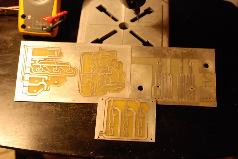
PCB Layout:

If you need to print the PCB for your own board, please use this PDF file.
Software, released under GPL License:
Here is my own software implementation, featuring the C++ LCB library that I described in a previous article:
Hex file and complete source code
Other resources:
You might also want to see Jiri Pittner’s welder, presented here.
Looking forward to see your own variants of this cool project!
Here are some variants created by my readers
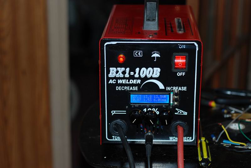
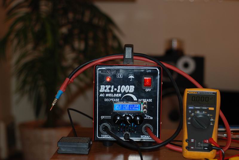
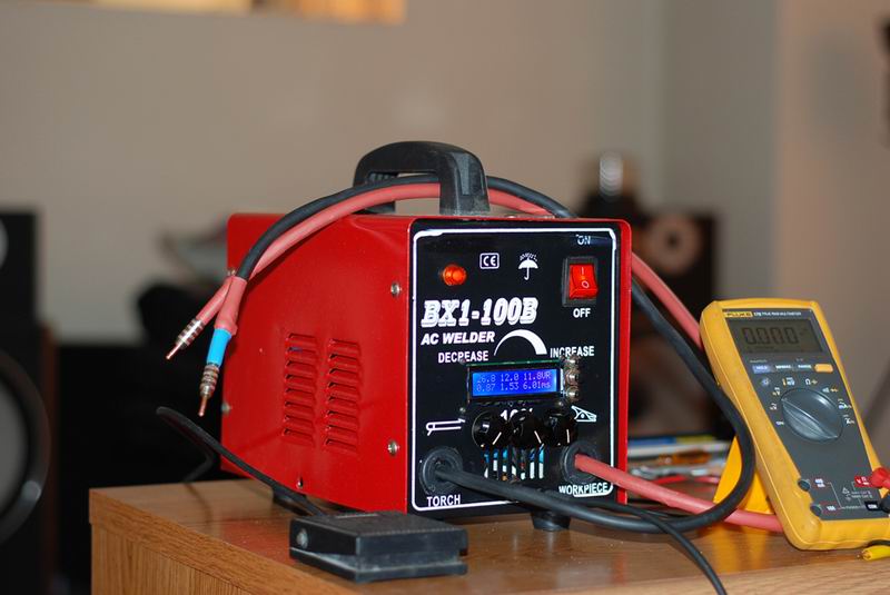
David’s capacitor discharge spot welder
David did an excellent job at building this tool, with a very nice case and a pedal as a trigger


Wow! Thats is very impresive! I didn´t know nothing about this tipe of cutter. Thanks you for share!
Thank you, Peter, but keep in mind these are only early tests. I still need to finish the software and use the proper capacitor. So stay tuned for the next updates/
Okey! Yes, I supose that this are test, but the information is very useful beacause Im building a little CNC and this can be a nice cutting machine. Sorry for my english, I don´t speak it very well. Thanks for your knowledge.
Peter.
O realizare ok pe care vreau sa o fac si eu pt …taiere CNC. O carcasa potrivita am,un traf de 12A am dar nu stiu unde gasesc sch si .hex/.asm .
salut Tyc, multumesc. Incerc sa pun schema si layoutul saptamana asta. Softul l-am dezvoltat in C, o sa pun direct si hexul.
.hex e ok ,programarea nu e punctul meu forte (de fapt e un minus).Astept cu nerabdare.
Am trimis lista cu componente ,condensatorii nu i-am comandat.
Eu mi0am luat recent un condensator de 1.6F auto, dar nu am avut timp sa il instalez. Sper sa pot cat de curand.
Ok tyc, functioneaza brici.
Cu electrozi ce se intampla ? Cum spuneam ,vreau sa o adaptez pt cnc si daca a pornit capul de taiere … .
Momentan va fi pe o freza manuala ;in principiu functioneaza si cnc -am vazut una la lucru si era cu flacara oxiacetilenica ,transmisie pe cabluri si ghidaje … sine de cale ferata .Masa era de 5*4m.
Desi piesa mea era de 20*10 cm ,a taiat-o la fix .Asta cu oxiacetilenic care nu prea are precizie ,cu spot trebuie sa iasa cu margini superfinisate -la oxi raman bavuri pe margini.
Din cate am inteles ,ai sacrificat o smps de laptop .Restul nu prea am inteles ,dar am vazut ca ai pus montajul intr-o carcasa de lemn meseriasa .
Carcasele din materiale inflamabile sant contraindicate pt dispozitivele care degaja caldura ,lucrezi cu schintei in proximitate ;se poate sa pierzi dispozitivul .
Ce inseamna layout in contextul de fata ?
Nu postezi niste linkuri spre sch si .hex final? In text trebuie sa fie indici dar din imagini nu reiese (cine nu stie engleza astazi are un handicap si nu in sens peiorativ ci direct – o analogie zice ca sant in fata unui text in en cu trimiteri indirecte,fara o mana si trei degete de la cealalta).
Multumiri in avans (suna cam naspa dar asa suna in en cu Gogu).
O varianta mai ieftina ar iesi cu mosfeti de pe placi de baza, au rezistenta mica si curent mare suportat, tensiunea lor mica nu cred ca implica o problema, nefiind vorba de o sarcina inductiva la iesirea lor.
Vreau sa fac o varianta cu astfel de mosfeti si acumulator auto, cat mai low-cost
@lorik199 sunt curios sa vad ce reusesti sa faci, idea e buna
@tyc
Pentru capul de taiere, eu zic ca tot sistemul de rotring e o alegere buna. Pentru ce doresti sa faci tu, ar mai fi nevoie de un resort, care sa preseze firul de cupru spre placa de taiat, in felul asta pe masura ce se consuma , electrodul e impins de resort, si taierea se face cu un electrod intreg. Dupa un timp , se pune o noua sarma de 10-15cm, care va rezista la un numar N de taieturi. E doar o idee, practica va zice ce si cum trebuie facut, dar cred ca dupa cateva idei bune si ajustarile necesare va functiona.
Inteleg problema la flacara oxiacetilenica. De unde se poate cumpara carbit?
Mi se pare complicat avand in vedere ca are nevoie de o sursa de acetilena si o butelie de oxigen, dar la tabla groasa nu cred ca este alta varianta. Poate un laser cu CO2 de putere mare, focusat cu o lentila in punctul de taiere.
Sursa de alimentare imi da 19.5V . In circuit am un mosfet de incarcare a condensatorului si un mosfet de descarcare. Descarcarea se face pe o rezistenta de 56Ohm 10W.
Asta pentru a aduce condensatorul la tensiunea aleasa din interfata. Cei doi mosfeti sunt IRF2907. Tensiunea maxima la care pot ajunge e 11.5V . Daca sursa mi-ar fi fost de numai 12V, cred ca de abia as fi atins 9V pe condensator.
Odata incarcat condensatorul, se descarca in electrozi prin 5 IRFP2807, care sunt pusi in paralel. Fiecare poate duce 209A maxim.
Avem deci 3 mosfeti care trebuiesc comandati, in mare cam asta face montajul: foloseste microprocesorul pentru a-i comanda conform setarilor. Asa se pot obtine tot felul de pulsuri de diferite lungimi si puteri.
Ma bucur ca ti-a placut carcasa mea. Am facut-o din resturi de parchet laminat, pe care le-am gasit la subsol. Mi-e forte usor sa lucrez cu el, il tai cu un soricel (fierastrau pendular) si prind placile cu suruburi de lemn. Am talpici rotunzi, din aia din pasla, ce se folosesc la mobila pe care ii pun dedesubt.
As vrea sa o fac neinflamabila, dar nu am aluminiu, nici menghina. O alternativa sunt carcasele de surse PC, le folosesc din cand in cand, dar pentru acest proiect se dovedeau neincapatoare.
PCB layout e schema cu trasee pentru realizarea circuitului imprimat. Din pacate nu am pregatire in electronica, si imi lipsesc unii termeni, poate mai potriviti.
La codul sursa vreau sa mai pun afisarea energiei in jouli, ca se calculeaza simplu la condensatori, iar SCH-ul sper sa-l pun in seara asta.
Nu se mai gaseste carbit ,doar butelii cu acetilena ;taierea la placi se poate face cu plasma ,plasma ,plasma si apoi cu oxiacetilena (pe la noi ) si jet de apa la metale moi .
Folosirea MOS-ilor de pe MB e o idee atractiva dar datorita EMI nu cred ca se poate in cazul de fata . Si supratensiunile pot fi create si prin efect capacitiv – exemplu : triplorul .
Eu as folosi doua carcase PSu ATX ,in modul duplex fara perete despartitor.
Great work! Thanks for sharing the idea and all the details!
That’s just pure awesomeness, thank you for letting us see it!
How about one of these puppies for a cap: http://www.ebay.ca/itm/2x-2600F-2-5V-Supercap-2600-Farad-Super-Ultra-Capacitor-/160598529850?pt=LH_DefaultDomain_0&hash=item25646b173a
I would love to make a batt tab welder for making batt packs for rc planes.
Put me on the list for your schematic and other docs.
I am oftren looking for battery tab dsolutions…
Thanks – great iea and an even better start !
Forget the naysayers – they’re mostly just trolls
Guys, I’m glad you like it, this tool works very well indeed.
@Aviator747, those caps are perfect for this purpose, actually they are a few orders of magnitude too good for the project, but if you can afford them, would work well: their ESR is low. You will need to put a few in series to increase the voltage to at least 12-13V. I suggest you get them from this seller: http://myworld.ebay.com/crpig/?_trksid=p4340.l2559
You can also use a car capacitor, like I did.
Battery tab welding requires at least 9-10V . Cutting requires 12V or more.
Will be putting the schematic and code soon, stay tuned!
cool post! Keep up the great work!
Thats really cool! I’ll be looking back at the progress for this. Was actually looking for another project to start this looks really interesting.
@McAllen will do.
@amar, yes, it’s a fun construction, and a useful tool as well
Awesome project!
Would a carbon based electrode provide better performance? I would imagine you would need some kind of material that does not melt easily to use as the tip so it doesn’t get stuck with the material you are working with.
I tried it, but Carbon didn’t go too well. It worked like there was a current limiting resistor. Tomorrow I’ll be trying Tungsten Carbide and report back,
Pingback: Capacitor Discharge Microspot Welder / Cutter » Road to 2012
well with the spot welding, have you thought of making it a one handed operation, with both leads going to a near point making it easier to weld?
I love this,
I hope you upload the schematic soon as I am interested in the principles of how everything works. I would like to use this as a guideline to build my final project in college around the second week of April as your result looks superb.
@kopeman, that’s an excellent idea. I designed two electrodes to allow using the device for multiple purposes. But for a given task, one could create a custom electrode having the both ends at a given distance, for easier operation, as you suggested. So depending on the application, this could actually save some time.
@Louis: I think this would make an excellent final project, as it is both an easy build and a useful tool. So I still have some work to do on the schematics, hope to finish it soon. Keep an eye on this page for updates.
Pingback: Nerd News » Blog Archive » Микросварочник-резак
Looks like a great tool to have. Keep us posted.
Pingback: A capacitive discharge welder/cutter for all your lightweight needs | Free Plans Online
Thank you for the hard work you put in documenting this project. I will be attempting to reproduce it myself, and I do hope you get the code and schematics uploaded to complete the amazing amount of information this project provides.
Sure Andje, the code is ready, the schematics still need some work, hope to finish it soon and update this post.
ps: you’ve got a very nice bike there.
Thanks!
My original bike uses RC lipo, and didn’t require anything special to build the battery. The new bike I am building will have hundreds of 18650v cells and I would like to weld them instead of soldering the end tabs together and forming a brittle connection. I am currently working with micro controllers in college; this project is exactly the kind of thing I can tackle to make my own ebike that much better :).
So as I said, thank you for the dev work you have done here. I figure I’m at least two years out on being able to truly start from scratch on something like this.
This is not complicated at all. You take one big cap, you charge it via a power supply (I used a laptop adapter), and you use a microcontroller or any other signal generator to command the capacitor discharge in predefined , short, pulses.
The switch itself is a number of high power trnasistors put in parallel (I used 5xIRFP2907, but that’s a bit too much. I feel 2 would have been sufficient).
As I said, schematics will follow soon.
Hi!
Really great what You have built here
Will the schematic and source code be available sometime?
Hi, i was wondering when would the shematics be available, because this works sound great to me, and i’d like to try it 🙂
Thank you very much,
nice job!
Good morning,Y am working on a pulsator magneto kinetic personal project witch is using chocks and percussion mechanic effect.This project need shorts electricals impulsions(between 0.10 to 0.001 second)with a maximum intensity.Can you let me know what are the limits of your impressive system? I hope you upload the schematic soon
Thanks for reminding me to do that . I’m still caught with a lot of work, hope to find some time for it soon, hopefully before I forget all the details 🙂
Radu hello.
Your project and very good, was a welder this type that I needed.
He is working well?
You said you would here the schematics and firmware soon, and that when you put them?
Thank you and good continuation of projects
Whatever.
This guy doesn’t share, period. He’s into glory, not the greater good. I wouldn’t waste time looking for schematics or code. What looks like a cool invention is just one man’s implementation of well-known prior art; maybe you could pay him for the details.
Or not.
Anyway, this is F’ing trivial to do, and all you have to do is google amateur EDM or capactive discharge machining. It’s basically the opposite of welding. You also don’t need a micro to do it, you can create PWM waveforms from trivial analog circuits and some gates.
Here’s a start, using a PIC programmed in BASIC. Mind you, these people are not exactly rocket scientists, but they don’t treat everything like a top secret VC wankfest, either.
http://bbs.homeshopmachinist.net/showthread.php?t=32118
If you look at my other posts you will quickly see that I share not only full design and schematics, but source code is also always included. So no reason to complain here.
I’ve got lots of things on my head and doing all of them as quickly as I can. I plan to post the schematics for this setup, but drawing them takes time.
Your patience is much appreciated. Thank you.
@Open Source. All details shared, as I took some time to draw the diagrams. Hope this helps
hi Radu Motisan.
Your project looks very good.
I would like to make a similar but with a PIC16F877.
Possive of you will be doing a description of your project both the cutting level as solder? How do you control the voltage of the capacitor?
Thank you and good continuation of projects
Hi Carlos,
The soldering works like this (you can also see it in the code):
PIN PD5 turns high , to command welding, for a very short amount of time, predefined using the user interface.
Then it waits for a short delay, predefined as well.
And finally a second pulse follows.
This is why you can call this dual pulse spot welding.
The cutting works by sending pulses repeatedly.
The charging of capacitors is controlled by bringing HIGH the pin PD4, it will command the Q2 mosfet, that charges the capacitor.
The discharge works in a similar way, bringing high the pin PD6, that opens the Q5 mosfet, that dumps the capacitor energy into the R13 power resistor.
The voltage on caps is measured using the ADC4 port, with the voltage divider made by resistors RVR2A and RVR2B.
The user can select the desired voltage in the interface, the software will continuously check it, and charge the capacitor or discharge it as need it, by controlling Q2 and Q5.
Let me know if you have any other questions.
hello Radu Motisan
What is the maximum and minimum time of the 1st pulse, the 2nd pulse and the waiting time between two impulses?
which the frequency of charging and discharging in the cutting mode?
thank you
I find this post very informative and would like to learn more about the capacitor and how it’s used. However, can you make the terms less technical? Thank you.
just wanted to thankyou for all the hard work you are doing and for making this open source so everyone can benefit really nice work.
@alberto: I’m glad it proves useful!
I first just want to thank you for sharing all your hard work. I am a noob and I cant find your pcb layout for the 5 mosfets. Any help will be greatly appreciated.
Thank you and great job.
Luis
have you considered using this as a power supply for a simple edm setup?
I’ve used it for corroding some small PCBs a few times.
Great work!
Would be nice to have an overall pattern of assembly or, at least, some pictures of the latest version. Thank you very much
Ciao Maurizio,
See pictures from Part 3: February 22nd, 2012 and newer. They show the latest version.
Good luck!
You might try increasing the voltage you are charging your capacitors at. By running your system at higher voltages, you can get a more consistance arc to your material at greater distances, making continuous cutting more reliable. Be careful not to raise it too much though, because you want to be able to control the location of your spark.
Indeed, Ryan, this is correct. Thanks for an excellent remark!
Hi Radu, I have followed this project across a few different sources(yourself, Jifi, UltraKeet) and would like to built your version. Just need to know whether the BOM supplied by Ultrakeet will work with your design? Of course excluding the PIC processor. Thanks
David, the principle is the same, the uC simply produces pulses delivered to the switching board. Please look over the schematics, to compare the content resulting in the BOM list.
Thanks for the quick response, I’ll look over the schematic. By the way, are there any Gerber or PCB files available on your design? Thanks in advance.
The PCB is in PDF format, attached at the end of the article.
I’ll post any success that I may have putting to unit together. Let me say this, I appreciate all your work and time that you have contributed to this project especially looking of the cost of a commercial unit of this type. Happy New Year!
thanks. happy new year!
Hello Radu, I am trying to sort out the PCB layout and Schematic that were provided from the download links above. There seems to be a few discrepancies between the two. For example I can not find the IRF2807s anywhere on the PCB layout. I do not want to move forward until I fully understand the relationship between the two. I am guessing you may have made some changes, but did not update the PCB layout or the actual PCBs. Another example is the power supply sections on the schematic: It shows three sections to the power supply and the PCB layout only shows two. can you add some clarity? Again, I appreciate your time and effort. David
@David, I’ll try to find time to publish an updated version of this project, including newer source code. But until then, please do the PCB changes yourself. It is trivial for the power supply section.
What did this project ultimately cost in parts?
It looks like it could make a great power supply for a wire EDM.
Thanks for sharing.
Nitrous
See PART 6: Components used for costs.
Hi there, I am in the process of ordering all the parts needed for the project, but I cannot find any information on the schematic stating the type of switches used for S1…S4. Could you be so kind and tell me what type of switches did you use? Thanks
david, they are all simple momentary push buttons.
s2,s3,s4 are mounted in the case, as seen here :
http://www.pocketmagic.net/wp-content/uploads/2012/02/kwtubes-3.jpg
and http://www.pocketmagic.net/wp-content/uploads/2012/02/welder_ready-3.jpg
and serve to control the software menu
s1 is mounted on one of the electrodes, and is used as a trigger for welding and cutting:
Radu, Thanks, I appreciate the quick response. Have a great day.
Hi Radu, Getting pretty close to assembling my parts, but I need to clarify one connection on the schematic. What pin are you connecting from Q7(IRFP2907) to the capacitor’s positive terminal? I am a little confused because the IRFP2907 symbol is upside down on the schematic. I would rather not guess which pin is implied here. Thanks as always.
Hi Radu,
I have almost 90% completed the circuit and assembled the boards as per your instructions.
Your project is just amazing, and thanks for sharing the info. including the source code.
One question, if I program the ATMega16 using ATMEL AVR Studio 6.0 and usWelder.hex, what should I set the fuse bit hi and low settings?
Please give me detailed info. as regards this matter.
Thanking you,
Jason
@David, it’s the drain going to capacitor positive terminal. Seems like the symbol is wrong. Also See: http://www.irf.com/product-info/datasheets/data/irfp2907.pdf
@Jason, thanks for reminding me to talk about the fuses. I don’t know how I forgot , probably I don’t pay much attention to this details. Anyway, here’s the fuze configuration, setting the atmega16 for an external , high frequency crystal (16MHz): avrdude -p atmega16 -c USBasp -U lfuse:w:0xff:m -U hfuse:w:0xc9:m
Hi Radu,
I just finished with your project and works amazing with the fuse bit settings as you have mentioned.
Some points I want to clarify is that the target capacitor voltage only increases / decreases in steps from 0.3,1.3,2.3….12.3,13.3 volts and vice versa (the top center LCD part) is that correct?
Secondly, my 1 Farad cap. voltage doesnot go beyond 10.8 volts, no matter what if I set the target voltage to 11.3, 12.3 or 13.3 it stays the same, my input charging voltage is 22.6 volts DC @ 8 amps current.
Is that normal too or I have done something wrong in programming?
Thirdly,in your usWelder.hex file, have you also taken consideration for a contact debounce switch delay of approx. 20 to 30 msecs for increamenting / decreamenting the target voltage setting and mode selection setting?
I have seen in your website photos you have incorporated 4 potentiometers first for Pulse1 second for Delay and third for Pulse2. What is the 4th potentiometer for?
Thanking you once again for this superb project.
Regards,
Jason.
@Jason, the software is set to increase/decrease the voltage on the capacitor in 1V steps.
To charge your 1Farad cap to a higher voltage, you will need to make a change to your device: connect the emitter of Q1 to Vcharge instead of Vdrive.
Please detail the following: “in your usWelder.hex file, have you also taken consideration for a contact debounce switch delay of approx. 20 to 30 msecs for increamenting / decreamenting the target voltage setting and mode selection setting?”
Regarding the 4th pot, it is currently unused, but planning to use it instead of the push buttons, for selecting the target voltage.
Don’t forget to send me pictures with your setup, I’m very curious to see it!
salut Radu,
Iti scriu urmatoarele ptr ca m-am impotmolit cu acest proiect . Cu programarea stau in pom si pomul e in aer . De o saptamana ma tot chinui sa programez ATmega16 si fara success. spune-mi te rog ce programmer sa cumpar si ce software sa folosesc pt programarea MCU. prima mea increcare a fost cu ALL-100A Universal Programmers bine-n-teles fara a scrie si Fuses , rezultatul a acestei incercari a fost un blank screen si a flashing led. La a doua incercarea am folosit pony programmer si AT-Prog.
Multumesc si astept cu nerabdare sfaturile tale.
Cu respect Iamandi
Salut Iamandi,
Ma bucur ca mi-ai scris. Partea de scriere a hex-ului nu e chiar atat de grea, si sper sa te pot indruma sa o faci cu succes. Eu folosesc programatoare ca si acestea: http://www.pocketmagic.net/2012/05/cheap-avr-usb-programmer/
Softul cu care scriu .hex-ul e WinAVR, dar e mai greoi de folosit pentru ca e in linie de comanda. Eu ca programator, sunt obisnuit. Iti pot recomanda “Extreme burner” care are interfata grafica.
Cat despre fuses, o sa pun un articol cu mai multe detalii, pentru ca mi-am dat seama ca am omis aceste aspecte in mai toate articolele mele si lumea are nevoie.
Deci Radu estiiiiiii “bestial” imi place proiectul tau ,l-am gasit cam tarziu , dar ma apuc de treaba, multumescc
ca l-ai facut public si pentru oameni care nu pot concepe “adica je”dar potsa-ti urmeze instructiunile si sa duca proiectul la capat.
Miii de multumiri!!!
Salut Florin,
Chiar ma gandeam recent ca de as avea timp as face unul mai mic, mai compact, cu piese mai ieftine.
Dar daca ti-e ok asa, te incurajez sa-l faci, eu il folosesc de fiecare data cand trebuie sa imi lipesc cate un pachet de baterii. Apropo, e destul sa folosesti si doar 3x IRFP 2907 .
Daca ai intrebari, poti sa le postezi aici, cand pot te ajut.
Hello Radu: I am trying to finish up things here, but I’m having some problems with the LCD. When I load the code that you provided above, I am getting garbage on the LCD display. Any idea what is going wrong here. Of course, I am using a HD44780 display as recommended and the processor fuse bits are lfuse=”ff” and hfuse=”c9″. Thanks
Disregard my previous post problem resolved. Thanks
Hi David, what was the problem?
On my PCB, J12 header had pin 6 and 8 shorting. Once, I fixed that issue, I can’t quite understand what your code is displaying on the LCD. I believe there are still some issues with the code. For example: On line1 the left column number never clearly forms a solid numeric number. It is updating so fast that you can barely make out the value. The second problem is the menu button if pressed multiple times, will cycle between the two modes than a third press of the button will generate random characters throughout the LCD display. Thirdly, the menu left right buttons only work on the middle column on line1 to increase or decrease the shown value. I am guessing I can mod the code if you could provide a brief explanation of what the LCD positions and values represent. Here is what I think the LCD is showing: line1 “Current Capacitor Voltage”, “Target Voltage”, and “Power supply voltage”. line2 “Pulse 1 duration”, delay between pulses, and “finally Pulse 2 duration”. Also, maybe some example setting values for those of us who are blindly attempting to complete such a project for the first time. Please understand that I am not complaining and appreciate all the time and effort you have put into this project, but at the same time regardless of an individual experience level, some clarity is always welcome. Thanks David
Hi Radu: No need to reply. All the information I need is in the source files. I guess I should have started there before posting. Thanks David
I would know if the code you write is compatible with spot welder of Fritz Geyser.
Best regards.
Leonardo
Radu: Thanks for the well documented C code. I finally got things sorted out with a few changes. Again, thanks for taking the time to share your efforts and recoding Jiri’s code in C++. I still have a few minor problems, but that’s due to the initial design by UltraKeet. Otherwise, I’m pretty happy with the results. Take care. @Leonard Hack: No this code won’t work for Fritz project. @Jason: I wouldn’t change Q1 emitter if your Vcharge supply is greater than 20V. The IRFP2907 has a max gate Vgs of 20v so be careful there. Another option is to change Vdrive supply 15V regulator to a 18V regulator. This will give you a max charging voltage of 13.8V instead of 10.8V. Unfortunately, that is probably the best option without having to redesign the Vcharge section with a P-channel MOSFET. Good luck guys. David
Hi David, can you send some pictures? I’d like to include them in the article: maybe a link to your site too?
Radu: Sure, I can send you some pictures. Unfortunately, I don’t have a site yet. By the way, I can’t find an email address for you on this site. How do you recommend I forward the pictures?
Thanks David
Be very careful, the metal vapors are dangerous to breath.
Good read Thanks for the information.
Hi Tim, please provide more details on this. After making all those plasma cutting videos I’ve experienced some terrible headaches for almost a month. I always assumed it was uv damage on the eye affecting sight, but aluminum and copper vapors also worried me
una buena heramienta.
Pingback: First Kickstarter project is closing in! « PocketMagic
Dear Radu,
I admire you for all your work in this project, plus all your effort to keep
contact with all those DIyourselfers. I am an old time radio repair man 85 years old. I have started something about two or three years before the transistors invention.
I understant what is discussed between you and all your followers.
What I mis , is the triggering part which discharges very fast the Car Audio Capacitor in order to give the one/two welding pulses.
I can easily find the 1-2 FARAD capacitor, the + & – prongs, the thick + & – 6gaw cables , the laptop charger, but what about PCB of the triggering system?.
I can construct it as a KIT. Is any body ho can send it to me with a l l the components i n c l u d e d ? I am ready to pay for it.
Thank you in advance.
Kyriakos
Dear kyriakos, thanks for your positive message,
I am not sure about who could assemble this as a KIT – I had some plans of simplifying this device (yes, it can be greatly simplified, and size reduced – we don’t even need such a big capacitor) , however so far I didn’t find the time to get back to this old project . Hopefully, this will still happen, sooner or later.
What I can do , is to answer your question about the triggering system. I have used a small momentarily push button to command the discharge. This small button is embedded in the right-hand electrode, that you can see in the video.
Should there be anything else you need to know, feel free to ask. Wish you good health and long life.
It’s really great job sir…
I’ve a plan to try built this welder. But, i’m little confused about the schematic wires.
There are two wires make me confused:
-vlogic
-vcharge
For “vlogic”
Is this blue wires right?? (see this image)
http://i717.photobucket.com/albums/ww180/ddeeen/is-it-right_Curcuit-microsp_zps68b59a39.png
For “vcharge”
Please help to draw it..
Thanks so much for helping me..
Really great project sir…
Dear Radu,
Thank you very much for your quick responce.
I have already finished one capacitor discharge welder by stilling and assembling
other’s projects circulating in internet.
It consists from 1 Farad Capacitor
2 Electrodes
1 Laptop Voltage Supply,
1 Thyristor
1 Foot switch
1 Relay.
I Succeeded to have acceptable welds on nickel strips over rechargeable batteries.
B U T
All the above is far beyond your welding project. The thyristor cannot fire the
Capacitor in such a great speed like micro-seconds and milli-seconds etc etc.
The thyristor cannot be compared to ICs, Mosfets and the like.
Any how I suggest you to continue improving your project. Don’t wait
for me.
Many thanks once again for the reply. I wish you good health
MERRY CHRISTMAS &
HAPPY THE NEW YEAR 2014
Kyriakos
PS. Excuse me for my weakness in English.
Sorry mr. radu. forget my post above. I’ve understood about it.
BUT, there are some point that still make me confuse and not sure.
1. I’ve draw wires based on the schematic. Is this image right sir??.
http://i717.photobucket.com/albums/ww180/ddeeen/wiresofdriverboard_zpsc87b83da.jpg
2. In PCB “Control Unit”. There are 3 Connector: J8,JP10/J10,and JP11/J11
What are these used for?? and please tell me the schematic
3. How the schematic of using switch Pedal???
Please help sir…
Thanks so much…
Hi kyriakos & ddeeen, sorry for my slow answer, I’ve been busy.
@kyriakos: I hope to post an update to this project soon. As I already said, it can be greatly simplifier, I will probably make a new unit using an atmega8 and a bigger LCD .
@ddeeen:
1. It seems ok, but please double check until you get it right.
2. Read it more carefully until you understand. You have all the details there.
3. there is no pedal.. please, pay more attention.
Dear Radu,
Thank you once again for your quick response.
I will wait with patience your s i m p l i f i e d but much more the complete,
pulse time a d j u s t a b l e version of CD welding beginners’ project.
With the above mentioned welder we will acchieve scientific quality welds.
I can assure you that many many people are waiting for a Christmas gift like this.
NOW-DAYS MANY DOMESTIC APPLIANCES WORK WITH RECHARGEABLE BATTERIES SHAVERS AND
PORTABLE TOOLS (DRILLS etc. DE WALT, BOSCH, MAKITA, PHILIPS, BLACK&DECKER etc.
A wiring diagram, and a parts list (Mosfets etc),with the suppliers addresses will be useful for those ho live outside UK. I ordered a 3 Farad Car Audio Capaci-tor, a reel of nickel strips from Sunstone Engieering, and I am ready to complete the purchases. But what about the PCB ???
I feel obliged to thank you once again on behalf of all of us.
Kyriakos.
Dear Radu
Thanks so much for your response. It will be more great if the Up Date of this kind of welder coming soon. But, I’ve already bought most of parts and ready to built this welder, I need to practice and experiment making this..
There are some unclear sir:
1. In driverboard, which one is right, ULN2003 or ULN2803??? (schematic & PDF file is different)
2. I’ve read all and there are no explanation about connector J10 and J11. But in some pictures, I’ve seen that it is used but i’m not sure it was used for what?.Please help..
3. For power supply, You have use laptop adapter. So, on the schematic pictures, do the pin “Supply-1” and “Supply-2” directly connected to laptop charger???
Thanks before for your attention and your this great project sir..
Please help…
Hi Ddeeen,
I hope to be able to post the update soon,
Regarding your questions:
1. You can use either ULN2003 or ULN2803, I had the ULN2003, so that is what I used, making two more holes for it to fit in the PCB. Check the datasheets of the two IC, if you need more info.
2. JP10 and JP11 are not used
3. Yes, or any other DC power supply of reasonable current capability. My Laptop adapter was rated for 19V, 90W max.
Dear Radu..
God Bless You..
Thanks so much for your responses. It makes my confused quite solved now..
Please give your opinion, which is best for programming the atmel with these:
http://www.ebay.com/itm/300866319914?ssPageName=STRK:MESINDXX:IT&_trksid=p3984.m1436.l2649
or
http://www.ebay.com/itm/New-Development-Board-Kit-for-ATMEL-AVR-Atmega16-Mega16/270745443529?_trksid=p2047675.m1850&_trkparms=aid%3D222002%26algo%3DSIC.FIT%26ao%3D1%26asc%3D11%26meid%3D3765511241213841633%26pid%3D100011%26prg%3D1005%26rk%3D4%26rkt%3D4%26sd%3D301025224586%26
Thanks so much before..
Hi Ddeeen,
I use this one: http://www.pocketmagic.net/2012/05/cheap-avr-usb-programmer/
Hello Dear Radu…
It’s about IRFP2907
The DRAIN is connected to POSITIVE capasitor terminal..
The SOURCE is directly for WELDING Stick, Is it right dear Radu????
Thanks so much Mr. Radu..
Dear Radu..
Really sorry disturbing you..
1.Is this programmer same with your used??
http://www.ebay.com/itm/271274199461?ssPageName=STRK:MEWAX:IT&_trksid=p3984.m1423.l2649
2.What’s the software for operate this programmer?. do this software below will work with??
http://extremeelectronics.co.in/avr-tutorials/gui-software-for-usbasp-based-usb-avr-programmers/
Thanks so much…
Dear Radu..
Really sorry disturbing you..
1.Is this programmer same with your used??
http://www.ebay.com/itm/271274199461?ssPageName=STRK:MEWAX:IT&_trksid=p3984.m1423.l2649
2.What’s the software for operate this programmer?. do this software below will work with??
http://extremeelectronics.co.in/avr-tutorials/gui-software-for-usbasp-based-usb-avr-programmers/
Thank before…
@ddeeen: 1. yes 2. yes , but I mostly use avrdude – as a software developer I’m used to command prompt apps
It’s about IRFP2907
The DRAIN is connected to POSITIVE capasitor terminal.
The SOURCE is directly for WELDING Stick, Is it right dear Radu????
Thanks..:D
All parts that needed to built this project is complete right now..
I’ve bought some parts from Ebay.
I hope making this welder become success…!!
Dear Radu,
some times ago i found your project and this of Jiri Pittner.
Then i started to build my own one.
I use 10xIRFP2907 as main switch, mounted on some 150mm² and 400mm² copper bars.
To switch them fast as possible, i changed the mosfet drivers.
Capacitors are two 1Farad in parallel, but one of them is almost scrap. It was marked as 1.2F and under 1.5mOhm ESR, measured it is 0.8F and 2.6mOhm, and the capacity goes down if i charge faster (?).
The other one is ok, real 1F and 1mOhm.
I also have added a big freewheeling diode, because the fast switch off of the mosfets causes high induktive voltage spikes.
These spikes were only limited by reaching breakdown voltage of mosfets.
I have measured spikes of 85V, 50µs long. With the diode i measure 40V/5µs. I think my Mosfets are lucky about this.
The software is a mix of yours and Jiris.
At the moment the whole thing works fine, and the casing is nearly done.
Thank you very much for the inspirations.
I have some photos, if you are interrested.
Best regards, Frank
Dear Frank,
I’d love to see your work and maybe post some of your pics here. If you want feel free to send them over, you can find my email under the about section.
Sir, do you have skype??
Please let me know it..
my skype is= ddeee-duos
Hi Mr Radu, thank you for this great work.
This tool would be very useful for me , so I have decided to try
to build it.
I’ve been reading your explanations for days. It is hard for me ,
because I’m not really good in electronics, nor in English. I think I have understood the most important and I have got most of the parts.
But I have a problem with the module 1 power supply => I see 2 additionnal capacitors on your picture ‘capacitor_discharge_welder_06.jpg’ than has been drawn on the schematics,
=> and I suppose, but I am not sure, that what is shown on ‘capacitor_discharge_welder_02.jpg’ are diodes.
Could you please explain this to me.
Best Regards,
David Another’One
just wanted to suggest using a tungsten electrode used for tig welding sharpened to a point with your cutter,here’s a link explaining a bit on the theory of it) https://www.arc-zone.com/pdf/GrindingTungsten.pdf ( doing so will concentrate the current flow to release from a single point, giving you a stabilised arc that you can control. try attaching something (non conductive) to use as a guide to hold the electrode at a set distance off the material. you should be able to produce a krisp clean cut as thin as paper. the closer to the material the more concentrated the arc and as you move away the arc starts to wander resulting in a wider, rougher cut.
hope this helps a bit.
btw, cool project!
@john, thanks for the interesting suggestions!
Salut Radu! Frumos proiect! Vreau sa il construiesc si eu. Doar o mica corectie… Ai 2 tipuri de mosfeti desenati de tine in schema electronica, dar nu se pupa cu ce zice producatorul despre ei…:
IRF2807PBF, N-channel MOSFET Transistor, 82 A 80 V, 3-Pin TO-220AB
IRFP2907PBF, N-channel MOSFET Transistor 209 A 75 V, 3-Pin TO-247AC
Amandoi sunt N-channel, tu ai desenat un N si un P.
Stima si respect!
Multumesc Dorcky. Am sa corectez schema cand o sa am ocazia.
Iti recomand sa folosesti un uC mai mic si mai ieftin, de ex. un atmega8 . Nu e nevoie de atmega16
Si apoi IRFP2907 sunt suficienti 2-3.
what is the current rating of capacitor which is used here
Dear Sir,
Congratulations for your project. I would build it first then integrate it to a CNC.
Coming from analog electronics, I’m now retired and recently I decided to do my first steps with the Arduino. I have to tell that I’m not skilled at all in software development.
Please may you tell me if your code would work on an Arduino Uno (Atmega 328P PU) and provide some guidelines to use the code you developed for your processor ?
Thanks in advance and best regards
Hello Ivan,
The code as it is will not work on Arduino. If your digital skills are limited, it is better to build the circuit according to the diagram presented, instead of making any modifications.
Should there be anything else I can help you with, let me know.
Radu
Thanks a lot Radu for such a prompt reply.
For me, building the circuit in accordance with the processor you’re currently using will bring other constraints, which I’ll have to deal with, e.g. programming the microcontroller (I saw the link above) and debugging the circuit if issues (far more important). Perhaps, it would be more simple for me to write the code according to the Arduino specifications. I already played with a 20×4 LCD display as well as menus and, for the rest voltage regulation and timings, my feeling is that I must dig deeper to write my own spec.
Anyway, your project is an excellent source to begin with.
Have a great day, best regards
Pingback: Introduction to STM32 microcontrollers - PocketMagic
I have been thinking about building an aluminum dent puller (capacitor discharge spot welder) ever since the new Ford F150 has come out.
Hi Radu great project – can you tell me what type (manufacturer)the screw terminals you used on the driver pcb are ? I have looked at many suppliers but cannot find any that will fit
Thanks
Mike
Thanks Mike. Use any that fit.
Pingback: The Hackaday Prize 2015 - uRADMonitor
Dear Sir,
We have a requirement of Resistance Spot Welding Machine (Capacitor Discharge)
It is requested to please quote on FOB/C&F Karachi basis, including following information.
1. Delivery Period of Quoted Items.
2. Validity Period of Quotation.
3. Harmonized Tariff Code of the Quoted Items.
4. All Necessary Literature.
5. Warranty of Quoted Items.
6. Country of Origin for Quoted Items.
SR. No. DESCRIPTION/SPECIFICATION QTY
1 Resistance Spot Welding Machine (Capacitor Discharge)
Rated Capacity at 50% Duty Cycle : 50 KVA
Max. Weld Capacity : 100 KVA
Input Voltage 400 V / 3 Phase
Max. Short Circuit Current: 19.5 KA
Rated Frequency : 50~60 Hz
Welding Capacity: ( 3+3 mm )
Material : Inconel & AISI 304
Discharge Voltage : 0-600 V
Electrode Force : 10 bar
Built in Safety thermostat to shut down machine if overheats.
Description of Synoptic Panel.
Pre-Press time : 0-199 periods
Press time : 0-99 periods
Weld time : 0-99 periods
Hold time: 0-99 periods
Essential Spares:
05 Years Maintenance Consumables.
Make/ Origin : Preferable European Origin or M/S Heron , China
01 Nos.
Note: Informative / technical literature of quoted Model must be enclosed along with the quotation.
Thanking and waiting for your early reply.
Best Regards
Zaiba Baig
For Khawaja (CEO)
The Sadidians
1st. Floor, Sadid Plaza, Canal View Society, Area21-C, Main Commercial,
Canal View Society, Multan Road, LAHORE-53700, PAKISTAN
Tel: +92-42-35297909-10 Fax: +92-42-35297911
E-mail: zaiba@sadidians.com
Web: http://www.sadidians.com
Hi thanks for the great writeup.
Im looking for capacitors. Found 47f 2.5v nichicon caps in my local surplus store 10/15$.
Yes that is 47 farads (but really low voltage).
Wondering if I can put a bunch of these in series and use them for a welder?
their internal resistance might be too high. Check the ESR.
hi
could you please explain LCD connection with atmega16 on PORTC which pin of PORTC is contented with LCD pin RS and RW and which pin are connected with data pin of LCD please help
Hi, I also made capacitor spot welder successfully.
Check youtube below and see my DIY at my blog.
https://www.youtube.com/watch?v=0BgrkkOfjGo
Very nice construction!