
Update: as a follow-up to this project, I have upgraded my power supply to a new digital design.
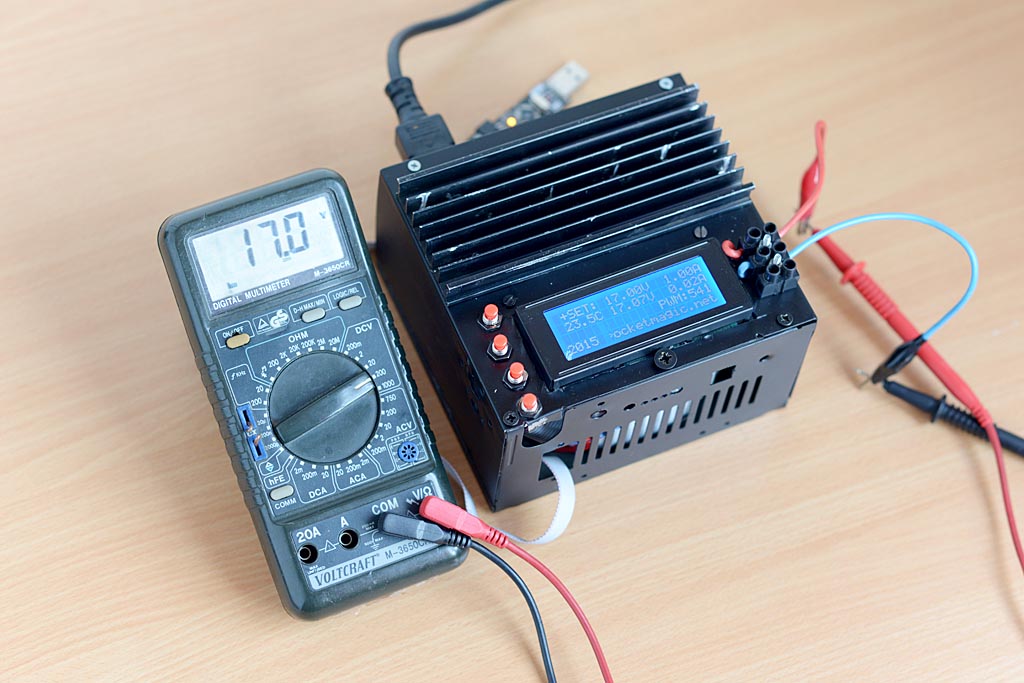
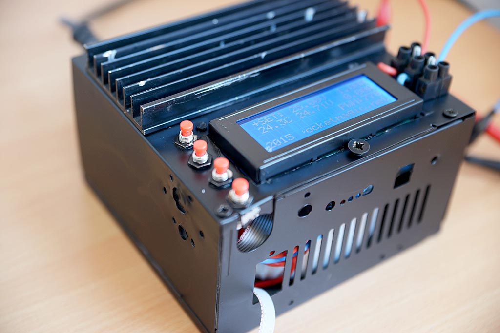
Read more here. You can still find the previous, analogue design below, which is simpler and easier to build:
Variable regulated power supply
Having a variable regulated power supply that can output precise voltages in the 0 .. 30Volts interval is a great add-on for any electronics lab. Especially when it’s a high power supply that can handle as much as 20Amps of current.

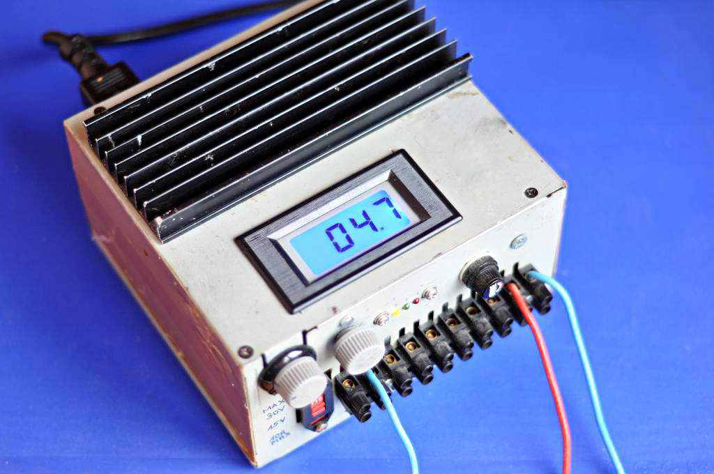
For this article, I’m going to show you my variable regulated power supply, built from scratch, the circuit diagram I’ve used and a few safety tips. It’s based on the LM317 that controls a few high power bipolar transistors connected in parallel, to achieve a 0..30V voltage interval and a maximum current of 20Amps.
Step by step guide
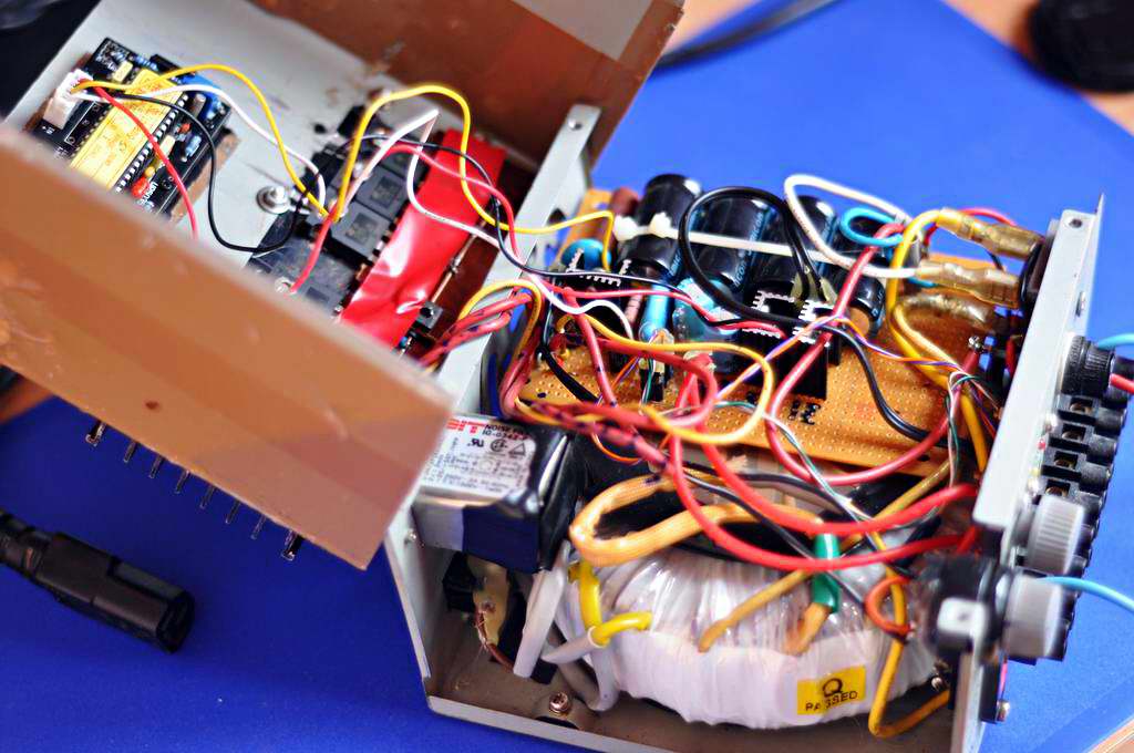
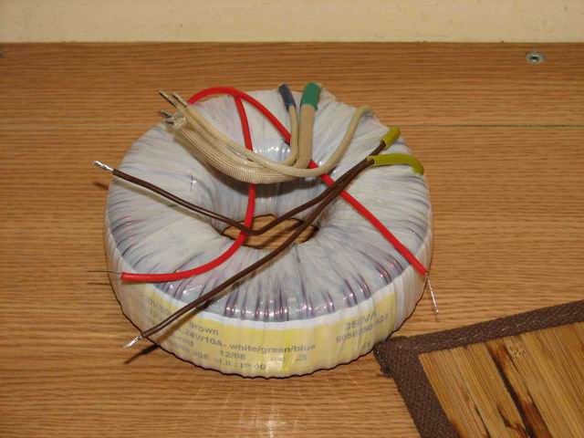
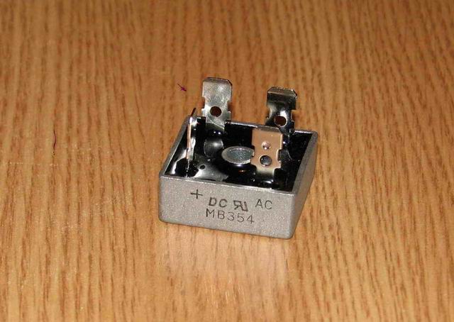
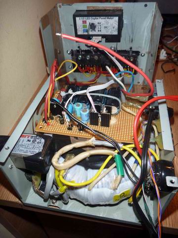
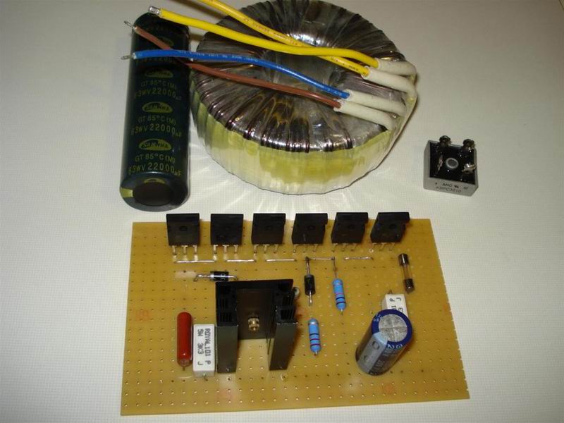
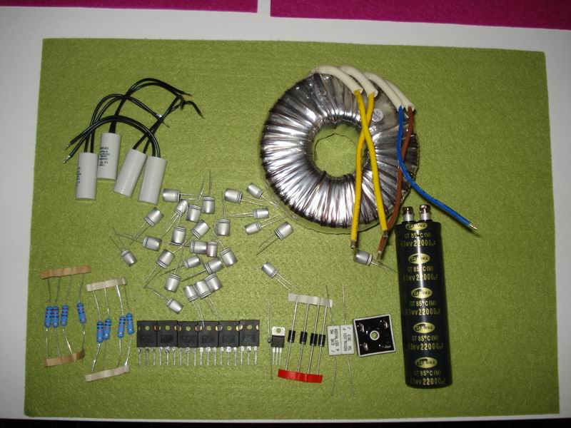
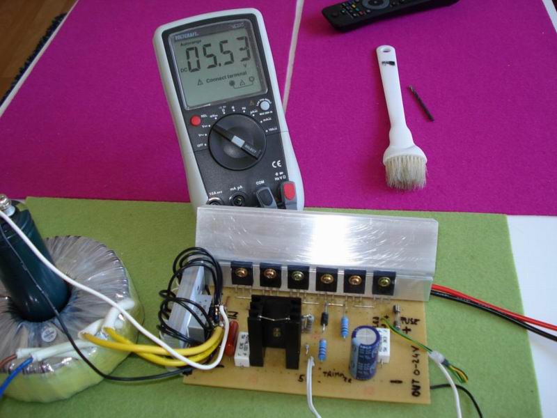
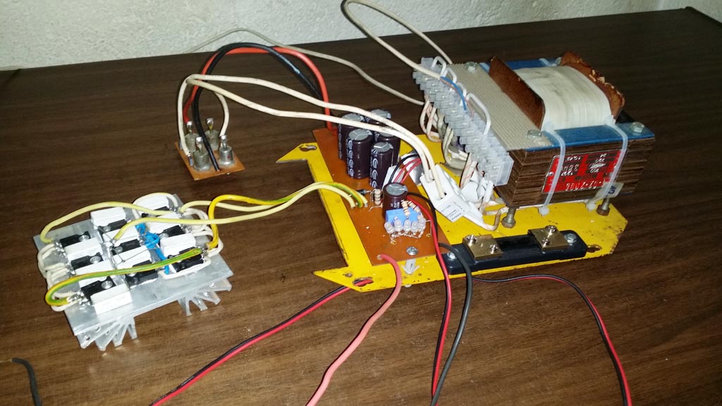
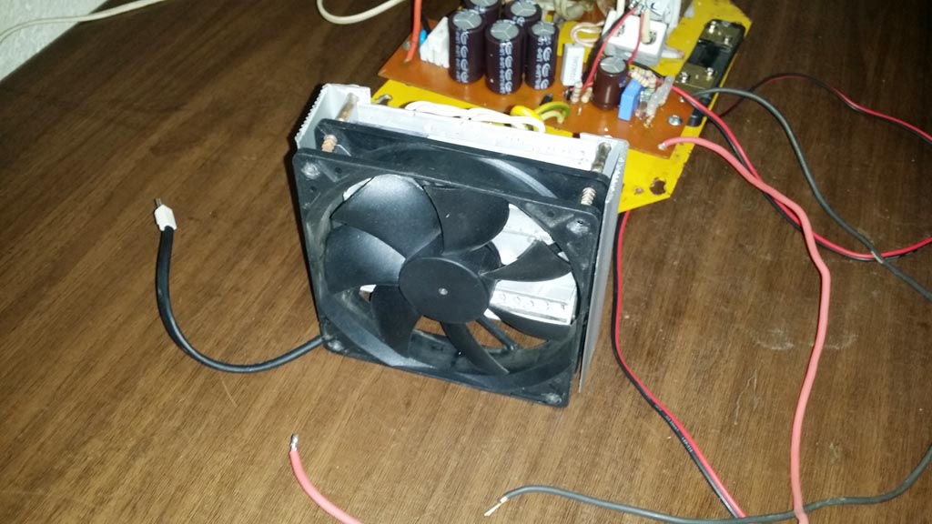
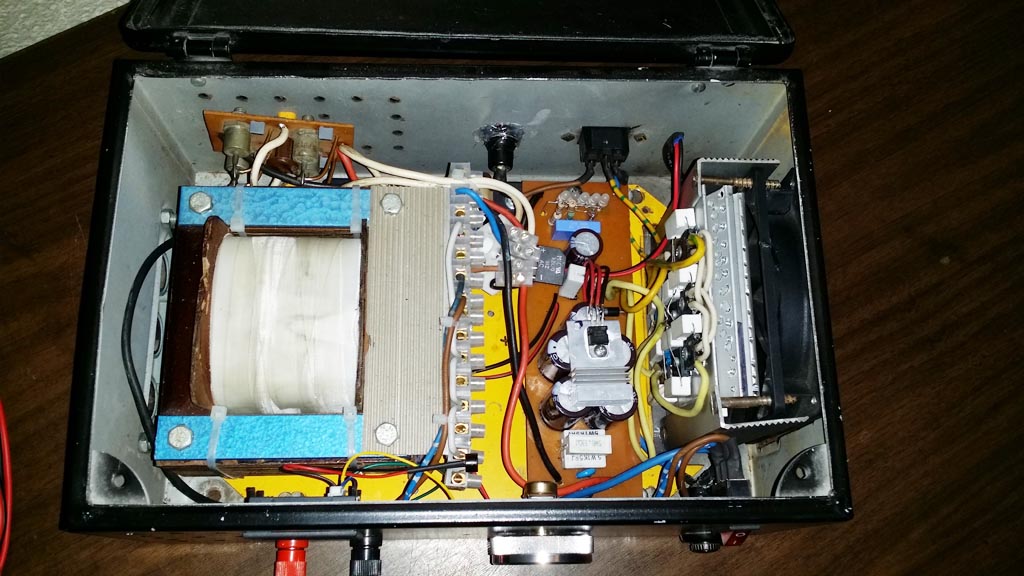
First thing we need is a high power transformer. I’ve ordered a custom toroidal unit, with a primary for 220V mains, and two secondaries one of 24Volts, 10Amps max and another one of 12V, 0.5Amps max. It’s very heavy and it was quite expensive. I also needed a rectifier bridge, and got one capable of handling 400V at 35A max:
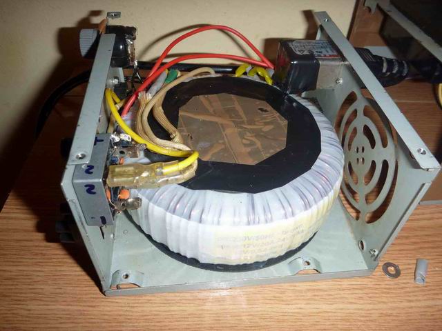
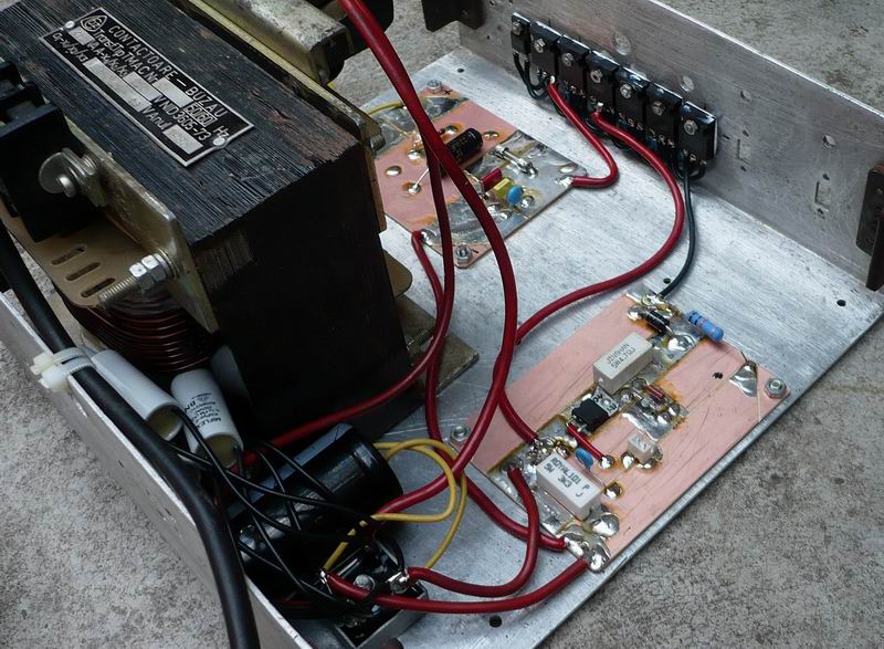
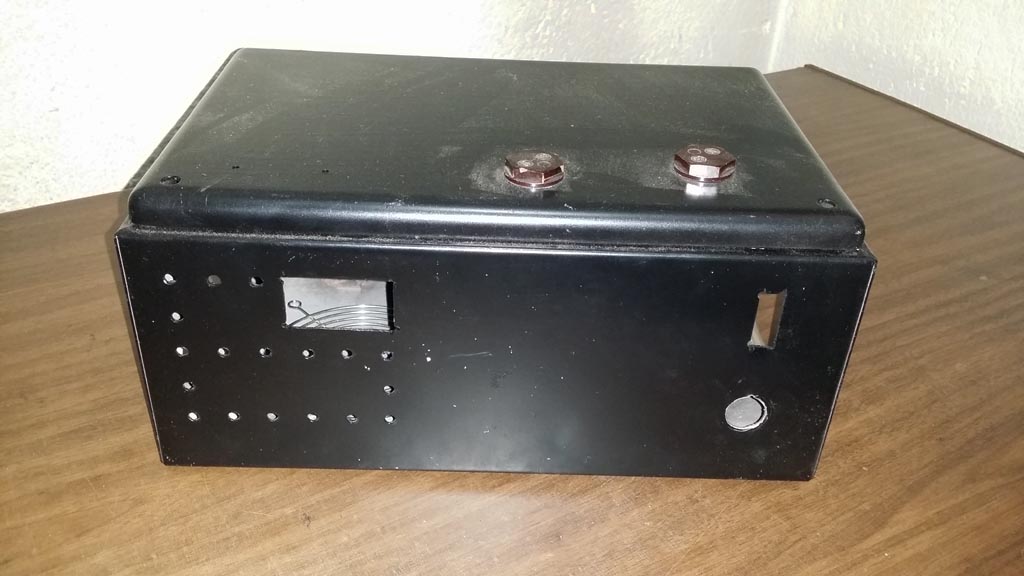
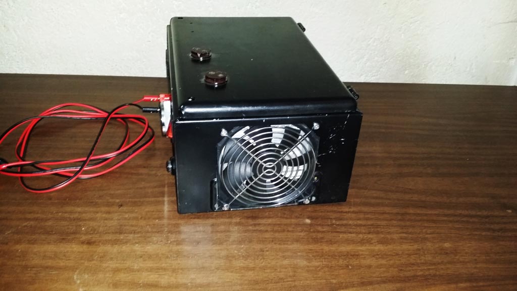
For the project enclosure, I opted for a computer power source metal casing, scrapped from a defective unit: little space but eventually there was enough to fit everything inside and still keep it well organised.
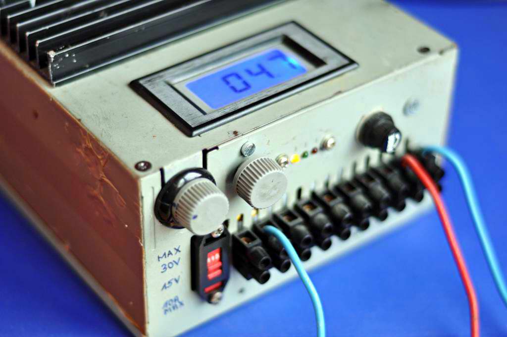
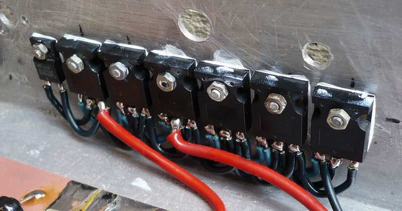
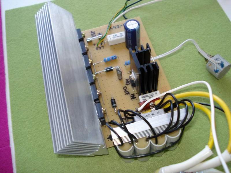
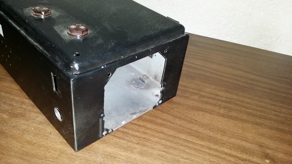
An aluminum heat-sink was added to the case, fixed tightly with several screws so the case itself would also absorb some of the extra heat, for better efficiency. Part of the case was cut so that I could fit a voltmeter and some power transistors directly on the aluminum heatsink:

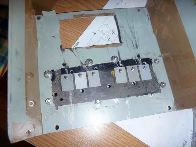
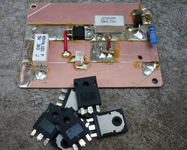
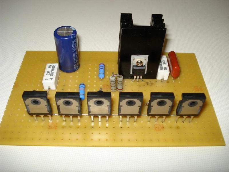
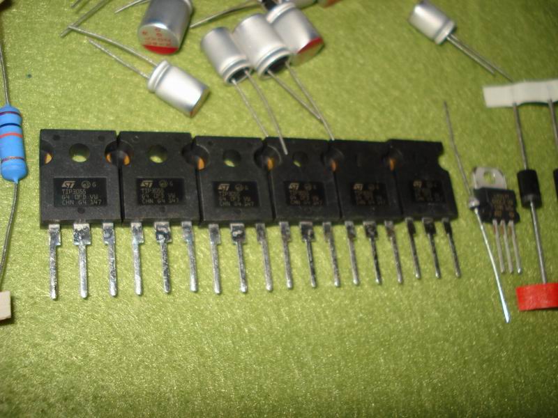
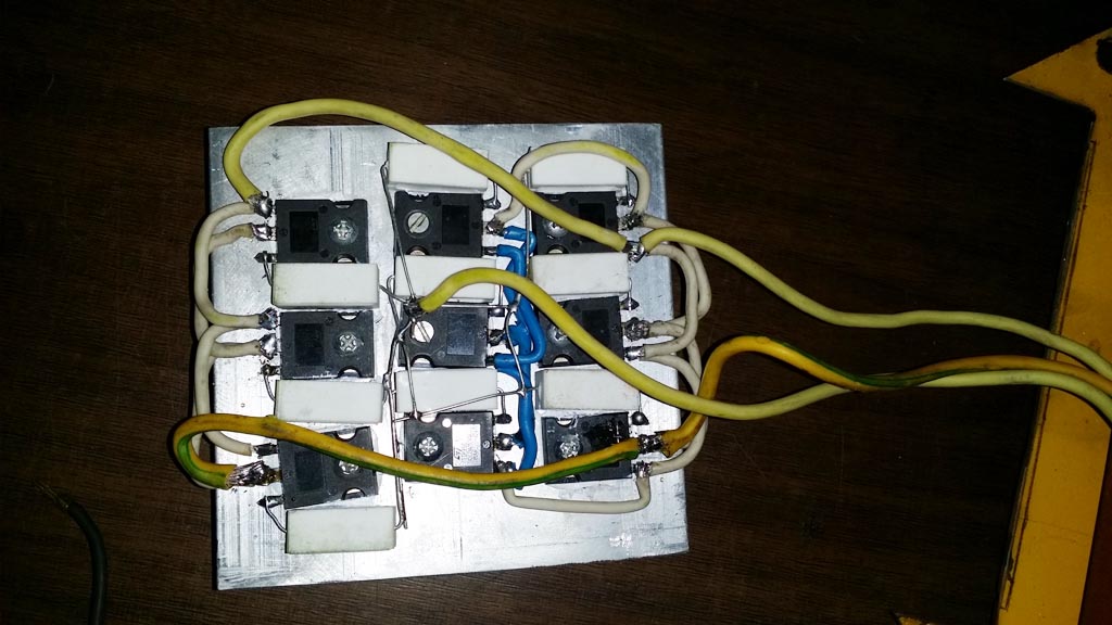
To regulate the output, I’ve decided to use the LM317 to control 6 power transistors (TIP3055 NPN) connected in parallel. The design is illustrated below:
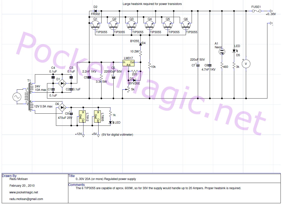
The low power secondary would be used to obtain 12V and 5V with the L7812/L7805, to power the digital voltmeter applied on the high power secondary and also various microcontroller projects that don’t require too much current.
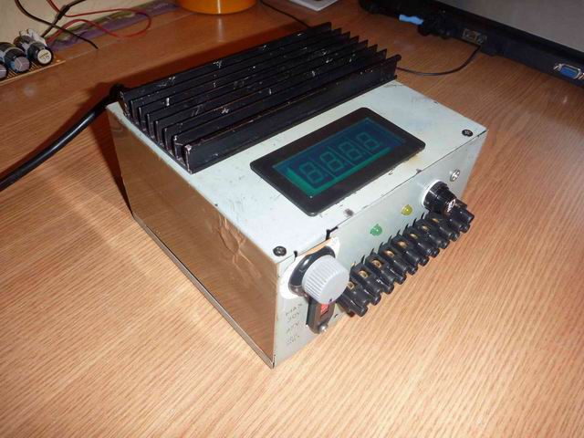
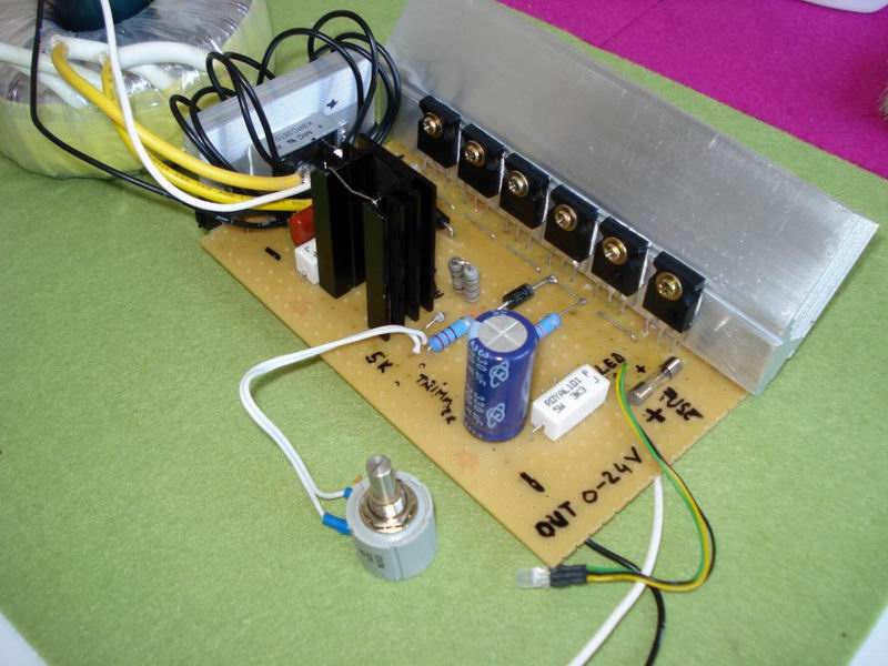
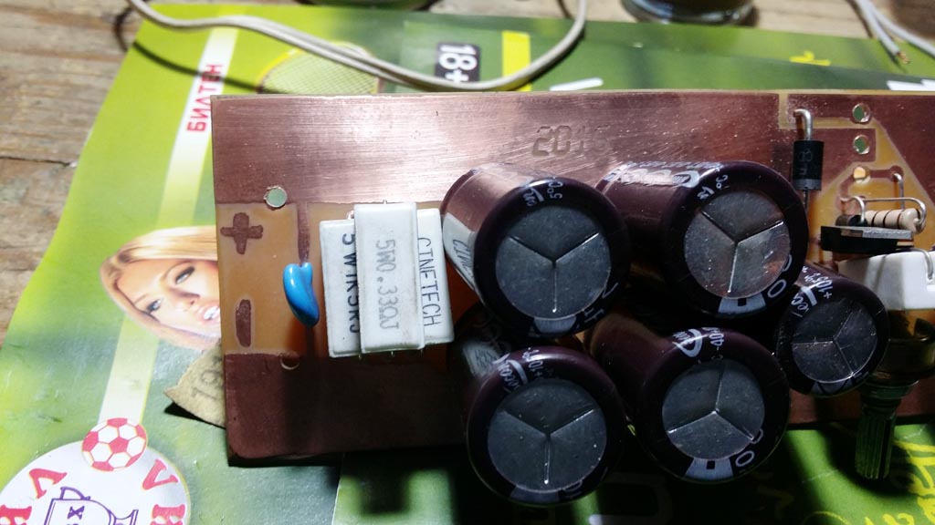
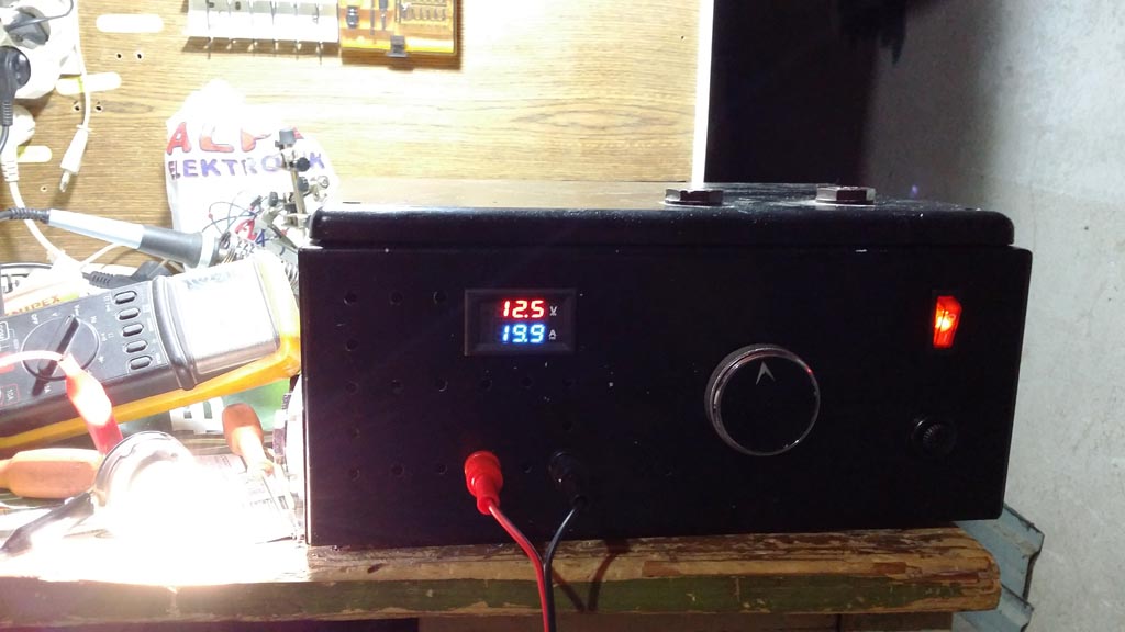
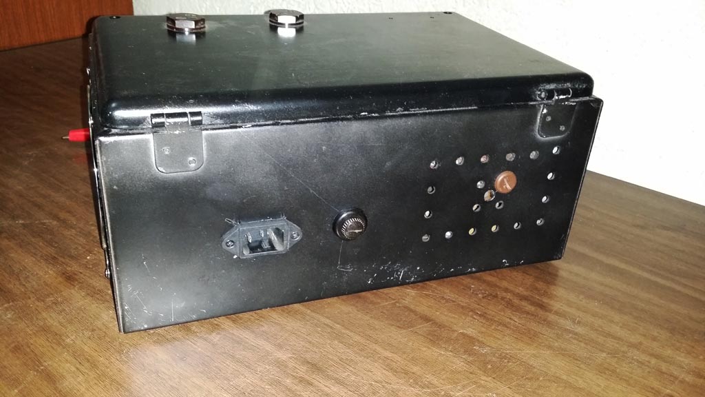
I’ve soldered everything on a test board, using tick copper wire were needed (eg. for the connections to the transistors). A few holes in the front panel and I was able to place the 5k pot for coarse voltage adjustments (and a second 1K pot for fine adjustments, connected in series with the first), the LEDs, the fuse, and the black array of wire connectors for the output (The variable regulated output, the max regulated output, the non rectified alternative current output, the low power 5V and 12V output, etc).
My transformer gives 10A max at 24V, but the regulator block can handle up to 20A max, because of the 6 transistors. I preferred adding a few extra transistors, to distribute the load and help dissipate heat better. If you need more current or less, simply change the number of transistors to suit your needs.
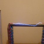
This supply is extremely reliable. I’ve used it for more then a year now, the initial design had 4x 2N3055, but they failed quite frequently because of my high voltage experiments that produced spikes transmitted back to the supply circuit. The TIP3055 seems to be almost indestructible, so I highly recommend it.
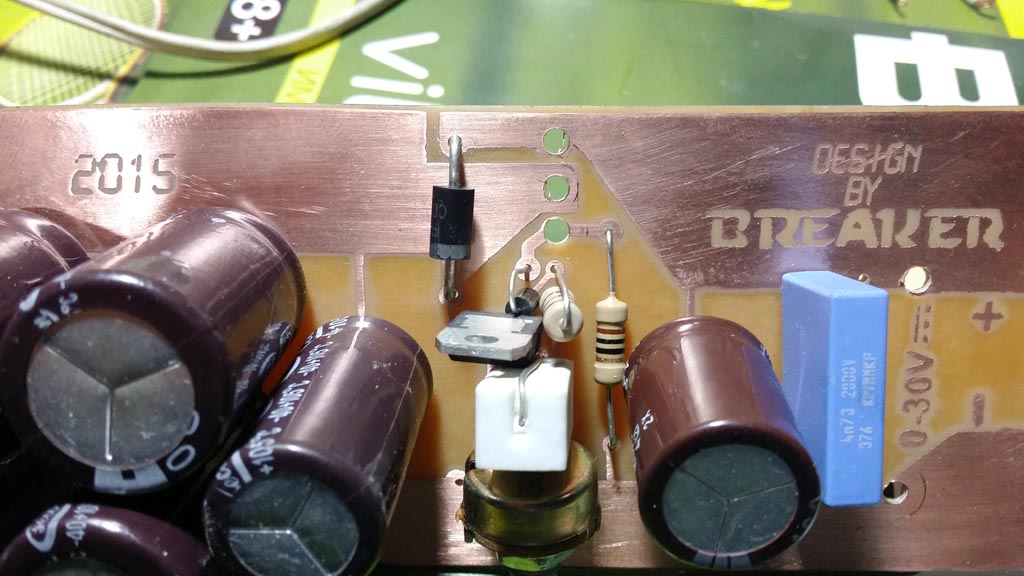
The neon bulb works as a snubber, to protect the supply against high voltage kick backs. I’m not sure you need that if you’re only doing low voltage stuff.
Here are some variants created by my readers


John’s Supply:
As a common effort of several people, this circuit diagram comes with several improvements. You can read the comments below for more details. Instead of the 2n3055 I recommend the TIP3055.

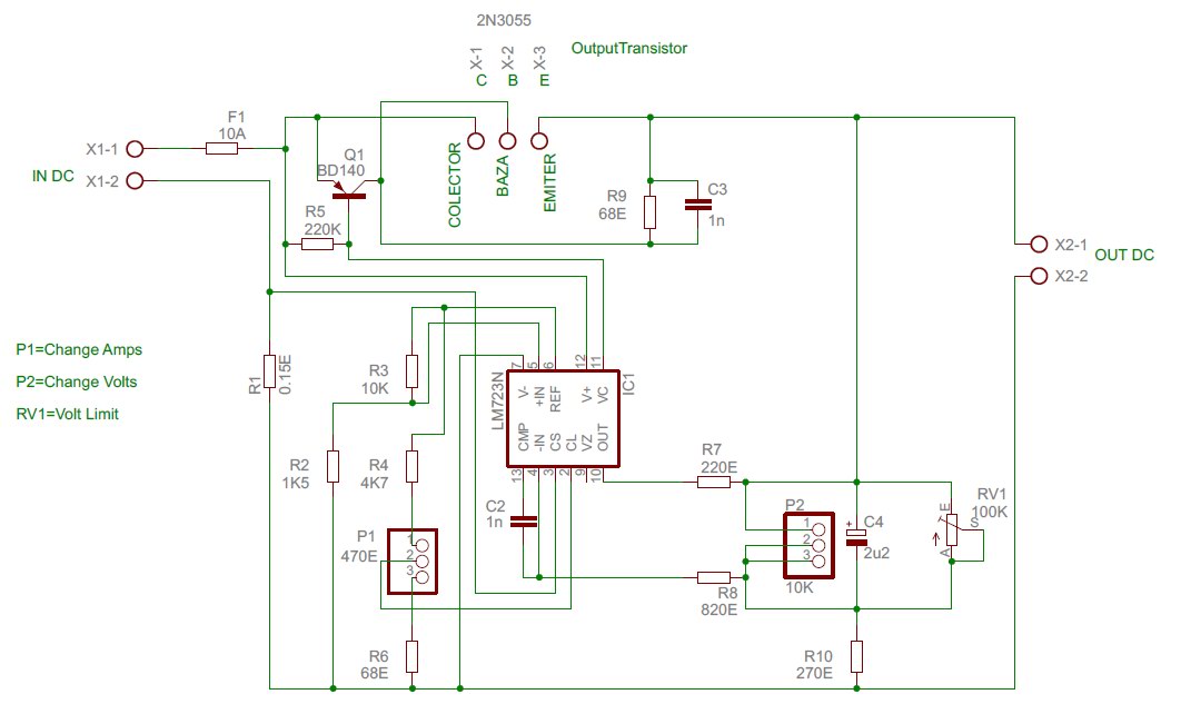
John also provided a regulated power supply that has a nice current control feature, but it uses the LM723 instead:

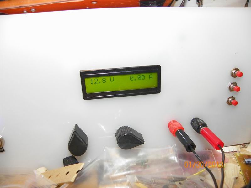
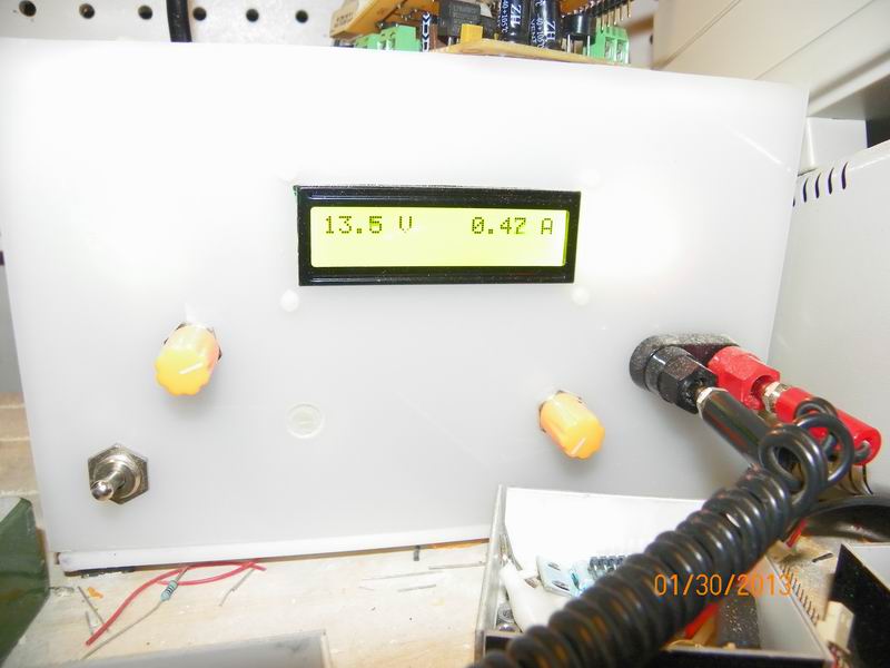
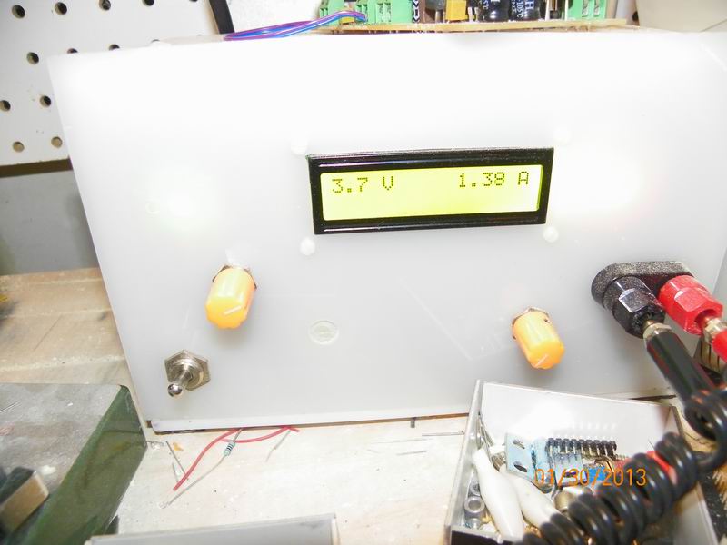
Here is the ready-built supply, using LM723:


Phil’s Supply:
Phil provided several helpful advises (see comments section) for others willing to build a power supply. He also experimented with multiple circuits, seeking for the better alternative.


Vanja’s Supply:
Vanja create a supply with the LM723 , similar to John’s. See it here, including the circuit diagram:
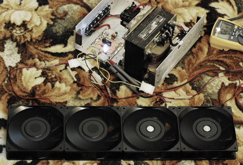
poparamiro’s Supply:
poparamiro built this supply to power a set of fans, to use them in overclocking:
nachtfalke’s Supply:
nachtfalke’s variant also uses a toroidal transformer and 6xTIP3055 power transistors. Again with applications in overclocking, here is yet another nice, clean build:

Stefan’s Supply:
Stefan did an excellent work with his nice construction. Here are a few pics showing his version:


Digital Supply:
As a follow-up to this project, I have upgraded my power supply to a new digital design. Read more here.
For switched power supplies, see this article.

can this power supply be used to charge a car battery with 12Volts 100AH to 120AH rating?
Hi Blade. I suppose it can.
Very nice information, I think it is useful to us. Thanks.
Great!
Super circuit that i still used in my reverse electrochemical oxidation of Gold refining setup & precious metal refining chemistry with slight modification. Thank you. I am an Gold refining chemist. Technical info available gold refinery.
Hi Shahul,
Would love to see some pics of your setup, can you upload them?
Hai Radu Motisan ,Thanks to readout my info. Soon i will upload all the info and pictures .please wait.
Hai Radu Motisan Soon i will upload all the info and pictures .please wait.
i will build your power supply but i can’t undestand where on design those red swich on the back of your supply
hello Borys,
My transformer has a middle tap, so it gives me 0-12-24, I’m using the switch to rectify the 0-12 or the 0-24 output.
ShahulHameed.S, any news?
you don’t draw those switch on the design. where do you put it? can you explane me it better please?
Borys, you don’t need the switch, please forget about it, it was only needed for my particular transformer (because it has two output voltages 12V and 24V so I can select which one to be rectified).
ok i undestand. my last two question
1) where do you found a 22000uF 50V capacitor? it’s a very big and maybe a lot expensive capacitor?
2) On teh design there’s a neon. do i need it? why do you put it there?
anyway thank you for your project, is the best that i found
Hi Borys, I was unable to find a 22000uF capacitor so I used 4x 4700uF/50V capacitors connected in parallel. The price for all 4 was aprox. 6USD.
You would need the neon only to protect the supply from High voltage spikes, I use it for High voltage experiments, but maybe you won’t need it.
ok i undestand. i don’t put those neon but some diodes betweem the voltmeter and the fuse.
Ok. Put some pictures of your setup when it is done, I’m looking forward to see it.
i’ve got a lot a problem because i don’t know where bring some things. today o found a transformer 22oV to 27V in the dump near my town. do you think that it’s ok for this project? i don’t khow how many current it give me because i cannot find it on the web. it called “cecla 38675”. can you try to search it please?
Please measure the Iron Core size, and also put a few pics with the transformer.
http://a.imageshack.us/img834/6713/photo0473i.jpg
here the iron core is 4cm for 8cm
http://a.imageshack.us/img200/9177/photo0472a.jpg
here is 9,5cm for 4cm
http://a.imageshack.us/img594/4406/photo0471f.jpg
and here is 9,5cm for 8cm
can you see the secondary wire? can you guess how tick it is?
this is the primary
http://a.imageshack.us/img192/9343/photo0474o.jpg
this is the secondary
http://a.imageshack.us/img155/8440/photo0475.jpg
you can see the retifier bridge 15A 50v to 1000v
you can read about it here
http://www.alldatasheet.com/datasheet-pdf/pdf/98986/ETC/FB1508L.html
Only a guess, this should give you 10-15 Amps.
anyway i’m goig to return to the dump to find the other components or another transformer. how many languages do you speak? do you now russian, ukrainian or italian?
one question. if your transformer can give you 240VA max how can this power supply give me 600VA?
My transformer only gives 240VA, but the Rectifier+Regulator can handle up to 600VA.
I don’t know Russian, neither Ukrainian, but I know a little Italian.
your power supply give you 600va or 240va? i cannot undestand
again, my transformer only gives 240VA.
In the regulator, I’m using 6 Power transistors, so this block can handle 600VA max.
But the output in my case is 240VA .
can you show me on the design where you connect to have the max dc output and the max ac output please?
Hi Borys, please rephrase, I don’t understand your question. Thanks
you say “and the black array of wire connectors for the output (The variable regulated output, the max regulated output, the non rectified alternative current output,”
i want to know how you can have the max regulated output and the non rectified alternate current.
for example if i want the max regulated output i have to connect two wires betweem the 22000uF capacitor and lm317. am i right?
Yes, you can tap right after the capacitors, and have maximum rectified current.
For alternative current, you can tap before the rectifying bridge.
i need those neon bulb because i will use the royer zvs driver ( i want to build the tesla coil 3)
ok, if you have any questions, ask. you can take the neon bulbs out of voltage control probes (those for 220V, they are very cheap).
tell me something more about those 0,1uF capacitor. show me one datasheet about those capacitor
Hi Borys, C1-C4 are just simple filter capacitors. You can use any 50V 0.1uF cap. But if you want you may exclude them as well. They are not critical for this supply.
what is the diameter of wires that you use there? and of your transformer? because i think that those of 1mmq are too little (my transformer can give me up to 20A) and those of 2mmq are too big because i cannot bend it very well. can i use the 1mmq wires?
I think 1mm is too little. Better use the 2mm (or 2.5mm) and use pliers to nicely pack the wire inside your construction.
If bending is still a problem, consider using stranded wire. It’s easy to find it at any electrics shop.
i will put some more things like an analogic ammeter and analogic voltmeter, two neon bulb and some switch for ac current and max dc current
Sound very promising! Put some pictures here when it’s done, or if you need I can give you an account on this blog to put all the details in a separate post.
but you have to wait because some components i have to get in my school. i think that i wil ent my power supply to the end of october or a bit later because it not very simple to cut the case of atx like i want. i will make a lot of photos and i will post it
ok, Good luck!
Dear Radhu Motisan,
Very Nice Circuit. Thanks.
If my requirment is of only 2 amp. for 0-30v What capacity of transformer should i use. & how much power transistors should i connect. Please advice.
Thanks.
Prashant
Hello Prashant,
You should use a single power transistor TIP3055 instead of the 6 in my design. If overheating is a problem, or if you have a small heatsink, use 2 transistors connected in parallel ,
Regards,
Radu
Hi Radu
what is the name of the programm that you use to draw your design?
Hi Borys, I will check it and get back to you.
Hi Radu!
Here i am! I made it!!!
http://img833.imageshack.us/img833/9605/photo0476.jpg
http://img580.imageshack.us/img580/8907/photo0479.jpg
http://img827.imageshack.us/img827/7863/photo0480r.jpg
http://img207.imageshack.us/img207/8250/photo0481.jpg
http://img810.imageshack.us/img810/8798/photo0482d.jpg
http://img155.imageshack.us/img155/5302/photo0483b.jpg
http://img716.imageshack.us/img716/2089/photo0484v.jpg
http://img214.imageshack.us/img214/8592/photo0485.jpg
http://img833.imageshack.us/img833/8592/photo0485.jpg
http://img830.imageshack.us/img830/8506/photo0486w.jpg
http://img291.imageshack.us/img291/9950/photo0487v.jpg
http://img710.imageshack.us/img710/4631/photo0488k.jpg
My power supply can give me 400w (i’m not sure about it). AC current are 30V 15A, DC max are 40V 12A and variable DC from 1V to 28V not more than 10A because i use the 1mmq wires for it
excellent work Borys! congrats
Thank you! My next project is the royer zvs
Hi I want to build this power supply but I need to have a 0 – 20A current limiter on it
Can any one tel me how to do that?
Thanks
Hi Radu
i’ve burned the second time the tip3055. you’re right about those fuse. you can replace your tip3055 with a tip35c. they are 125W instead 90W of tip3055
Hi Radu, I like your design and simple to follow instructions! I hope you are still answering to this thread, I have been looking around for a 240v input 28v 30A max single output psu design for a while as to buy on is far too expensive, what changes to your design would you recomend for this output?
regards
Phil
Hi Phil, I get email notifications on comments.
I would use at least 8 power transistors in parallel (TIP 3055) on a very large heatsink ( 20cm x 10cm).
pay attention Radu
i made your power supply but do you remember that i’ve used a 230v to 27v?
when i retify everything i’ve got 42v dc max and on the datasheet is wrote that you can use the tip3055 not over 40v. i think if i reduce the capacitor to 4700uF i’ve got 36v dc max. i am right?
Hello, your article has been very helpful, however could I substitute the transformer with a PC power supply that outputs 12v? What about one that outputs 5v? Assuming that both have enough current capacity.
Thank you Radu, just had a look at my redundant spare zetagi 13.8v 25a radio psu based on 5 old 2N3053 mounted on a massive heat sink at the rear, its not a great psu but it can be internaly regulated up to +26.5v and has a very large iron core giving +28.6v at the bridge rec.
Another bonus is the case is pre cut under a plastic front cover for a front fuse holder, meter and variable pot. so half way threre already.
Found a cheap oputlet for surplus stock TIP 35c so may try your build with 6 of these instead of 8 TIP 3055
Any thoughts?
regards
Phil
Hi Phil, that’s great, feel free to post some pictures when you get the chance!
You can use any set of high-power bipolar transistors for this supply, with small variations in the output based on transistor model.
TIP35C should be fine.
Initially I was using 4x 2n3055 but because I was powering some high voltage inverters with voltage spikes, the transistors were failing very often. 6xTIP3055 seem to do a better job.
Cheers Radu, this is for radio use when testing a 28-30v 250W HF/VHF commercial and military grade home brew linear amplifier. The plan is to use whats available and keep the cost down as I am disabled and not working at the moment, It would be a tight squeeze to fit 8 TIP3055 on the heatsink but 6 TIP35c will fit ok.
Ive got the parts shopping list together and its looking good, there are some nice combo volt/amp digital panel meters available on the internet now but the price is a little too high for my pocket although I do like the idea of a current reading at the touch of a button, I will photograph the build stages as I advance but it will be a slow build due to my circumstances lol.
regards
Phil
Hi again Radu, a couple of parts specific questions if you dont mind,
Caps.
4 x C1 to C4 on bridge rec. 0.1uF are these standard disc ceramic and what voltage rating recomended?
Specific resistor info please.
1 X 220 ohm res on adjust of LM317 is this 1/4w 1w 2w or higher?
1 x 10k res from base of power transistors 1/4w or higher also the LED and neon res?
Do either the 10 ohm 2W res on the LM317 output or the 10K res on the TIP3055 base have to be metal film or is wirewound ok.
regards
Phil
Hi Phil, thanks for the follow-up,
C1-C4 are standard ceramic caps, the voltage can be twice the max voltage outputted by the transformer,
all the resistors can be 1/4W unless otherwise specified, eg. there is that 2W resistor.
The LED can be any led, there is no tight requirement here, the neon you will probably not need it, I sometimes use my supply with high voltage inverters that can kick back with voltage spikes, that’s why I used the neon. But for general use, you can skip it.
The 2W 10Ohm can be either type, since this is a DC circuit. For any other questions, I’m happy to help, just post them here!
Good luck, and have a better New Year!
Help, the diodes listed seem to be only available as bulk purchases
(£20 minimum purchase!) here in the UK
BYV26E
BY255
FR302
also not for psu
BY133 (x2 needed for a repair)
Anybody know of any general use easy purchase alternatives please?
regards
Phil
Phil, you can go for 1n4007’s (D2,D3,D4).
Hallo, nice works! I want to realize this amazing project,however with less power.
-How much TIP3055 must I use if I need only 4A?
-How much current add every TIP3055?
-Can you suggest me any D2 (FR302) Equivalent?
Best regards
Hello Heinrich, use 1n4007 instead of D2. It will work.
Regarding the current, what are the parameters of your transformer?
For 4A, you could use 2x(two) TIP3055. Hope this helps.
Thanks for quick response.
My transformer is a 120VA with 2x15V output.
So,every TIP3055 add circa 3A of maximal output current?
According to the datasheet: http://www.datasheetcatalog.org/datasheet/stmicroelectronics/4136.pdf
TIP3055 can dissipate 90W up to 25°C, and a lot less after this threshold. It can withstand a collector current of 15A max.
For 30V, one TIP3055 should be able to handle 3A (30V * 3A = 90W) IF A GOOD HEATSINK is provided!
For 15V, one can take as high as 6A, again, with a big heatsink.
To minimize the thermal stress, and to require a smaller heatsink, you should use two (or more) in parallel. By doing so, each TIP3055 will take a proportional part of the current and the heating produced will be smaller (safer for the components).
Hey Radu
I have some questions. How much is your max dc and ac voltage? Up to now i have broken 2 tip3055 because my max dc was 42v. I have red on the datasheet that the max voltage collector emitter musn’t be more than 40v. Did you ever broke one transistor? Have you got any idea?
@Borys, my AC is 24V . The rectified DC goes up to 32V. I’m using TIP3055.
A while ago when I was using 2n3055, and doing high voltage inverters, powered with this supply, I sometimes got burned transistors because of over volted spikes. Since then , using TIP3055 , no transistor was burned.
Note that note all the 2n3055’s are the same, some of them have a last letter identifier, and the ratings are different.
thank you for your quick answer. now i retry to remake everything but now i modify my transformet and i have 24ac instead of 29ac but when i retify i have 35v instead of 32v. i think that is not a big problem for tip3055.
it should be fine
Hi Radu
i remake for the third time my power supply but for the third time i have burned one of 6 transistor. my dc max is 32,7v. maybe i stelled bad they or the temperature of my welder is too high.have you got any idea or any substitute for tip3055?
Borys, sorry to hear that, can you post more details like what exactly you did when the transistor burned?
For a substitute you should look at other high power NPN bipolar transistors.
Hi Radu!
I have checked my power supply and i have burned the lm317 not the transistor. I dont know why. When i tested my supply i have used the 2n3055 push pull flyback driver at 15v and maybe 3a ( max current is 5A) and after half minute the lm317 ( paid) is broke down. When i remake the supply i replace the old lm317 ( found in the dump ) with a new one
Super awesome-riffic !
I’ve bought a big torodial transformer and I’m going to attempt to build this supply.
Can you say anything about how hard it is to build this PSU ? (You know easy , medium or hard ?)
@Lukas: very easy! also you can ask questions here, and me or other can help you.
@Borys, sorry didn’t see your comment before. It happened to me to burn the LM317 once as well. How is it working now?
yes its very easy to make
Hi Radu, here is an update on my build, I was having lots of problems getting this to work after building so I dismantled and started again only to find I have been supplied with a LM3171 instead of a LM317 I hope no other damage has been caused to other components, this only goes to show never trust suppliers and always double check all components before construction, oh well starting again.
PS. the combination volts/amps digital meter I purchased from china fits the case perfect and works lovely but the current shunt to handle 30A is quite big and took a lot of work to fit to the power board but it does look good.
Phil
Hi Phil, that’s great. I’d love to see your setup when it’s done and maybe to include your own version in the article above.
May I ask what type to volts/amps meter did you get? Can you post a link?
Thanks,
Radu
your wish is my command try this on ebay
Item number: 260633169349 from seller Lightning Boy USA
HINT! ask him nicely and he will ship reduced declared value so not to get stung by customs and import duty, worked for me folks.
Found it, thanks!
It looks like the same size with what I’ve used, so I guess its time for an upgrade 🙂
can i use your schematic and post it on another site? i will tell them where i bring it. only if you’re right
Sure, Borys, You can post it.
Well three times I have blown the LM317 at switch on! I think the 29.8V supply must be surging over 30V when switching on, getting perfect 29.8V but no regulated adjustment so may have to try an alternative setup with a 2N2222 on the adjust and a relay switch on the feed in, I have also read that D3 should be replaced with a IN4148 and D4 replaced with IN4001 when higher voltages are pressent? oh well back to the drawing board.
Hi Phil
Wont it work if you use the LM317hvt it has got a limit of 45V my power supply is regulated 42V in and have not ones blown the Lm317hvt
I will give it a try thanks Charl.
After rectifier bridge and filter capacitors , I get 32V DC . The LM317 works fine, but as Charl said, maybe you’re using some LM317 variant that can’t handle this much.
yes yuo’re right Radu. the lm317t work fine. last time i have burned another tip3055. maybe my transistor are some variant of your. anyway when i can i will try to replace them with tip35c
Possible, let me know if the tip35C works better. I got my tip3055 from ebay, seller thaishopetc (he sells good quality components).
The new LM317t that failed was a good quality one from a trusted suplier so I wonder if the problem could be the four old radial 4700uF/50v filter caps salvaged from the old psu I gutted for the case, trying to save money might not be a good idea after all, Ive seen lots of good deals for new small profile 4700uF/50v caps on ebay so I might replace them with a bunch of new ones (5 or even sometimes 7 x 4700uF/50v recomended for to filter a 30v radio psu, seems a bit overkill to me?)
Hi Radu,
I have a hacked computer SMPS that gives out 12V@25A and 5V@40A.
I was just thinking that can your circuit be used to get variable voltage upto 12V@25A?
If yes then please suggest any modifications to the above circuit that can work for my setup.
And one more query,the fast diodes used in your circuit are not available at my location,only one fast diode called BA157 and other common diodes like 1N4005,1N4148 and 1N5408 are available.Which one of them will work for D2,D3 and D4.
I will be using this to power my ZVS driver and plasma speaker.
And few more queries:
Will there be a need for 22000uf/50v cap. for my setup i.e for SMPS based supply,I mean that cap is being used for filtering(right?)while using transformer based supply.And if my setup do need it,will 4x 4700uf/35v cap bank work?
And why C5 and C8 rated for 1KV.Are they there to absorb high voltage spikes from high voltage circuits you use(I will also be using this supply for the same applications).
How many transistors(TIP3055)will be needed for my setup?
Any other suggestions to protect my SMPS from back spikes generated while using zvs drivers and other high voltage drivers(I have already blown up my 2 SMPS(hacked ones),dont want to blow up this one).
Abhishek, the diodes are not critical, feel free to replace them with what you find, just try to match the parameters as close as possible.
You won’t be needing the filtering cap,since you are using the SMPS supply.
The high voltage caps are filters/spike absorbers, you should use them.
If I remember correctly,one TIP3055 can dissipate 90W so to regulate the output from 0 to 12V@25A max, you’ll need 4 transistors and proper heatsink. To reduce the thermal stress / transistor you can use 6 like I did.
Looking forward to your complete setup, send me some pictures when it’s done.
Thanks for the quick response.
I am on my way to make it as soon as possible(fight going on with my semester exams :)).
Will surely send you some pics of my setup.
Thanks once again.
One of my friend suggested that there should be a resistor in series with each collector of the transistor,otherwise they would blow up.
Is this true?
Indeed it is advisable to add resistors , not on the collectors but on the emitters (0.4- 1Ohm). For me it worked fine even without those.
one question,what does the VA rating of a transformer indicates? Is VA equals the raw power available by the relation i.e Power=Voltage(V) x Current(I).In short,Is the VA rating of a transformer same as Voltage of the transformer multiplied by its current.
mine is a 250VA:
secondary 1: 24V 10A max with a median tap for 12V
secondary 2: 12V 0.5A
Hi Radu
finally it’s work fine. i have used 5x tip35c and they are ok. one of those transistor can dissipate 125watts, very good. i have the same transformer that don’t give me 15A, but only 6A. not bad. you forget that to calculate the dissipation you have to do this:
(Vin-Vout)/I where Vin is the voltage of collector and Vout is the voltage of emitter and the current that you use
@Borys, yes that is almost correct, the dissipation is in watts so it is:
(Vin – Vout) * I
I indicated the dissipation for worse case scenario: Vout = 0 .
What are you working on?
ah ok
now i’m doing an audio amplifier and i want to make the royer driver
Completed my variable power supply,Thanks for the useful info you provided.
Sending you pics of my supply in a minute.
that’s great Abhishek, looking forward to seeing it!
Hi Radu,
Is this supply short cicuit protected?
no, but you can add a short circuit protection easily. I will write another tutorial for that
Let me know about that mate.
D1 si D6 cel mode sunt? sau ce parametri au?
Radu,
The transistors need emitter resistors to force current sharing (0,1-0,22 ohms each). Otherwise, the transistor with the highest beta (and lowest b-e voltage) will do all the work, become hotter, and fail.
Secondly, you can considerably improve the regulation if you put the one end of the 220R resistor not to the LM output but to the emitters of the transistors (after the emitter resistors that is).
Regards
Martin
what martin says is very true
you do need some current sharing
one other thing you can do is drive one NPN
then have it drive the transistors array in a BE follower type setup this will take almost all the load off the LM317
and you will get more out of your 3055’s it takes a lot to get them on 100%
the TIP3055 take a little less to get to that 100% that’s why you burned up your other 2n3055’s
doing BE follower and adding a 0.05ohm 2watt on the output of each TIP3055 will fix 95% of all your burn up problems
adding a 1~10ohm 1/2~1watt to the base will help with overdrive of the TIP3055’s when 40~45V input is used
i have a 170 amp ver of a power supply with the mods i stated running strong over 2 years
4 transformers feed 24F cap bank then feed transistors array witch charge a 10F cap to output. it’s 2.5~28v 135~170amp 240 amp 2sec surge 500 amp 1/2sec surge
2N3055 peek at 28C at 200amp load at 13.8v after 15 mins never pass 25c 180amps load at 13.8v
built relays and temp probes cut main power if any heat sink hits 45c (it’s only happen once and it was a 32c day and a 234amp static load)
my transformers after my 50amp rectifiers each output 32v and each one is about the size of a basketball and is rated for 120amps EACH
i have a front panel power switch for each transformer
has 3 input cords as well 120v input
transformers are from welding gear same with rectifiers
i build /rebuild competition car audio amplifiers some put out will over 10,000 watts continuous and run anywhere from 12 to 20 V I have six 16,000 watt amps in my setup.
FYI 2 transformers are 220amp out 240V in the other 2 are 120amp 120v
i have a single 240v 35amp plug and 2 15amp 120v plugs
i have 2 RV hookups with 240v 40amp lines i plug in to for running big stuff
other wise i only use 1 or 2 120v plug
if i push 16~28v (i have to change a jumper)
i can boost output amperage by 25%+
i have a 100F cap bank i add to it when i do this
all my caps are rated for 36v working 50v surge (high side caps have a 50v working 72v surge rating)
i will post links to pic’s sometime when i feel like it
Thanks to all for all of your information.
Hi
Will this power supply run a 24v 15a screw drive for a gate opner as my power supply puts out 31vdc at 20+ amps
I believe it would work. You will need a big heatsink for the transistors, and see Martin’s and Joe’s suggestions above.
Hi Radu
I need to know what wattage size for the emiter resistors that
martin used.
I also fired up my transformer last night and get 32v dc at the 63000uf 50v cap.
I want to use tip35c transistors and could you please explain
how to make one transistor drive the others.
Hi Radu
Do U perhaps know how I can make a current limiter for this power supply because some times I don’t want to push 30A trough a circuit
Thanks
G’day mate, nice design and very well written article you’ve got here.
I’ve got just one question with regard to the number of 3055’s.
I plan to use this circuit on a 20.5 + 20.5 dual secondary XFMR that’s good for 30 amps per secondary and my question is, do you need to change the value of the base drive resistor (between the 317 and the base’s) depending on how many transistors are needed?
Jim, I’m not aware of any such change. Initially I used this circuit with only 4 transistors and moved to 6 without any change on the resistor you’ve mentioned.
sweet, thanks for the prompt reply.
I’ll give it a bash with 16 x 2n3055’s
If all goes well, I’ll post the results in a couple of months.
Thanks,
Jim.
can i use 2n 3055 in place of tip 3055
yes, you can.
Where did you get this heat sink? It looks dirt&cheap, exactly the kind I want for my projets.
what is its input voltage?
Can this be connected to a 220V-outlet?
No. This is for low voltage only.
input voltage is based on the Transformer(s) used
i see no reason this can’t be made to use on 220~240 if you have the Right Transformers
just make sure you don’t send to high a voltage to the 317 and you be fine
i just built a new small bench top psu with 3 low ripple outputs(under 10mv ripple) each 10A
and each 2.5v~18.4V using all SMD parts and it’s not much bigger then a ATX PSU
the the custom 3 tap toroidal is in a separate Fined case under the bench
@TechMasterJoe, I wouldn’t encourage him to go for 220V. If he asked this question, it is almost certain he would plug the circuit directly to mains voltage, without doing the proper modifications.
a quick look at dazy npn
http://techmasterjoe.com/made/dazynpn.jpg
values must be changed to match what your looking for
but this will give you a head start
that photo is in eagle and that sch
i can expect 15amps constant with avg heat sinking
Q7 can be a TO220 case it only has about a 2A load if driving <3 2nd stage npn's
if you add a 2nd to Q6 you can drive about up to 12 mosfets in the finale stage
you get less heating in the mosfet's this way do to higher base current
aka more latching power but you still need good heat sinking
if using more then 3 in 2nd stage use a TO3A case mosfet for the first stage
with
1 to220 1st stage feeding dual TO3 2nd stage and 8 TO3 3rd stage
with a 24v in and 13.8v out you can support 40A without mosfet's getting past 28c
with rated heatsinks this is about the size of a shoe box when built the control borad is about the size of a business card with the first stage on board and can be used solo as a 3~5amp Vreg
Is that a 3.3MOhm 5W resistor? Is there a higher resolution schematic available? Is there a complete parts list available other than the schematic?
Thank you.
Jim
Hey Jim,
I’ve re-uploaded the higher res version, just click on the schematic to get the new file. If needed do a page refresh.
i want to use this power supply for 1A vareing from 3v to 12v for use of 1w led in parrell&seriel.whether power transistors are neccessery aslm317 can use up to 5A .wether the can be used as a current limitting one as led requires constant power supply constant voltage.here voltage is regulated .for current regulation i have to do?
hi! i made this power supply but i have a problem. when i put a any resistor the first tip3055 is getting to hot and then it burned.why this happen? any advise?
Hi…. this is briliant project,
I want to build this power supply but I want to have a 0-20A current adjustable (current control)and current limiter for short-circuit (PSU safety) on it
Can any one tell me,
How to do that?
Thanks
hi;
its really a very nice project. can you please explain the operation of the Transistors here? and why 2n3055 blown off frequently? also explain the use of neon bulb a bit more? secondly can i connect 4 LM338 parallel to get 20A at output.
hope you will answer me
thank u
Hi,
I am planning to build this power supply soon, as it seems to be a great design achieving both simplicity and high output power.
I want to take into consideration Martin’s advice of adding emitter resistors of 0.1-0.2 ohms to force current sharing, and connecting the 220R resistor to the emitters.
How many watts should the emitter resistors be?
And the other end of the 220R resistor should be connected just before the fuse so as to be connected to all the emitters as well, then?
Oh and if I understood correctly, TIP35C can be used instead of TIP3055 without any changes in the circuit?
Thank you all very much, this is a very smart thread.
Lucas
I want to take into consideration Martin’s advice of adding emitter resistors of 0.1-0.2 ohms to force current sharing, and connecting the 220R resistor to the emitters. How many watts should the emitter resistors be?
——
This is only my guess, but I think its going something like this:
P = Vd*I
Vd = R*I
Vd-voltage drop across resistor
so..
P = R*I^2
so lets say we can have maximmum of 5A running through each resistor…
P = 0.1Ohm*(5A)^2 = 2.5Watts
So, you will need at least 2.5Watts resistor, but it will get hot, so better to use like 3-5 Watts..
I think that the one in this page show how it is connected: http://ludens.cl/Electron/Ps20/Ps20.html
I also think that this construction is much better than the one shown above. For instance it have all the transistors outputs grounded, this is especially good if you use transistors in TO3 case, because it completelly dismiss the use of insulators between the transistors TO3 case and heatskink thus greatly improves(lowers) thermal resistance(between the transistor case and heatskink).
—————
Oh and if I understood correctly, TIP35C can be used instead of TIP3055 without any changes in the circuit?
—————-
Yes. You can use whatever you like, but keep in mind, that you must still pay attention to the things like hfe gain, thermal junction-case resistance, power dissipation, etc..
This page is also quite handfull: http://ludens.cl/Electron/Thermal.html
first find the peek load each transistor can take and the voltage you are most likely to be running
for me it was 12v at apx 10amps each PEEK SO
(V*I)* R = resistors wattage this is a basic guide + – 15% is fine
(this is very basic and learning ohms law is a must before anyone try things like this)
i use 0.05ohm 8 watt and have never had any transistors fail. even when over loaded by 50% (that’s over 400amps output from my setup lol)
any 1/8-1/4watt resistors will work for feedback control
Tip35c will work just fine
“And the other end of the 220R resistor should be connected just before the fuse so as to be connected to all the emitters as well”
yes it needs to be on your output right after all the transistors current sharing resistors..
add about 1000mcf+ for each amp you plain to drive on your output this is to filter the switching noise out it will slow voltage change a bit when little to no load is on.
i think a 3watt static load resistor is a good idea to help stabilize the output
I used 5 x 5w 0.1 Ohm resistors on the emitters of the 5 x TIP3055 on my first build which ended up with 6 TIP3055 with the first one feeding the other 5 in a BE follower style which managed 28v 27A and after a while I did burn up one resitor, the six transisors are on two separate heatsinks with not a lot of room behind for the large resistors to get air to cool, when I rebuilt I noticed that on the old Zetagi psu TIP3055 back circuit boards (which was the base and case for my psu build)that the emitters from the old power transistors were linked with coiled stiff wire bridges and I decided to put the meter over one of them low and behold 0.1 Ohm! these were black and had seen lots of heat but still bang on so after lots of trawling through the junk box I managed to find some similar wire (paper clips) that when wound to the same design (3 turns around a 4mm drill bit) I got exactly 0.1 Ohm, these have been working fine now for about 12 weeks on a heavy duty cycle with the 6 TIP3055 layed out as per Radu’s diagram NOT a BE follower as my previous build.
Please note as my power requirements are not as high as they were when I first built this PSU I have now change the value of the variable reistor so the max output of the psu the never goes above 19.8V as I found that once it reached 25v and above the stability was very hit and miss but 20v and under it is stable to within about 0.25v (I am working on this to achieve better)
Keep building folks but please be safe.
can TIPs be replaced with ST13009 High voltage fast-switching
NPN power transistors? 220 Ohm resistor and 5k potentiometer smoked in my circuit, what can be the problem?
Hi
I have a question what modifications must be made in order to use a 60 volts/10 amps transformer insetead this transformer and extend the supply to 0-60 v?
Hi brother. I have made your power supply but i am having some problems in it. Voltage is shown on output something around 23.2 and it is not regulating. 2 hours before it was fine but then my 220 resistor burned up and now voltage is not regulating with the pot. i have changed LM317 and the pot but all in vain. Can you plz help me.
and i want to ask you that my transformer is of 36V and 325VA. So how much current will it give???
no correct answer specifically for my question.my i request for the correct answer please?
winner23: First you choose the regulator, which will give you regulation to ~60V, for instance this one: http://www.farnell.com/datasheets/316192.pdf
Second, all the capacitors must be rated at +60V. If you look at sychematic, capacitors C3, C7, this two must be rated at 60V, probably its better to stick to 100V so you have a margin..
Also the transistors must be rated to +60V, probably more. Because TIP3055 is already rated at 100V, thats not a problem, so you can stick to TIP3055…
Please look at this helpfull site: http://ludens.cl/Electron/Thermal.html to determine, how many transistor you must use in your case.
afaik, no other components have to be changed. For last have also a look, at the regulator datasheet, to determine its gain/resistance cue..
Radu, Thanks for sharing this design. As others have remarked, it is the best I’ve seen on the Internet. It’s particularly appealing to me after reading that you previously had trouble with high voltage spikes. I’m looking to build a new unit because I ruined the last with high voltage spikes.
One question that I’d like to ask you is why you chose to use a toroidal transformer, instead of something more common that would have been inexpensive or maybe free?
Thanks,
JG
Hi Jerry,
I only used a toroidal because that’s what a company I had access to was producing at that time.
Feel free to use any other transformer of your choice.
hi dear,
how are you?
please help me for make a power supply 0-30v and 0-5A output
thank you.
@ omid and others reading
Please note to make this PSU you must first of all have a tranformer primary rated for your domestic votage supply that will also give you enough volts and amps secondary output for the DC supply you require, for example here I use a 240v primary AC volts input with an output of just under 30V before any smoothing or rectificaton to DC, it is a very large old heavy core transformer and gives as stable smooth DC output of 0-26V and 25A once rectified so dont expect small discarded (junk) transformers to perform miracles.
Also if you have problems with the voltage regulator side of the psu when experimenting with old transformers I have found that a company on ebay are selling good quality pre assembled ajustable voltage regulator boards for various volts/amps at a very cheap price, you do need to remove the onboard preset variable resistor and add a wired potentiometer of the same value to it for ease of use but it makes testing far quicker and easier.
Omid you should only need one TIP3055 for your build as I have built a small 0-15v which will produce a constant 6amp current at 13.8v with one TIP3055 but it is pre fed with a smaller transistor first (read previous posts about BE follower setup)
Remember there are many versions of this simple psu and as Radu has done you might have to change some things to meet your specific requirements like short circuit protection, extra smoothing, filtering, surge and spike protection, common ground noise offset, this is just the basic useable variable regulated psu. If it is your first build try starting small under 9v with a nicad charger for example and later when you get the idea of how things work you could be building something like my latest PSU 240v in 1200v out with soft start switching feeding 3 old TV sweep tubes(vales) now that can kill you.
Have fun but please stay safe.
Phil
Hi Radu,
I have constructed the power supply, every thing works fine. However I noticed that at high load (5A)or more there is a voltage drop of slightly over a volt. Somehow the LM317 does not seem to take care of this voltage drop. Is this normal. Many thanks.
John
@John :
Which version of it have you built?
Chances are, if you’re using load sharing resistors on the emitters, and have implemented the feedback to the 317 before the final output stage, the drop is across those resistors and transistors. Where have you connected your voltage meter?
Hi Jimmy,
I have built the version designed by Radu Motisan dated 21st 2010. I have three 2N3055 in parallel each with a load sharing resistor of 0.1 ohm. The adjust terminal of the 317 is connected to the base of the transistors through a 220 ohm resistor. Other than this, there is no feedback from the final output stage to the 317. To measure the output voltage, I connected the voltmeter across the output of the final stage and ground.
Under load, there will be voltage drop across the transistors and the load sharing resistors, but the 317’s job is to regulate and maintain constant set voltage. Am I right to assume this? Thanks.
John
G’day John,
Well, yes, your assumption is correct, but…
The 317’s feedback to the ADJ pin as you’ve mentioned, is coming from the regulator’s output voltage at the base’s. You’re also correct that there will be a voltage drop of “x” across the transistors and load sharing resistors, that drop however is dependent on the load current and is outside of the “feedback loop”. I’m stabbin in the dark here as I’ve not yet built this PSU but I’d wager if you were to take a voltage measurement at the 317 regulator’s output (and probably at the final output at the same time to prove the point) and then loaded the power supply down, You’d find that the voltage at the 317’s output remains constant, while the final output suffers from the drop.
I’d have to build one and muck around with it a bit to figure out how to go about overcoming that. I always thought that what you are describing would be the case with this design.
The only way (if I’m right in my assumptions) to stop it from happening, would be to somehow reconfigure the “feedback loop” such that it got it’s reference from the final output of the transistors instead of the base’s. I could be miles off tho, again, I haven’t had the chance to build and test one of these yet.
Maybe someone else could throw in with some more info.
Hi Jimmy,
I did the voltage measurements as you have suggested. Indeed the voltage at the output of the 317 remains constant while the final output stage suffers the drop. This voltage drop includes that of the bridage retifier circuit. Since the 220 Ohm sensing resistor is connected to the output of the 317, and this voltage is constant hence no regulation takes place. If the 220 Ohm resistor is terminated at the 0.1 ohm resistor, this might activate the regulation function of the 317. What do you think?
John
hey John,
Yeah mate, that’d be what I’d try, but having not seen a 317 datasheet in over 10 years I can’t guarantee that it will work either as expected OR without frying anything.
If you’re game enough to try it tho, make sure you leave D3 in parallel with the 220 resistor and terminate it AFTER the load sharing resistors (IE: terminate at the final output rail).
If you do try it, I’d be very interested to know how it went.
Good luck 🙂
Jim.
… I can’t see why it wouldn’t work.
More info…. http://www.ti.com/lit/an/snva020a/snva020a.pdf
Hi Jimmy,
Thanks for the link. I did try terminating the 220 Ohm (with a diode in parallel) at the final output line. I measured the line voltage. At light load, the voltage is constant, however at heavy load (>5A) the voltage drop is apperant. I also measured the voltage across the bridage retifier, and there was a voltage drop. I did try one other thing, that is having a separate bridage retifier and filter circuit just for the input to the 317. At heavy load there was no drop across this cicuit and the voltage at the final stage at a contant. This seems to have solved the problem. However, I would think the LM723 is a better regulator chip as one can set the current limit to protect the bypass transistors.
John
G’day again John,
Interesting…
Any chance you could post a schematic of the solution?
How big was/is the original rectifier? Is it heating up?
Either way, glad to hear you’ve got it solved. I’ll keep it in mind when I build mine. Currently I’m trying to find out if it would be cheaper to replace the final drive transistors with an IGBT especially as the psu I’m planning on building is capable of 120amps constant and I’m worried about pulse current capabilities.
Again, good to hear.
Hi Jimmy,
I have the schematics for PSU with the LM317 and LM723. I finally built the the one with LM723 as it has a adjustable current limit. The bridge rectifier is a 25A one and is mounted on the metal chassis. It runs cool at 10A. Though I have the two schmetics drawn, but do not know how to post them here.
You are right that the common transistors would be hard pressed for providing 120A. IGBT would be a better bet I think. Have not done any project with IGBT yet. My opinion is that for high current PSU a switching mode construction would be better as it operates at higher frequency and thus need fewer windings of very heavy guage wire for the transformer.
I don’t think IGBT would work with this design. A linear/bipolar power transistor is required.
For IGBT or Mosfets a completely different design must be considered (switching supply).
G’day Jonh,
All good buddy in respect to posting schematics. I will have a look at the 723 chips though, thanks for the tip.
Also I agree that an SMPS design would be a better option, but money is the issue and the massive lump of steel xfmr is sitting here begging to be used, if nothing else, it would make for a very good lead acid charger.
To Radu,
Do you have any suggestions as to where I might find an SMPS circuit to regulate low voltage (from 32v down)? SMPS design is a bit out of my league atm. I do have a contact on IRC who is an EE and has built a linear reg from an IGBT and tells me that it is possible to configure them as an emitter follower. IGBT’s also are new to me but from the 6 odd hours of reading I did last night on them, I too am not seeing how you could configure them that way, or how to “control” the gate in linear mode.
Currently I’m working on a plasma speaker that’s MOSFET driven and it’s a bit of a learning curve.
The only thing that stops me considering selling this big xfmr for scrap and using the spenderz to buy a bench supply, is that I’d hate to loose the current capability of the xfmr I’ve got. (Last flyback driver I had was drawing 25amps before it exploded, a stereo version would be getting up there)
I shall keep looking.
Cheers all.
Jim
@John, your two schematics have been added to the article. If you want , send me a few pics of the final assembly, I can include those as well. This invitation is valid for others that built this supply, too.
@Jimmy, I totally agree about using your big transformer.
I don’t think you’ll be able to control the gate linearly so IGBTs might not be an option with the LM317/723s.
For this approach, SMPS is the way to go. I put together a list of simple SMPS supplies, with or without dedicated ICs, with or without regulation, so there’s a lot to chose from . Have a look here: http://www.pocketmagic.net/?p=2670
Hey Radu,
THANK YOU very very, VERY much.
I’ve been searching for several years for circuits of that nature, to no avail.
A lot of very good info on that page. Thanks again!
Cheers
Jim.
@Jimmy, np, glad it helped.
@John, pics have been added.
@Phil, thanks for the pictures!
Hi Radu,
Can i use this circuit to a 125amp 12-0-12 transformer? if yes what will be the modification will i do.
Thanks in advance,
MikeL
Hi,
is this manageable to a 1500watts transformer?
@MikeL you can feed the 12 / 12 directly in the rectifier and skip the 0 tap.
for 1500W it will probably work, using enough transistors, but I don’t think any of us here had a chance to test it up to this level. so let us know how it goes if you give it a go.
Well Radu Murphys law has struck here and its back to the drawing board for me, I was testing my newly built RF switching board onto the Mill spec RF amplifier set for about half of its 300w max output into my high power oil filled dummy load and all was well for the first hour under inspection so I popped out to check on my boat (pre summer sailing checks) when I got back one relay had failed and held in the closed TX position! for how long I dont know? but the psu had also failed under the constant load.
It is now only variable from 11.4v to max output istead of 0v to max. but the current is also down (possible two failures here)so it will be stripped down and each block checked independantly, another good reason for the V reg board being independant, I will bet my pants on the first power transistor in the BE follower going short circuit and a diode on the V reg board, I may try Johns idea of a second BR with current regulation before I walk away from this project again!
Note to self “must find better relay switches for this project”
Phil
Hi Phil,
Sorry to hear of your problem with your power supply. I came across this link, http://www.spaennare.se/psupply.html just a day ago and could provide some answers to solving your PSU problem. Good luck.
John
Radu,
Thanks for this nice design, I’ve found this thread very interesting. As an exercise to learn Eagle, I designed a PCB based off of John’s LM723 schematic with some tweaks. This is my _first_ attempt at a PCB design, so it will almost certainly have some problems, so be wary of attempting to use it as is. I’m not sure when I’ll be able to actually try to build it. I’d be interested in any feedback.
Notes:
* The board is 10cmx10cm
* Added some additional capacitance
* Added T1Alt which could be a different transistor to replace the 2N2222 (T1) in case you wanted to try out a different transistor (ina TO-220 package) to drive the pass transistors. You would not use T1 and T1Alt at the same time.
* Added a connector (VOUT) to provide the input to a volt meter for measurement
* Added a connector (DC_OUT) for the main output. I expect the PCB would probably vaporize if you tried to push too much current through it, so you would probably need to solder some additional thick wire to the connectors, or take the output directly from the output of the .15 ohm resistor
* Connector AC1 and AC2 are to feed the small bridge rectifier for the LM723 and LM7812
* Connector QBase is to be connected to the collector of the power transtors
* Connector TOut is to be connected to between RP7 and the other current sharing transistors (RP1-6)
* Connector V- IN is for Ground, Connector V+ IN is for connecting to the output of the .15Ohm transistor (RP7)
* Added an LM7812 and connectors to power some fans or volt / amp meters
* The voltage and current limit potentiometers can be mounted on board, but there are also connectors if you wished to mount them off board
* There is space for a heatsink for the 7812 and T1Alt. I’m not sure if they would be needed, but it’s nice to have the option
* There are three mounting holes on the board which could be used to mount an 80mm cooling fan with some standoffs. I couldn’t find space for the 4th hole.
The main bridge rectifier, power transistors and current sharing resistors are intended to mounted off the board, on a large heat sink. The board has provisions for connecting those components.
Photos (Radu, if you care to host these, let me know and I can send them to you.)
Schematic:
http://www.flickr.com/photos/radioflash/7237495866/
PCB (Top copper is Red, bottom copper is blue)
http://www.flickr.com/photos/radioflash/7237495720/
PCB (Bottom copper only)
http://www.flickr.com/photos/radioflash/7237495762/
RHong, thanks for sharing.
Did you build it already? If yes it would be great if you would post a few pictures with your results.
Also it might be a good idea to create a PCB layout for single sided boards – for most of the readers, they are easier to make as DIY . I believe given the relatively simple design of the circuit, it is possible with no complications.
I haven’t built it yet, but I will keep you posted when I do.
@RHong, nevertheless you have provided a nice contribution. I will add the files to the main article. You might be interested in doing the schematic/PCB for this circuit as well: http://www.pocketmagic.net/?p=2457
Thanks for that link John, some great reading there and it answers a few questions! the problem was overheating on the feed transistor of the BE follower setup due to the heavy (constant) current draw, another remedy I have found is a few diodes in a series chain to the base of the first transitor from the output of the LM317 (this is an old valve current biasing trick) this does stabalise the psu but restricted the total current limits somewhat under what I require, strangely after reading the link you gave It looks like the same setup as a comercial 22-25A variable voltage psu I have resurected which died due to overheating (it had a realy small internal fan) I repaired it and mounted a very large 12v-16v PC case fan on the top conected to the thermostactic regulated fan switch and it now works a treat all day long on hot days under full load so I think I will go down the route of over current protection and forced cooling for the homebrew psu.
Also I have decided to remove the feed transistor from the common large heatsinks with the other five power transistors and give it its own personal fan cooled heatsink similar to the BR which will have the extra benefit of allowing a sixth power transistor which should ease the load a little.
Oh well more work!
thanks again
Phil
Hi Phil, great to hear that you have finally got the problem solved and that the unit is running full load without problem. I think over current protection with instantaneous tripping is a good thing to have when dealing with large output power.
John
Anything that saves me having to strip it down again and removing the transistors from the heatsinks “again!” has got to be good thing, fingers crossed.
One thing I must say is that the little pre built regulator boards from AudioWind on ebay (3A version only £6.00) are indistructable, Ive ran it past its current limit for short periods, shown it a short circuit and ran it realy hot for a long time and it still keeps ticking, I am going to get one of their 5A versions and see how much punishment that can take soon.
Phil
hey Radu. Can we add a current control feature to your circuit and how to ? and thanks a lot
Hey,
Please see the comments above, for a current controlled version. I’ve also added the schematics to the main article, at the bottom.
Hi Radu
I found an intresting current limiter
http://freecircuitdiagram.com/2008/08/27/variable-adjustable-current-limiter-circuit/
Hi radu
i have made this supply 24volt 5A one 2n3055 but 2n3055 burn without heating plz any help
Is it possible to build two variable positive power supplies like the 0- 30v/20 amp supply and hook them up together to give +/- supply ,if it is how is it be done ?
Thanks
Heyy,back here after quite a time.
My SMPS based supply still working well(touch wood),Thanks for your support Radu Motisan.
Recently i got a 850VA inverter’s transformer.I want to know that will the same circuit work with this transformer as well?
P.S The transformer is 12V rated?
Also can you please provide a circuit for short circuit protection?
Ciao Radu,
Ho letto con attenzione la tua pubblicazione relativa all’alimentatore davvero molto interessante, siccome possiedo un trasformatore 220/24 con potenza di 800 VA un 723 e altri componenti. Vorrei scegliere lo schema di John’s solo perchè ha la protezione contro il cortocircuito, ma volevo chiederti lo schema di John può fornire 20 ampere in uscita ?
Grazie di tutto e complimenti per lo schema
@John, you got a new fan! 🙂
@Massimo, Grazie. Per utilizzare la schema di John con 20 ampere, è necessario utilizzare 6 transistore TIP3055 in parallelo. E ‘molto semplice, provarli. Buona fortuna e mandami foto con il circuito finale. Sonno anni che non ho parlato italiano, scusami se non è tutto corretto 🙂
Ciao Radu
Posso utilizzare i 2n3055 ( anche se ho letto nel forum che qualcuno li ha bruciati ) al posto dei tip3055 o meglio che utilizzo quelli che tu mi hai consigliato.
Ancora grazie
P.s. appena ho completato il circuito ti mando le foto
Si, puoi utilizzare i 2n3055.
hi John i am a beginner….i like your PS with LM723 and i want to make it..but i don’t find the .1 ohms 10w resistance,.15ohms 50 watt, 1k pot and 20k pot from my area market…and i already purchased other parts…so if you plz modify your circuit for me it will be helpful……
they have .25 ohms 100 watt, .1 ohms 5 watt and 10k pot
Hi Avijit,
Using the 0.1 ohm 5 watt resistor in the emitor of the 2N3055 transistors is ok. This means that each transistor handles up to 7A giving a total of 21A (3X7A).
You can use the 10k pot instead of the 20k pot for the voltage adjustment circuit. As for the current limit circuit, either a 500 ohm pot or a 2k pot will work. Two 0.25 ohm resistor in parallel will give you 0.125 ohm which is close enough.
hi John thank you for your reply very soon….its very helpful for me…….
if you help me in another circuit i will glad..its a circuit of lc meter which is using a a pic16f84a and lm311 ic..the circuit need 82uh inductor and 3v reed relay…but i got 100uh,39uh,15uh,330uh,680uh and 5v no reed relay…i search in market but they don’t have..what should i do..here is the link of the circuit http://www.radiolocman.com/shem/schematics.html?di=33994 …
thank you again.
Hi Avijit,
(1) First of all you have to have the software ie, the HEX file and secondly you have to programe it into the pic1684a. My suggestions to overcome your inductor and relay problems are as follows.
(2) You can connect your 5v relay to pin 18 of the pic through a pnp transistor. Connect the base (b) of the transistor to pin 18, one end of relay to the collector (c) and the other end to ground. Then wire a diode in parallel with the relay with the cathode on the collector side and the anode to the ground. The emitter of the transistor is wired to the +5v.
(3) One of the pictures in the link you provided shows a 80uh inducture being measured by the LC meter. It has 4 turns of wire. What you can do is to build the LC meter. Then wind 5 turns of magnet wire (as shown) and connect it to the LC circuit. When all is correctly done power the LC meter up. Now use a known inductor such as what you already have (ie 100uh) and check the reading. Adjust the number of turns of your homemade inductor so that such the reading is 100uh. I will do it this way myself if I donot have the 82uh inductor.
thank you for the reply…
this is the picture of my relay https://picasaweb.google.com/lh/photo/uiim04zUxLXalN05QWKMy9MTjNZETYmyPJy0liipFm0?feat=directlink
witch pin should i use??
i have the hex file.
thank you.
if i use the 680uh and 100uh in parallel i will get 87.179uh may i use it?????
Hi Avijit,
The picture of the relay shows that Pins 2 and 6 is the winding. To confirm this put a 50 or 100 0hm resistor in series with the winding and connect it to a 5v supply. You should hear a click sound. Use a multimeter to test for continuity between pins 1,14 and 13 or between 7,8 and 9. After you found the continuity, disconnect the winding from the supply and the circuit should open. This should be the contacts you use.
As for the inductor in paraller this is fine except that the two inductors must not be wired close to each other so that there will not be any mutual inductance between them.
Since you have the Hex file I take it you have no problem programming the pic.
hope so…
because https://picasaweb.google.com/lh/photo/3bWfcvvva–jIuXxLWfG6dMTjNZETYmyPJy0liipFm0?feat=directlink this what i got from the circuit…..
only calibrating more than from 5 min ..
will you see this for me? am i correct or not…..
because i have a little confutation on the marked pins https://picasaweb.google.com/lh/photo/gkfoLlqXfWGvgZxDxxkWxtMTjNZETYmyPJy0liipFm0?feat=directlink ….
Hi Avijit,
First of all, there is a mistake as you have connected the other side of the relay to 5v. It should be to ground instead!. Not sure what pnp transistor you are using, would be best to connect a 4.7k resistor in series with the base (b).
Pins 3 and 17 of the pic should be connected together. Pin 4 is a reset pin and should be connected to 5v via a 1k or 5k resistor. Pin 14 is the supply point for the pic.
hi John,
i used bc557.
but in the diagram shows the relay connected to 5v
Hi Avijit,
Yes in the original circuit (without the pnp trnasistor)the relay is connected directly to 5v. Now look at the modified circuit, particually at the PNP transistor part of the circuit carefully. The emitter of the transistor is connected to the 5v line and therefore the collector (with the relay in series) should be connected to the ground to form a closed circuit. To be safe connect a 4.7k resistor in series with the base (b) of the BC557.
hi John
still the same thing https://picasaweb.google.com/lh/photo/zZzsPY6Y9MsQqk6zYw75stMTjNZETYmyPJy0liipFm0?feat=directlink
see i modified it as you said
what to do?
hi john is htis two relay is reed relay or regular relay????????
https://picasaweb.google.com/lh/photo/IyL2E6Fo2IeBNTy2rQ5SpNMTjNZETYmyPJy0liipFm0?feat=directlink
https://picasaweb.google.com/lh/photo/uiim04zUxLXalN05QWKMy9MTjNZETYmyPJy0liipFm0?feat=directlink
Hi Avijit,
The mod you made is correct except that you have not wired pin 4 of the pic via a 1k or 5k resistor to the 5v line!(I mentioned this before)
The two relays are not reed relays, they are regular relays. Any 5v relay with a set of normally open contacts will work.
hi john
in the original circuit the pin 1,5,16 of pic connected together..pin 16 grounded..pin 4 and pin 5 connected with a push button . pin 14 and pin pin 4 connected with a 6.8k…then from pin 14 is connected with 5v..
and you told me pin 4 of the pic via a 1k or 5k resistor to the 5v line..
so ehich one should i do.
hi john
one more thing which relay should i use in software 5v reed relay or normal relay????
hi john
in the original circuit the pin 1,5,16 of pic connected together..pin 16 grounded..pin 4 and pin 5 connected with a push button . pin 14 and pin pin 4 connected with a 6.8k…then from pin 14 is connected with 5v..
and you told me pin 4 of the pic via a 1k or 5k resistor to the 5v line..
so which one should i do.
which relay should i use in software 5v reed relay or normal relay????
one more thing is the hex file need modification’s for recent changes of the circuit ???
Hi Avijit,
What I told you is the same regarding the pin14 and pin4 except the original circuit has a 6.8k instead of 1k to 5k. Notice that pin5 is grounded and pin4 is connected to one end of the push button and the other end of the push button is grounded. You can use whatever you have on hand, it does’nt matter. No changes are needed in the Hex file. Perhaps you should read the schematic and understand it better.
hi John,
thank you for replying…..i am going build the circuit as you said….
one more thing i got two .25 ohms 50 watt not 100 watt…..is it work or i have to wait for another two to make it 50 watt ???????????
thank you.
hi John will you plz see this http://www.plarelays.com/DOWNLOAD/PLA%20DIP%20Series%20Leaflet.pdf
Hi Avijit,
(1) It is ok to use the two 0.25 ohm 50 watt resistors. Two in parallel will give you 0.125 ohm 100W
(2) As for the reed relays shown in the link, and under the application notes, they are not recommended for low level work where load current is in the range of uA or few mA. May not work reliably for the LC meter project.
HI JOHN, can i use this relay http://www.datasheetdir.com/HFD27-024-S+download ????
HI JOHN,
can i use this relay http://www.datasheetdir.com/HFD27-024-S+download ???? ( 005-S )
HI JOHN,
can i use this relay http://www.datasheetdir.com/HFD27-024-S+download ???? ( 005-S )
https://picasaweb.google.com/lh/photo/IyL2E6Fo2IeBNTy2rQ5SpNMTjNZETYmyPJy0liipFm0?feat=directlink
Hi Avijit,
Use HFD27-005-S. This relay is rated at 5v whereas HFD27-024-S is rated at 24v.
hi John,
https://picasaweb.google.com/lh/photo/IyL2E6Fo2IeBNTy2rQ5SpNMTjNZETYmyPJy0liipFm0?feat=directlink this is the picture of HFD27-005-S relay… and i have it …now which pin should i connect in my circuit ?????
hi John,
is it necessary to add the 15A fuse in your circuit?
Hi Avijit,
Google images for HFD27-005-S you will find the pinout for the relay. Pins 1 and 16 is the coil. either pins 13 and 11 or 9 is one set of normally open contact or 4 and 6 or 8 the other set of normally open contact. You can use either set.
It is essential to have fuse protection in the primary and the seconday side. You can decide the rating yourself.
hi John how much watt heat sink i need for the power supply ??????????
i think it’s best to have a heat sink rated for 50% the wattage of the total power output.
this is a waste type power supply i have got rid of mine and custom built a SMPS that’s can kick out for more for it’s size
Can i ask what your Output Load range and Voltage Range is as well as what your transformer output is
power loss is the deference and that all gets dumped as heat
if you don’t know then match your heat sink to your transformer (or Trans for now on) rating
and make sure to insulate your MOSFET’s from it NO metal to Metal contact
so if you can fill in
Wall in put voltage
VIN =
Trans out = (is that before or after rectifier)
Trans Max Amps out = OR Wattage
what kind of out put range are you looking for
V min = V Max = (will be 1.8~3.4V less then trans out)
A min = A Max = (will be 3~70% less then trans out you will get less the more you drop voltage down from trans out)
this is the basic numbers you need Before You Start a PSU project unless it’s just for fun then spec’s don’t really mean much
But in Big drops at full load as much as 75% of input can be lost as heat so big mosfets and big heat sinks are needed.
John’s PSU about march or so in 2011 and it lived up tell about 2 months ago then i gutted it and built 2 12 rail SMPS then filtered out puts and dumped to a single Cap bank it can do more for 1 / 5 the size 340 Amps at 13.8V puling from 2 outlets on 110 or 370amps from single 220v with 70% + eff my heat sinks are old AMD CPU stock fans
it cost about 5x more to make and took about 6 months for me to design and have the boards built it’s not for the faint at heart first stage Quads the input voltage
so 220V X4 filtered then pulsed 80~160khz ALL DC it can Kill in under 1us for sure..
it has a output range of 1.8V to 40V and Full Amprage zero loss i have added current limiting for testing LEDS and things so fare it works betting then i can hope.
thanks to http://dorkbotpdx.org/ PCB’S Rock and price is right
hi hello every one,
thank you for the reply’s…
can any one suggest me a good pic based LCD volt and ammeter 0-100vdc 0-30a….and which is really relabel…
thank you…
hi John can you see this once this is your circuit nad i made a printed pcb of it….is it correct or not ??? plz…. because i am not getting any response from it…may be i did some mistake..
https://picasaweb.google.com/lh/photo/Npcg6xaJ8sgLXgLSeFRN99MTjNZETYmyPJy0liipFm0?feat=directlink
may be you also need to see this https://picasaweb.google.com/lh/photo/4kzNY8z_2guzof3SYBHZsNMTjNZETYmyPJy0liipFm0?feat=directlink….
Hi Avijit,
You should ckeck your re-drawn schematic. There is a mistake there!. The negative (-ve) points of C1 and C2 should be connected to the negarive (-ve) points of C3 and C4. This the common ground connection between the two bridge rectifiers.
This connection is also missing in your pcb. You need to check your final circuit carefully or else you will blow something!
Hi John,
thank you for your reply..When you told me about the mistake i saw it and modify it as you told….
But still the same no response..May be again my mistake…But i think its same as yours…..
Two things i have to tell you
1. my transformer …..plz se the picture
2. Diode……………as i don’t have 5400 i uses 5402….
will you plz see the picture….
Updated PCB https://picasaweb.google.com/lh/photo/glS_Au2v5Yu8WsfaqzwxZtMTjNZETYmyPJy0liipFm0?feat=directlink
Updated Layout https://picasaweb.google.com/lh/photo/PzEY2kXt6moSR6orYth519MTjNZETYmyPJy0liipFm0?feat=directlink
MY Transformer https://picasaweb.google.com/lh/photo/lbSlIF77XhRjKvEspkSrLNMTjNZETYmyPJy0liipFm0?feat=directlink
plz help ;(
thank you….
Hi Avijit,
Can’t tell what the problems are. Give me your e-mail and I will try to help
my email address is virus429@gmail.com
Hey All,
After reading the comments by Borys and others, could inrush current be killing the LM317 and the TIP3055 transistors?
I = C x V/t rough calculation for it.
For calculating the filter cap for the supply C = I*t/ΔV 20*0.01/10 = 20000uf .
just a though…
Cheers!
hi all,
i intend to DIY a variable power supply at 0 to 30VDc at 50AmpDC.
do anyone have a simple design at budget cost?
it is for Plating jewelry
thanks
@EddyBearChew , you can use the LM317 simple design presented in the article, and simply add more transistors in parallel.
Hello Radu,
I have both TIP3055 and TIP35 which is better ? i have read the datasheet of TIP35 and i found its capable of handling 25A Collector current. so can i use 2 TIP35 Instead of using 3 TIP3055 ?
awaiting your reply
Hi kalpesh,
You can do the change, but you’ll need to dissipate the same amount of heat – so make sure you have a big enough heat sink.
Thanks Radu…but if i m not utilizing full capacity of it…so i think there wont be much heat…? right ? Because heat is directly related to Current Flowing…I2R ? right ?
Yes kalpesh, that is correct.
Thanks Radu,
Actually i have 24-15AMP Power Supply i mean (SMPS) Can i use instead of this Transformer ? Because here m confused with Two Different Power Supply output i mean 2 parts of Transformer 30-0-30. I have 0-24 DC. Can i use with this circuit ?
Please advise…
Please check this image….the circuit which you have shown is 1st as shown in the image and it seems if we opt for 2nd circuit shown in this figure less heat would be generate and internal loss would be much less hence generating less heat…. this is just what i found out..please advise if you have some idea…
check this image..
http://obrazki.elektroda.pl/3255850700_1360863904.png
@John’s version using Lm723 IC. I see some people are using fancy Amp (current) Read out displays. Where on the circuit is a good place to tap into for good precise current readings of the current limiter? If I were to design a PCB I want to add a connector location for a display or something. Please be descriptive so that others can read this to finally know and answer the question once and for all.
Pingback: How to make metallic sodium « PocketMagic
Heyy Radu,
Recently i got a 850VA inverter’s transformer.I want to know that will the same circuit work with this transformer as well?
P.S The transformer is 12V rated.
I want’t to build the one from John with the current control feature. What changes are requiered to get 15 amps out of it and what transformer should I use? Can I use TIP3055 instead of 2n3055?
Another Question: What happens if I short the output?
I am going with one of the designs above. If we use the regulator just driving the transistors with no feed back path all you will get is line regulation. The regulators output will stay constant and it will drive the output transistors with this constant voltage, and although the output from the regulator will stay constant, it is not measuring the final output and it will not drive the output pass transistors any harder to compensate to changes due to variations in load.
hi Radu, I am building a Variable power supply based on your specification and I have few questions hope you can answer them.
1. Whats the specification of D1 and D6 ?
2. Can we add a digital meter for Current/Voltage ?
This is going to be my first electronic project, so please bear with me if the questions are silly.
Senthil Kumar.
Where can I get the transformer you listed?
Hello all,
I built John’s version of this supply, and it works quite well.
I made a few modifications in the process of building it:
1. I used a 27 VAC transformer. A 24 volt transformer is ideal, but I had the 27 volt lying around and used that instead. The output range is still 1-30v, and the power transistors may generate a little bit more heat with a higher voltage supply.
2. I installed a 35A bridge rectifier instead of the MB252.
3. I used a 27,000µf 50v capacitor in place of the 15,000µf 50v, again because I already had it on hand.
4. I went with 6x of the TIP3055 instead of 3x 2N3055. Same transistor in a different package.
5. Instead of connecting the ADJ portion of the LM317 to the transistor emitters, I had to connect it to the output of the LM317. For some reason, when connected to the emitters the output voltage would only go between 8-30v with no load, and only 1-12v with even a small load. When looped to the LM317 output, it will properly range between 1-30v with or without a load.
6. I upgraded the 50 watt, 0.1 ohm resistor to a 100 watt.
7. I was getting fairly severe oscillation and voltage fluctuation on the output with certain loads connected. I added a 0.47µf metal film capacitor in parallel with the output, and that took care of those problems. (The worst was with a DC brush motor connected. It would draw around 3 amps when the supply was set to maximum voltage. The output voltage would bounce around from 25 to 30 volts, and the oscillation was so bad that when connected to my oscilloscope and AC coupled, it would just display as a big green blur that was 150-200mv peak-peak. The 0.47µf cap cleared that right up.)
Hi, can anyone tell me how much current johns variable voltage/current psu can supply.
Cheers,
Chris
Hi Chris.
Short answer, John’s supply is capable of about 20 amps if built to his exact specifications.
Long answer as follows.
The current available from John’s version of the supply will mostly be dependent on the rating of your main transformer, bridge rectifier, output transistors, final output resistor, and heatsink capacity.
Let’s look at each component individually:
Main transformer: Should be obvious, the main transformer will need to be able to supply the current your power supply requires and maintain a reasonably constant voltage.
Bridge rectifier: This will need to match or exceed the current requirements of your supply. It will likely need it’s own heatsink, as it will dissipate quite a bit of heat at higher currents.
Output transistors: The quantity and size of these will be determined by your required output current, and also by the voltage you are most likely to be using. Higher currents at lower voltages will create significantly more heat than the same current at higher voltages. The voltage DROP, not the current flow, is what creates the heat. (For example, my supply can provide around 30 amps at maximum voltage with only moderate heat from the transistors. But 10 amps at 12 volts creates quite a bit of heat)
Final output resistor: By fundamental design, a 50 watt 0.1 ohm resistor will limit this supply to a maximum of 22 amps. The power rating of this resistor must be increased for higher current. Alternately, you could use two 50 watt 0.2 ohm resistors in parallel, or any equivalent configuration.
Heatsink capacity: Bigger heatsinks and increased airflow will be required for high currents at lower voltages. Since linear power supplies are very inefficient, the extra energy left over after the voltage is reduced across the transistors is wasted as heat. For example, If you are trying to pull 30 amps and 12 volts out of the supply, and your main voltage is 32 volts, 360 watts goes to your load, and 600 watts is dumped into the heatsink!
If you had any additional questions, feel free to shoot me an email at brock1912@gmail.com
Hello Radu, hi folks
I built the LM723 variant based on Johns schematic, metalwork is not finished yet, but the PCB is tested now.
I have a few comments, which might help to overcome some irritations in the beginning:
– The current limiter is not of the “fold-back”-type although the explanatory notes
on the schematic mention some kind of “folding back”. It is a conventional constant current limitation.
– During the test period I noticed no function of the current limiter while driving the
PSU with my bench power supply (30V/2.5A max.). It could be helpful to know that
the minimum value of the current limitation is about 4.4A in the original design (up to 40A max., not tested).
So no effect was noticed because the supply voltage did not exceed 2.5A in my tests.
I have made some changes to the schematic to ease meachanical construction and improve the current limit.
Note that my maximum constant current is 8.5A (due to transformer limitations) and the maximum limit current
is set to 10A. I use 4 power transistors (TIP3055) instead of 3.
– Using 4x TIP3055 instead of 3x 2N3055
– Changed the 2N2222 to BD139 and added a small heatsink due to some rough estimations of the power requirements
to drive the base of all TIP3055.
– Using the 0R1 Ermitter-Resistors in TO-220 package, the 1N5400-Diode is replaced by MUR1520 also in TO-220 package,
TIP3055 has a TO-214 package. TIP3055 and MUR1520 has the collector connected to the case, the resistor is isolated.
This allows to mount all parts without isolation on the heat sink (better heat conductivity, the heatsink must be isolated against ground though).
– Changed the current sense resistor from 0R15/50W to 0R33/50W to reduce the lowest current limiting value to 1.96A.
– Increased the 100R resistor in the current limitation to 200R for max. current limit of 10A.
I’m still not satisfied with the lower current limiting setting. I would appreciate it at ~20mA not 2A.
This could be achieved by replacing the current sense resistor with higher resistance, but under full current drain
this would cause a reasonable voltage drop in the power supply, which is not acceptable.
I am thinking about using an OP-AMP (LM393) as amplifier (ratio ~100) to multiply the voltage drop at the RSC and feed it to the current sense
of the LM723.
Is there any experience with this kind of power sensing? Examples in the net showed tendencies to oscillate then, but this were other schematics as well. Is there any other (more convenient) way to implement current limit down to approx. the mili-amperes and up to Amperes?
I will post an updated schematic as soon as the design is fixed.
Best regards
Tos
I just finished the power supply posted by RAdu, but I have a problem with VA meter …the voltage is not going to 0 with potentiometer at minimum…the VA meter ( http://www.aliexpress.com/item/2in1-DC-Volt-Amp-Dual-display-Meter-0-100V-100A-DC-Digital-Voltmeter-Ammeter-LED-Amp/1899591208.html ) show me around 15 volts without load…this is going to minimum just if I have load at output ….So, with load, conected everything is ok and the voltage increase and decrease ok by moving the pot….without load ,reaing voltage is at around 15 v…. what is wrong with my setup?
to sinergicus:
I had the same issue of runaway output voltage under zero load, but this seems to be a common problem on linearly regulated power supplies.
On another design it helped to add a 4k7 Resistor as a dummy load. On this (John’s) design, I needed a much lower resistor (roughly 470R as far as I remember) to keep the voltage from fading.
Give it a try and keep in mind that quite some heat (>0.1W) must be absorbed under full (30V) voltage.
to my (Tos) post above:
I had some problems to make this (Johns version with LM723) stable.
1) The LM723 does not seem to provide high voltage accuracy under loads >30mA at Pin 10. See http://digitalcommons.calpoly.edu/eesp/76/ page 28/fig.5.4
2) The current limit sets in on 4.4A on its lowest limit. With higher resistance of the current sense I got too high output impedance of the power supply, so I tried comparators (LM393) and the LT1789-1 instrumentaion amplifier to boost Pin 2 input, but with no success. The slow input amplifier combined with the fast LM723 curent limiter always ended in a heavily oscilating curcuit.
To adequately face the fast LM723 I tried to boost Pin2 voltage with the voltage drop from a constant current source, which is common practice in older low cost power supplies of the LM723-era (see http://www.electro-tech-online.com/attachments/adjustable-30v-lm723-power-supply-circuit-jpg.68788/ ).
This basically does the job and the power limiter can be adjusted to zero mA threshold with 10A max, but adjusting is a PITA, especially with only
basic equipment.
After several days of tinkering and twiddling I handend this over to the trash and started over with this design http://www.hpm-elektronik.de/nt30-15.htm which is more mature and more complex, but working. I don’t want to talk down the design presented here, but just in case anyone is searching for an accurate laboratory bench power supply, this might be the wrong approach, despite its tempting simplicity.
After all the new start was worth it an runs stable just after assembly.
I have described the shortcomings a little bit deeper on my homepage (http://www.dt-invent.de/content/powersupply_30V10A/powersupply_30V10A.html , work in progress) if someone is interested.
Best regards
and once again, thanks to Radu for sharing.
one additional note to the display sinergicus used.
I used a similar one 0-30V, 0-10A, same design, probably same chinese producer.
I would not buy it again (although 10€ is a bargain).
The display has no separate voltage and current sense – they share the ground pin (V+ (red), I-In (Yellow), I-Out&V-Ref (Black))
and this means you can not place the I and U gauge independently in your schematic. This results in the internal voltage drop of the current-measurement being added to the voltage value on the display, and you can not change it.
My (10A) version does not have an external shunt and the voltage drop is 200mV at 10A which is quite a bit.
The display remains at 9.80A for I>9.80A with my 10A version.
Otherwise, if you don’t mind, its working good.
Best regards
TD
I did not have time to read all the comments in detail, but like to mentioning that the LM317 and its higher current brother the LM350 are floating regulators and can be used to stabilize any voltage up to several thousand volts if needed. The only criteria is that the INPUT to OUTPUT voltage doesn’t exceed 35volts. So, it is no problem to stabilize a 300V supply as long as the input voltage is not larger than 335V. Of course the resistor to ground has to be larger and able to withstand not only the voltage but be off adequate wattage to do the job. I have successfully used the IC for screen supply stabilization at 450V and also have used it to build a 48V@40A supply for a high power transistor amp. The best way to use this IC in a high current supply is to use a PNP transistor like the 2N5684. The circuit for the use with one or more pnp transistor is well published. It has better regulation than using it the way you did where the base emitter junction of the transistor is a variable the IC is not seeing in its attempt to regulate. There are 2 main reasons the 2n3055 transistors ( essential the same as the mj3055 only different case) fail. First you don’t have equalization resistors in the emitters… an absolute must for current sharing. A 0.01 ohm 5w resistor is all that’s needed to make sure all transistors share the current. Otherwise one or two will do all the work and the rest sits idle by causing a failure of the supply because of the over dissipation of those transistors. The second reason is that you need to have a resistor between the base of each transistor and the OUTPUT. This can be after the EQ resistor on the output so if all bases are in parallel (forget the individual diodes driving each base, they are not needed) you only need one resistor. Typically between 360 and 680 ohms at one watt will do. I have used 1kohm before successfully if the transistors were robust enough.
John
Thanks John. Indeed this (old) circuit needs an update. I got to learn more during all this years. Time is the only problem, but I plan to get back to this article and do a new circuit. My supply needs to be fixed, and that would be a good time to cover all pending issues.
Pingback: Digital bench power supply - PocketMagic
I have built PSU using John’s schematics with LM317, but I can’t make it work properly. Whatever I try, I get some 15.3V at the main output, although I have some 4-5V on LM317 output pin (can’t get more in this configuration).
I have also tried to connect this circuit as on the first schematic, and still have always the same 15.3V at the main output, but then I can regulate output at LM317 output pin as expected (up to 14V, due to R/POT combination).
Does anybody have a clue what is going on?
Here is my schematics, I added two diodes to protect IC, and one .1R to protect from short circuit at the output.
Schematics.
I am trying to post my schematics again: https://lh3.googleusercontent.com/-c82agMhl9EE/VV2uwhpIOHI/AAAAAAAABcg/0aIZHT6qQhE/w1271-h776-no/ranko05v1.jpg
I have used 35v 20 am out put transformer it is right .
some time when amp rise up to 8 A. some transistors B and E short circuit.. Please help me thanks in advance.