
Introduction
We’re used to Analog to Digital converters (ADC) in a variety of applications such as voltmeters, thermometers or various other sensors. Their purpose is translating a given signal to a numeric representation. To handle numeric data, we encode it in digital, meaning all content is expressed by sequences of 0 and 1.
A set of data is said to be continuous if the elements belonging to the set can take on any value within a finite or infinite interval. Analog values are continuous. On the other hand, a set of data is said to be discrete if the values belonging to the set are distinct and separate (unconnected values). Digital representations are discrete.
To work with continuous data (analog) we usually require a measuring device: Ruler, stop watch, thermometer, speedometer, etc. These all imply comparing the real world analog values to a discrete measuring tool, and introduce acceptable errors in order to have a finite representation of the original data. The ADC can also be seen as a measuring device.
We need all this, because humans and computers can’t handle infinite entropy data.
DAC versus ADC
A DAC or a digital to analog converter, is a system doing the opposite of what ADC does, and that is converting digital values into analog signals. Here as well we must deal with approximations, acceptable error levels and resolution:
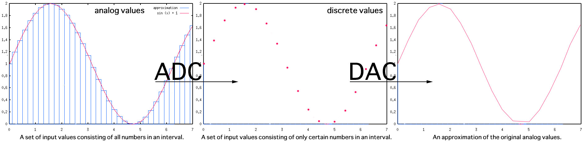
The resolution refers to the number of discrete values available over the range of analog values. The more, the better the accuracy. Here’s the same function rebuilt using a smaller resolution:
The purpose of this article is to discuss DAC and practical implementation options.
Circuit options
I’m going to discuss two methods for building the DAC module:
Method 1. A PWM generator with a low pass filter: we generate a variable duty cycle PWM signal. A low pass filter consisting of a resistor and a small capacitor is added:
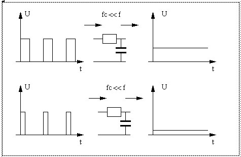
When the PWM signal goes high, it starts charging the capacitor, so the output voltage starts rising. When the PWM signal goes low again, it starts discharging the capacitor and the output voltage starts falling. The DC voltage at the output isn’t smooth, it keeps going up and down slightly around the average voltage, and effect called ripple.
For an Atmega8 microcontroller connected to Vcc=5V, this would allow us to generate discrete voltage values between 0 and 5V by changing the duty cycle for the PWM signal. A 50% duty cycle will produce 2.5V, while the 100% duty cycle will output 5V.
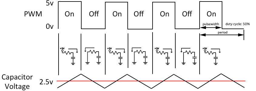
As for choosing the capacitor and resistor values, it’s a compromise: less ripple comes with a slower response to changes in the PWM value.
Method 2. A resistor ladder network, also called a R/2R ladder that consists of resistors and digital logic gates. The resistors act as voltage dividers between the referenced voltages:
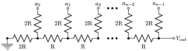
Bit a(n-1) (most significant bit) to Bit a(0) (least significant bit) are driven from digital logic gates (eg. microcontroller ports). Ideally, the bits are switched between 0 volts (logic 0) and Vref (logic 1). The R-2R network causes the digital bits to be weighted in their contribution to the output voltage Vout. Depending on which bits of a R-2R DAC of N bits are set, the output voltage Vout ranges from Vout = Vred x 1/2^N to Vout = Vref × (2^N-1) / 2^N
Obviously using a higher number of bits (higher DAC resolution) would allow us to generate a DC with a better granularity:
We can connect the R/2R logic entries directly to the microcontroller I/O pins and setting them LOW (0) or HIGH (Vref). But higher resolution applications are demanding in terms of numbers of pins used.
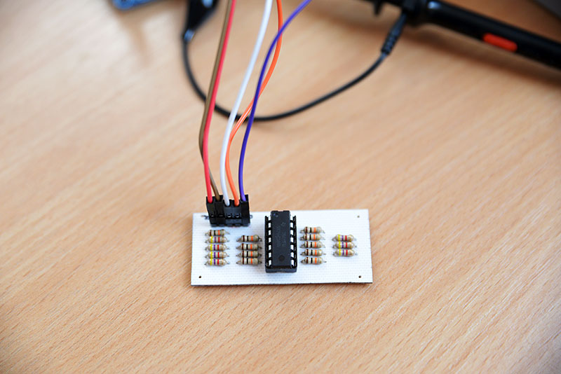
A serial Digital to Analog converter using R/2R network
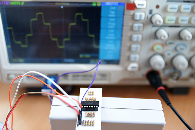
The idea is to go for a serial DAC, in order to save pins on the microcontroller. For this application, I’ve selected an 8bit shift register, the 74HC164, to use only two pins on the microcontroller and have the serial data converted to 8 parallel pins.
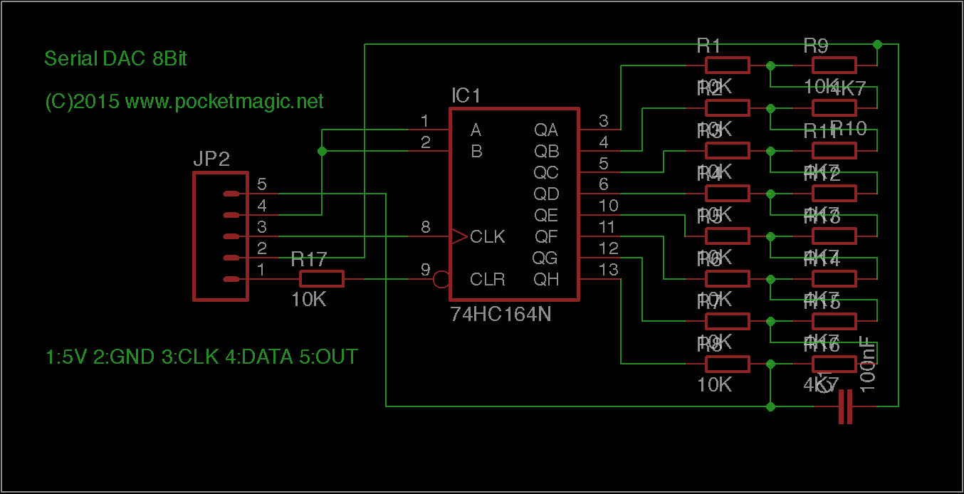
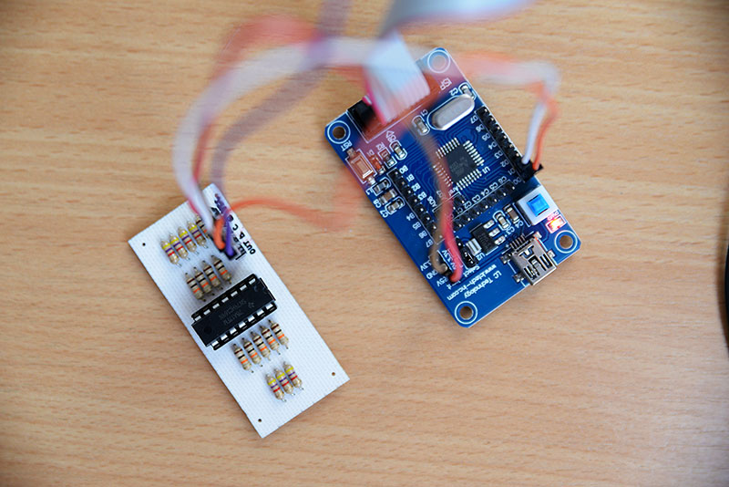
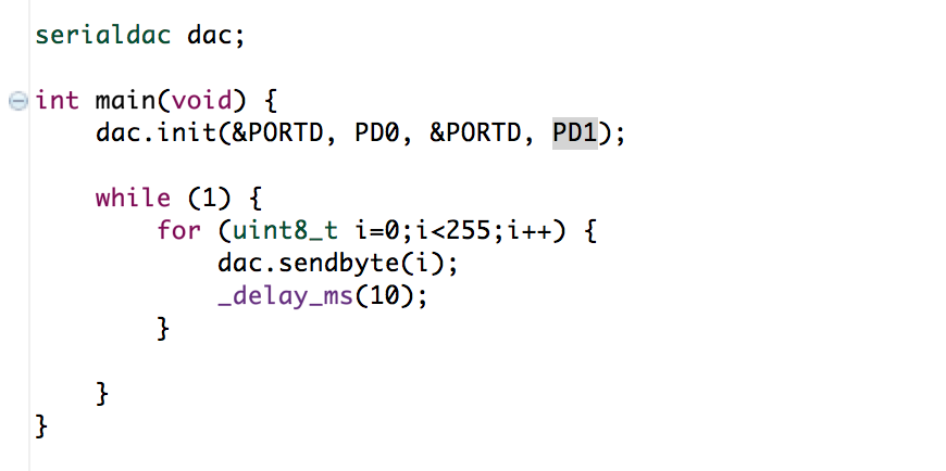
The 8 parallel output pins on the 74HC164 are further connected to an 8bit R/2R network. The functionality is straight forward: sending 8bit numbers over the two pin serial connection produces output voltages in the interval 0 and 5V. The code below is configured for an atmega8, with an external 16MHz crystal. The CLK is connected to PD1 and the DATA is connected to PD0.

The 100nF capacitor is needed to filter the R/2R output. Without it, or using a smaller value, a certain unwanted noise is being observed on the oscilloscope:
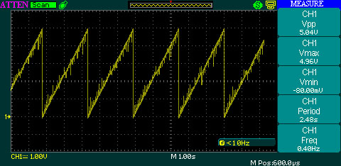
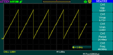
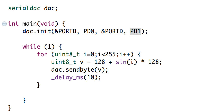
Finally, here is the sinus example. See the number generator used, equivalent to a f(x) = 1 + sin(x) function, and the result:
Download
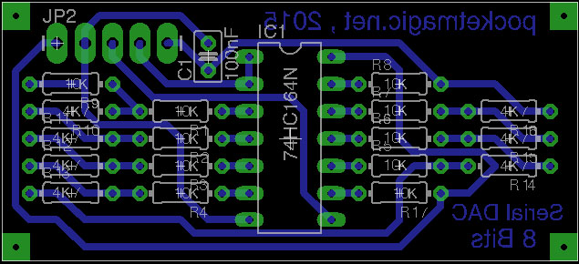
Attached please find the Eagle design files for this Serial Digital to analog converter, and the code used to test it on an Atmega8 microcontroller as serial data generator.
Atmega8 sample: serial_dac_code
Serial digital to analog converter eagle files: serial_dac_eagle
Please note that there are dedicated ICs doing all this, or even better (higher resolution). The purpose of this article is to present some of the details behind the DAC converters and the way they work.
Remarks
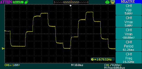
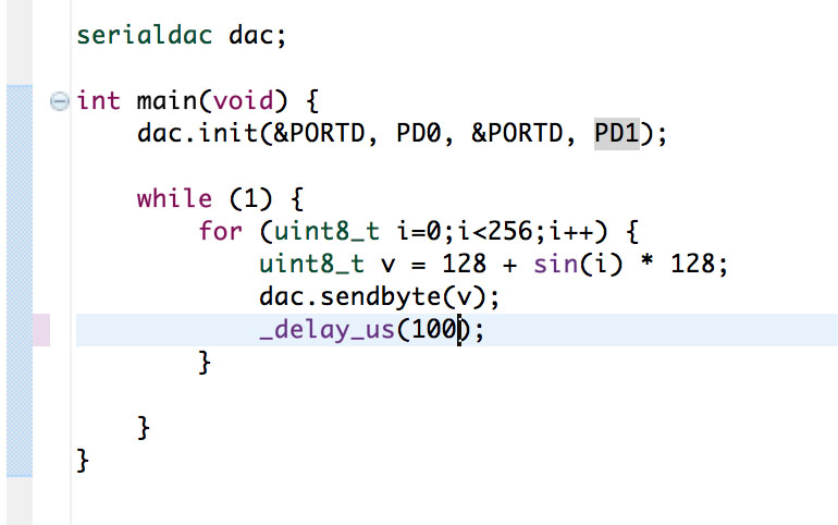
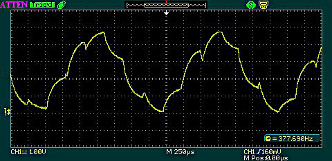
In the case of the shifted sinus function ( f(i) = (1+sin(i))*256 or f(i) = 128 + sin(i)*128 ), the resulting signal shape is influenced by the output capacitor and the time base of the generator. See the following code and it’s result, given the filter capacitor was set to 22nF . Notice that for higher frequency signals, choosing the right filter capacitor can become an issue.

Pingback: Digital bench power supply - PocketMagic