
I’ll have to go straight to the point: get yourself a CNC router now! I’m serious:
I used to make my PCBs dual layer and in the kitchen, as Hackaday folks like to show on their Twitter from time to time, but looking back, I can’t understand how I’ve done without a CNC router so far. And if you’re like me, and you probably are since you’re on this blog, such a tool is a must have.
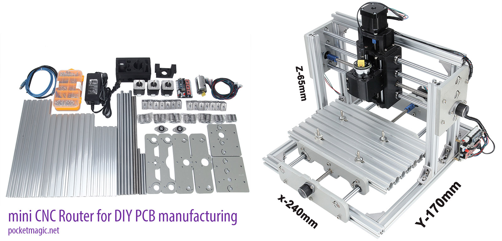
So I got myself a full metal frame CNC router KIT and a few drills and vbits for about $242 from a nice seller on Aliexpress (or amberzhuo313 on Skype). It got here fast, but because of some ongoing work, it stayed in its box for a few days.
One thing I was excited about was this CNC Router uses GRBL for command and control. This means I can use mostly any computer with an USB port to control it, or even build a simple control device with an SDCARD and a microcontroller, and have this going on its own, very much like my 3D printer.
Assembling the CNC Router
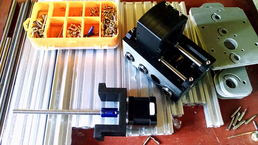
Be ready to spend about 6 hours of intense maker fun on building one of these units. The router came with detailed instructions, as a document with step-by-step images on what goes where.
The spindle holder was 3D printed, and all the rest was metal. The plastic parts where robust, with enough plastic to firmly join with the metal bars and screws:
The frame itself was designed with 2cm aluminium profiles, the versatile X shape variant that enables convenient mounting using the V-Slots. Another advantage of this design is that you can adjust it later to level the working surface, but you’ll need a perfectly planar surface for that.
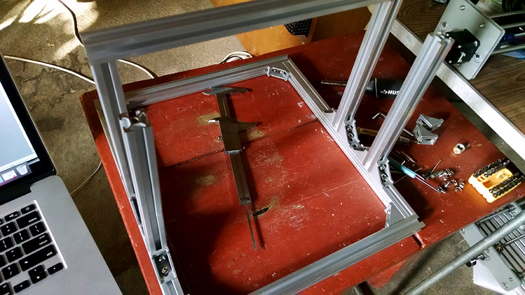
The construction was easy, after all what can you expect from a cartesian frame and a few wires:
The software
Windows
The tool came with software for Windows. Pars of this software is used to talk to the CNC’s Arduino Mini control board and send the GRBL format commands so the NEMA17 stepper motors would do the magic dance. The motors are controlled by A4988 drivers.
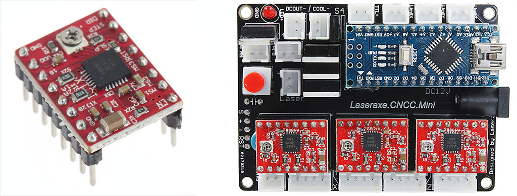
There’s a CH340 driver for the arduino control board and a “GRBLControl” program that opens a serial port to the CH340 and sends various GRBL commands, including batch files for engraving, milling, drilling and everything you normally do with a CNC router. Nothing fancy. The only issue is I needed the software for Mac OS.
Mac OS
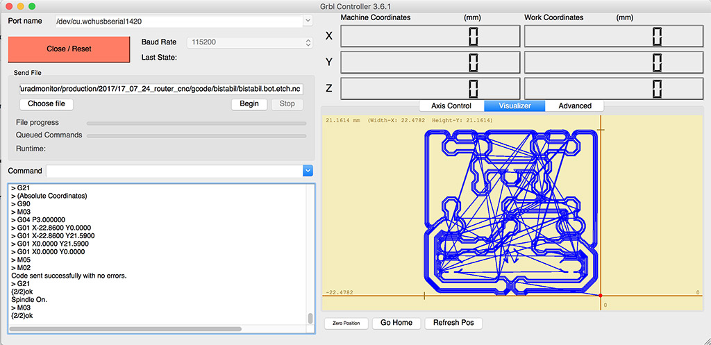
I have all my tools well integrated with Mac OS control software, with native applications. The driver for CH340 was already in place. For the controller I went for GRBLController, but as I said all this does is open a serial port and write GRBL commands as plain text. This one also has a visualization screen, to show the spindle’s path on the work surface:
PCB to NC
To generate the NC files with the GRBL batch commands, I went for the PCB-gcode ULP plugin for Eagle, available here. This amazing tool can export NC files directly from Eagle, including working sets for PCB etching (that is making the traces), drilling or milling. I would first etch, drill and finally mill out my PCB.
My first tests were with cardboard and wood, just until I learned how to use the new CNC Router. I used a default NC file I found in the software package, and fired it through the GRBL Controller. I didn’t even use the right bits, nor set any depth or speed options, but things were good and no drill was damaged:
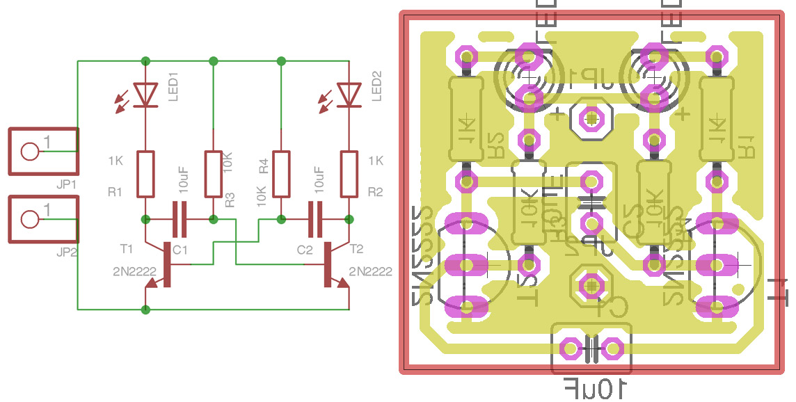
Next I tried one of my existing PCBs, but it was too large and each test took much time. So I designed a simple bistable circuit using two NPN transistors driving two LEDs (circuit is here):
The ULP plugin allows cutting the traces in multiples passes, and this is a great feature since it allows smooth CNC milling, I’ll post a picture with that a few lines later:
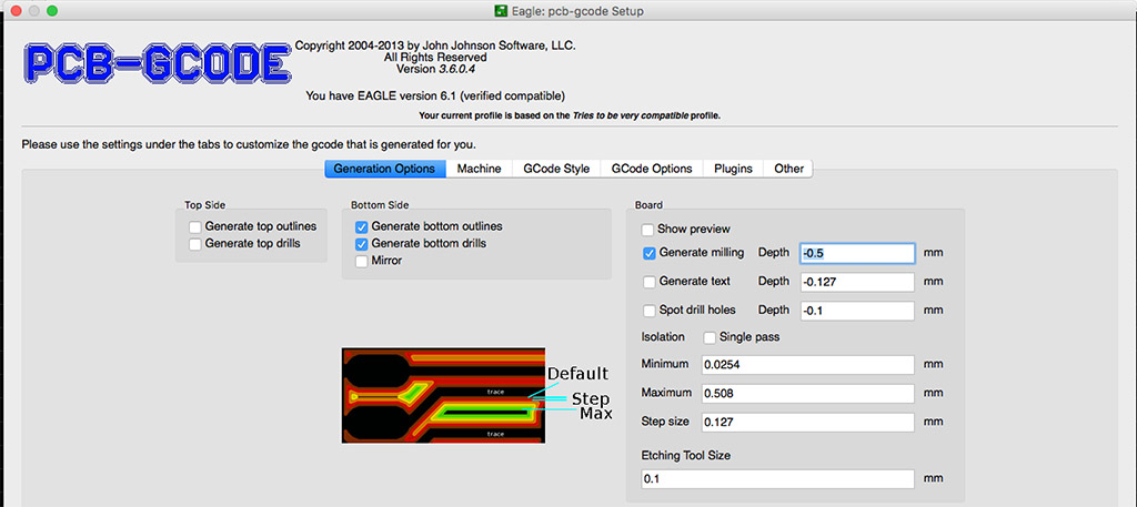
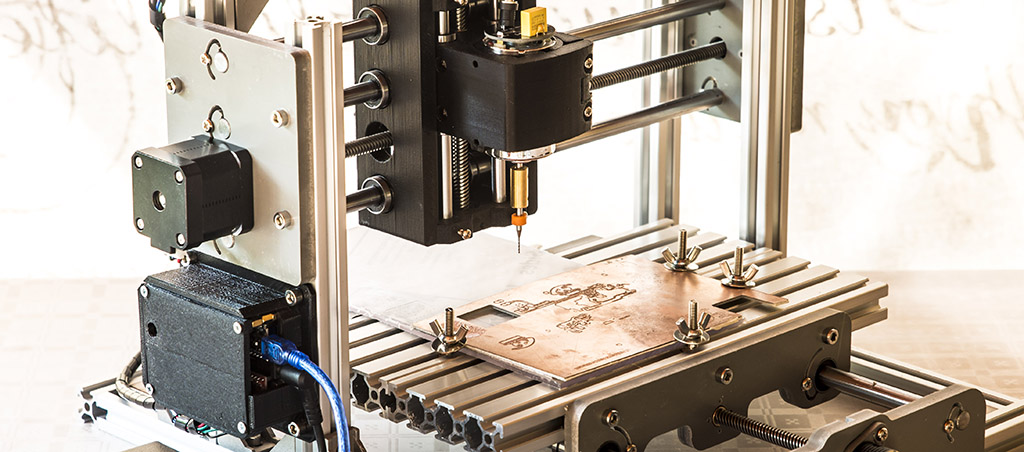
The first PCB looked promising, but the settings were bad, in this case the drilling depth was much too high. The cutting depth must be adjusted to match the copper layer plus a little extra tolerance:
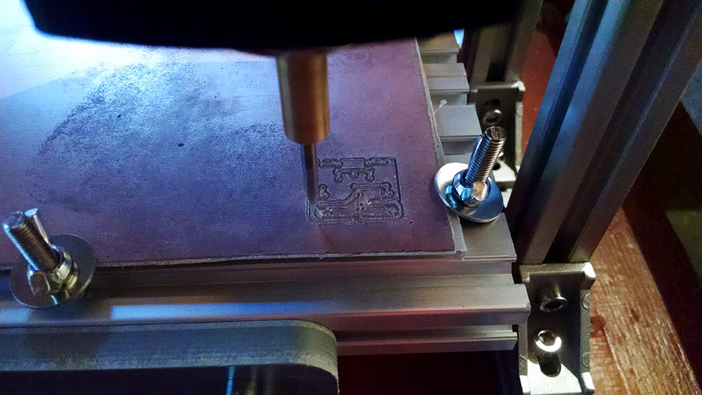
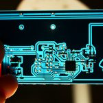
So I got that right and the results were surprising, see the etching:
And here is the drilling part:
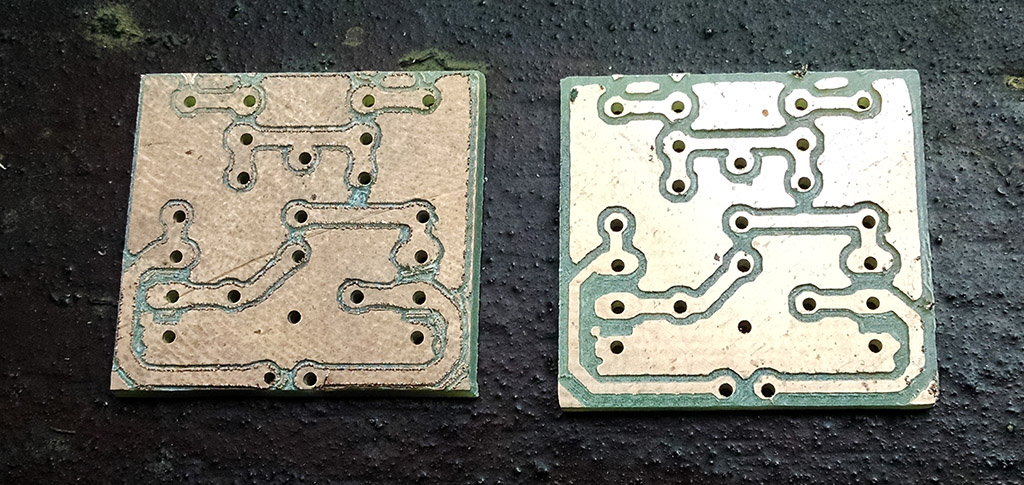
I was telling you about the multiple passes option in the ULP plugin, here is a picture showing two PCBs, left is single pass, while right is with multiple passes (if time is not an issue, got for the latter)
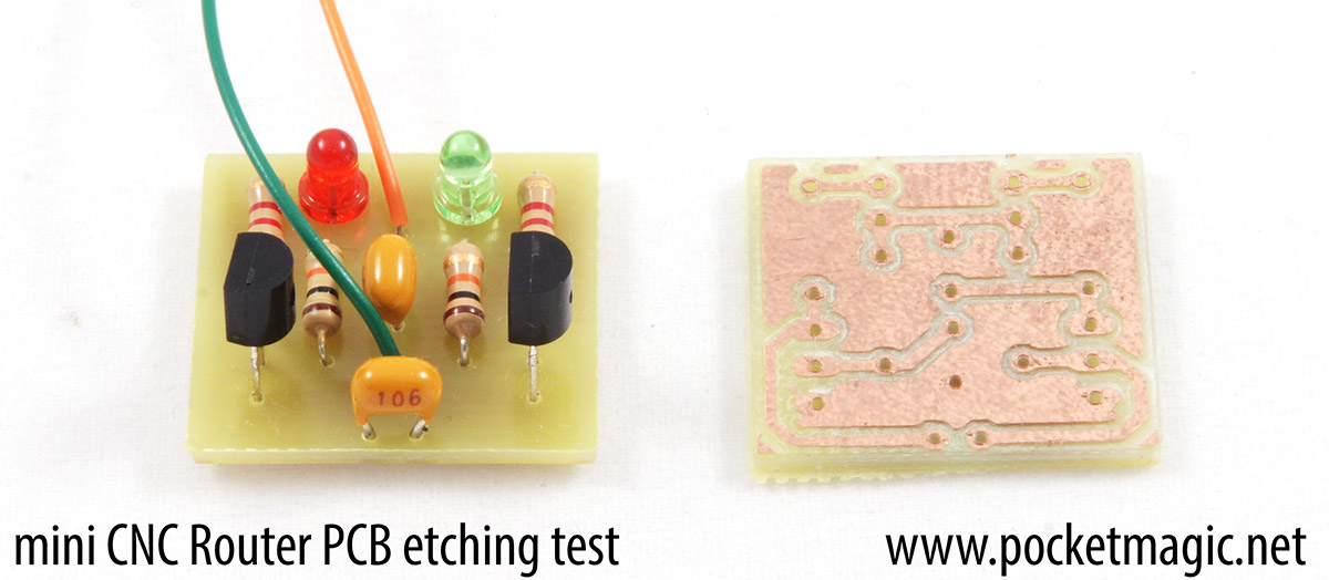
I was anxious to populate the first board and give it a test. Everything went well and I got my two LEDs blinking in no time. Here’s how it came out:
Is this enough for you to click that “buy now” button to get one of these routers yet?
Improvements
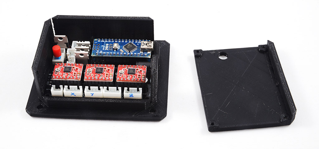
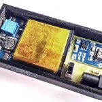
One thing I didn’t like was the GRBL Arduino board being exposed on the side of the machine. I decided to make a 3D printed enclosure for it, and have it installed in a proper location. So I took the caliper and translated all control board sized to the excellent 123D Design software:
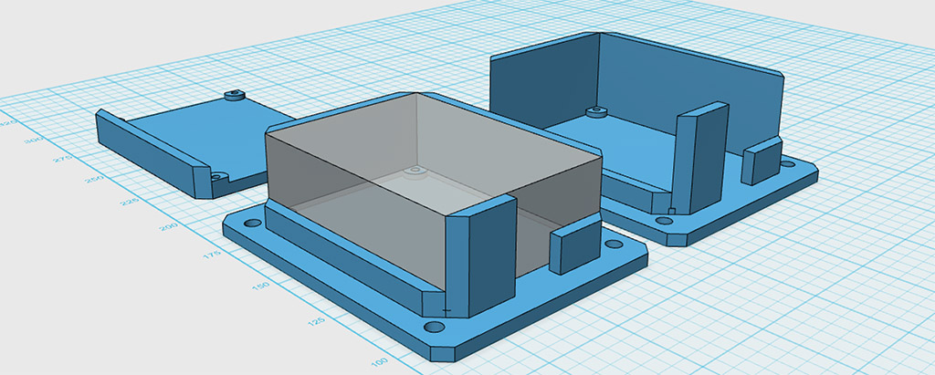
Minutes later, the 3D printer was already making it. Here’s the finished box with the controller board mounted inside:
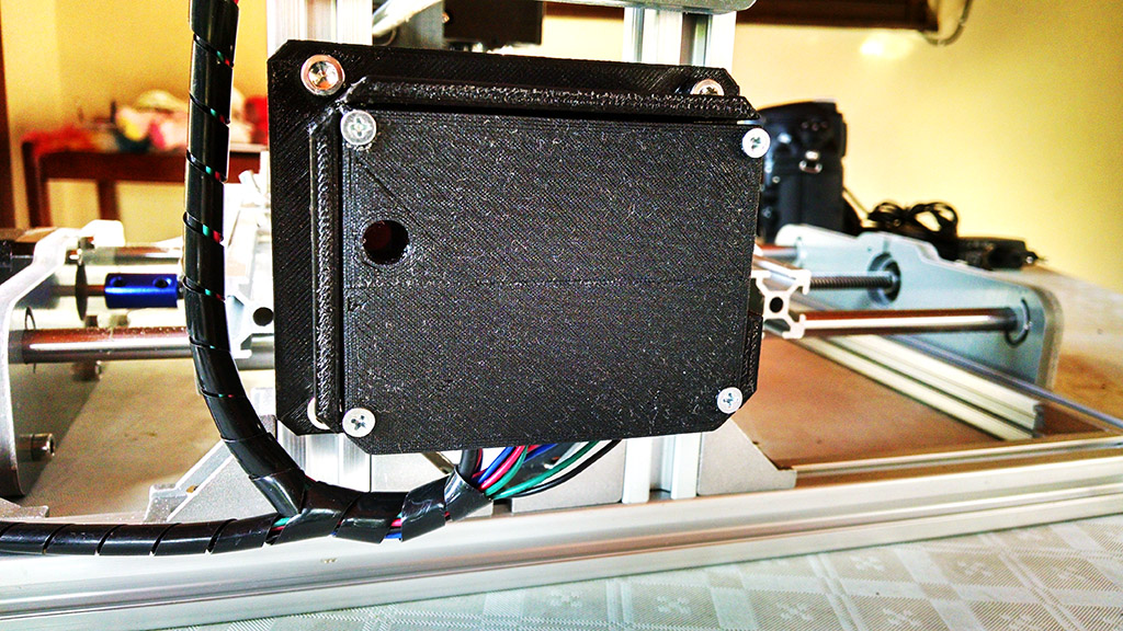
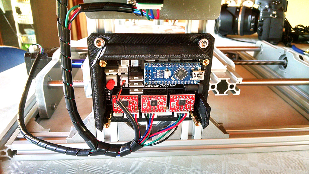
And here’s the controller mounted on the aluminium rails via the v-Slots, and the cables nicely organised.
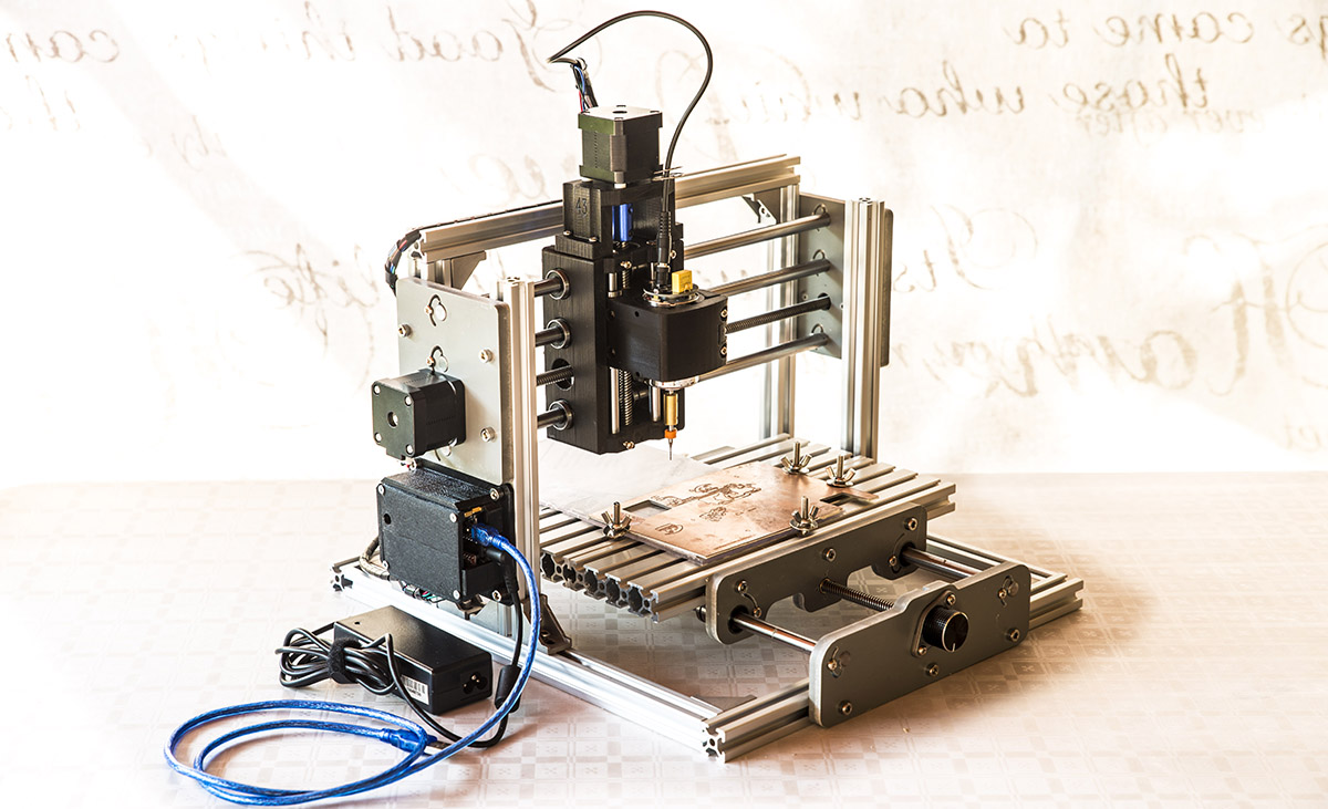
And the full unit for a absolutely gorgeous pose:
You can download the 3D files and print your own box, here.
Downloads
2417 Mini CNC Router assembly manual
Eagle PCB to NC ULP Plugin
GRBLController
Bistable LED blinker demo circuit files
GRBL Arduino Box 3D files
New firmware for 2417
My CNC came with GRBL v0.8. Due to an improper spindle connection, a high voltage spike erased my calibration settings and had to recalibrate my machine.
I installed the latest firmware attached here, using Arduino configured for Arduino Pro or Arduino Pro Mini.
Then via the serial terminal, I set all the configuration parameters again:
$0=10
$1=25
$2=0
$3=4
$4=0
$5=0
$6=0
$10=1
$11=0.010
$12=0.002
$13=0
$20=0
$21=0
$22=0
$23=0
$24=25.000
$25=500.000
$26=250
$27=1.000
$30=1000
$31=0
$32=0
$100=400.000
$101=400.000
$102=400.000
$110=500.000
$111=500.000
$112=500.000
$120=10.000
$121=10.000
$122=10.000
$130=200.000
$131=200.000
$132=200.000
You can test the movements on the 3 axes against a ruler, with something as simple as:
G91
G01 X50 F100
Should move the X axis to the right with 5cm.
https://github.com/1wise/grblv1.1h-laseraxe.cncc.mini
https://github.com/zlakomanoff/grbl-cnc-2417
Pingback: Automating PCB Construction – Part 0 | VA1DER