

|
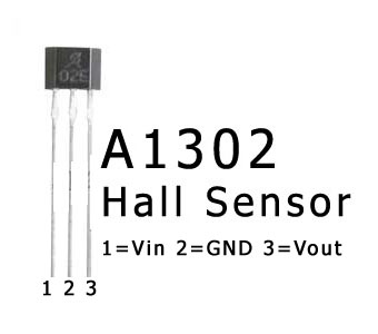
The A1301 and A1302 are continuous-time, ratiometric, linear Hall-effect sensor ICs. They are optimized to accurately provide a voltage output that is proportional to an applied magnetic field. These devices have a quiescent output voltage that is 50% of the supply voltage. This means that if you connect the A1302 to a 5V power supply and there is no magnetic field applied to this sensor, it will output a voltage of 2.5V. If you connect this voltage output to a microcontroller’s ADC port, having the maximum reference voltage of 5V = value 255 for 8bit ADC, the 2.5V will return a value of 128. |
Click the thumbnail below, to see an animated image with an A1302 test. I’ve used neodymium magnets for this test.

The sensor output goes from 128 to 255, by an exponential variation (the closer is the magnet, the bigger the value read).
Reversing the magnet, applies an opposed sign magnetic field , resulting in values lower then 128:

|

|

|
So you can also use the sensor to identify the North and South poles of a magnet.
The schematic for this circuit is very simple all you need to do is connect the VOUT pin of the A1302 to one of the ADC pins of your microcontroller:

You can check the datasheet for the A1302 here. The C Code for this project is available here.
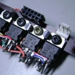
I’m planning to use this for a magnetic levitation device. The board was designed with a ATTiny45:

Cheers!
Radu Motisan

It is a very impressing application of A1302 . I am planning to build a AC current sensor by A1302. A panel cooling fan takes 500ma. AC. What will be the probale schematics so that A led will go on when I take the sensor near to current carrying conductor of the fan a LED will glow and will stop glowing when no current is flowing that is when fan is in OFF condition. can you please give me idea what will be the schematics without micro contrller
regards,
uttam Dutta
u.dutta@tatasteel.com
Hi Uttam.
I’m not sure the conductor would generate enough magnetic field to trigger the sensor, in my tests above I’ve used a strong neodymium magnet and I was getting readings from 2-3cm the most.
Anyway, what you need to do (assuming the sensor CAN pickup the magnetic field of the conductor) is simple:
– you don’t need a microcontroller
– simply connect the sensor to a 5V supply, and use the Vout PIN to open the Base of a NPN transistor through a 460Ohm resistor. Connect the transistor’s emitter to (-) , and between the colector and (+5V) put your led.
– the sensor will output a voltage of 0..2.5V on Vout proportional to the nearby magnetic field. So if it senses the magnetic field of the conductor, it will trigger the transistor.
– let me know if you need additional help with this.
Mr. Radu Motisan
Thank you very much for reply, I have tested as you told, when I brings the magnet pole near to A1302 led feds away.( in multimeter Voltage reduced to 0.71 volt from 2.42 volt ) and led become brighter when I brings the magnet near to opposite side of the A1302(also voltage level increased showing in multimeter.)
but there is no change of voltage level (i.e output of A1302) when I bring a AC or DC current (600 milli amp.)carrying conductor near to A1302.
Still I do not find any way to sense milli amp AC current by A1302 I I also don’t know whether it is possible or not.
Do you have any idea.
Regards,
Uttam Dutta
u.dutta@tatasteel.com
Hello Uttam.
Well as I already said, there were little chances the A1302 would sense the conductor’s magnetic field. But there is a good way of sensing it, without microcontrollers. Just one question before we start with that: what’s the voltage for the cooling fan?
Mr. Radu Motisan
Thank You for reply, Well it is 220 V AC and cooling fan takes approx. 500 milli amp. Then how it can be sensed whether fan is rotating or not. Please reply.
Uttam Dutta
u.dutta@tatasteel.com
The best way would be to tap into the conductor and detect the voltage there directly.
But if you want a non intrusive detector, have a look here:
http://www.pocketmagic.net/?p=1025
It is enough to bring the sensor a few milimeters near the conductor, and the led should turn on.
Mr. Radu Motisan,
Thank you for suggesting two ideas,in my case direct taping is not feasible, so I tried with the the circuit non
intrusive detector circuit.(http://www.pocketmagic.net/?p=1025)
I assembled the exact circuit in a vero, but LED remains conteniously ON when power is UP for this circuit,
Touching the metal prob connected with base of the first stage transistor makes the LED OFF momentarily and then it glows up again, and there is no effect found when I borught the prob to a AC current flowing conductor.
Can you further suggest something on this topic ,
Thanks and regards,
Uttam Dutta
u.dutta@tatasteel.com
Strange about the non-intrusive circuit. Are you sure you’re not touching any part of the circuit?
The led should turn on only when getting close to mains line. I’ll try to post some pictures with my setup. Please double check on your side too.
where do you buy sensor A1302?
because i need it.
thanks.
You can buy it here: http://stores.ebay.com/Thai-Shop-Etc
ok, thanks.
Hi Radu, i’m interested to make something of similar like your Magnetic Levitator…can you send me the project???
Please.
Thanks
Email: sasi@live@hotmail.it
That looks like a versatile base board. Where would I be able to get the design ?
Hi Radu,
I am trying to use this IC as a replacement of a potentiometer that is used in a speed controller for a DC motor. I feed 5V into it and I was expecting 0-5V out for my application. Instead, it puts out 2-4V. 2V when there is no magnetic field and 4V when the magnet is close to the IC.
Is there any way to convert 2V-4V into 0V-5V, or maybe should I use a different IC?
Thanks,
Florin
Salut Florin,
Vrei sa folosesti un senzor HAL pentru a controla viteza? Interesanta idee, sper sa poti sa pui niste poze daca iti iese. Am sa-ti raspund in engleza, poate intereseaza si pe altii.
If you look carefully at the details above, you will see the sensor returns 128 in idle mode (no significant magnetic field), 128..255 if the field produced by the north pole of a magnet, or 0..128 for the south pole.
For these values, being read using one ADC port, at a resolution of 8bits, it means you have aprox. 2.5V in idle mode, 2.5-5V for north pole field, and 0..2.5V for south pole field.
Please double check your readings in regards to these additional details!
Hi, Radu Motisan!
You don’t know how did you help me with your text above! Thanks so much!
But, I still have a doubt: about this A1302 (or A1301), there is a maximum magnetic field supported? I mean, if I put 1 tesla near the sensor, for example, the response will still be aprox. proportional?
thank you!!!
Lucas Cardoso, from Brazil.
Hi Lucas, glad this helps. I believe the sensor is limited to the max magnetic field it can measure. Please check the datasheet.