
Note: there is a newer version of this project, KIT1.1, see it here
If I was to give this project a version number, the closest match would be the uRADMonitor model B. Finally an open source compact radiation dosimeter, that has an LCD and thus allows mobile use, but also comes with an Ethernet adapter so it can do radiation monitoring (uRADMonitor compatible). Yet, this is not quite the uRADMonitor model B, just close. This is a DIY Geiger Counter Kit, that was designed due to popular demand. Now, all those asking for a uRADMonitor Kit have a nice alternative in this device. This circuit uses a single layer PCB and only trough hole components, making the construction so much easier for all the DIY enthusiasts. But this is not to replace the uRADMonitor model B, which will follow later this year.
Features
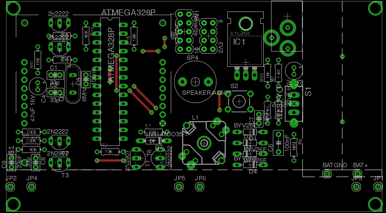
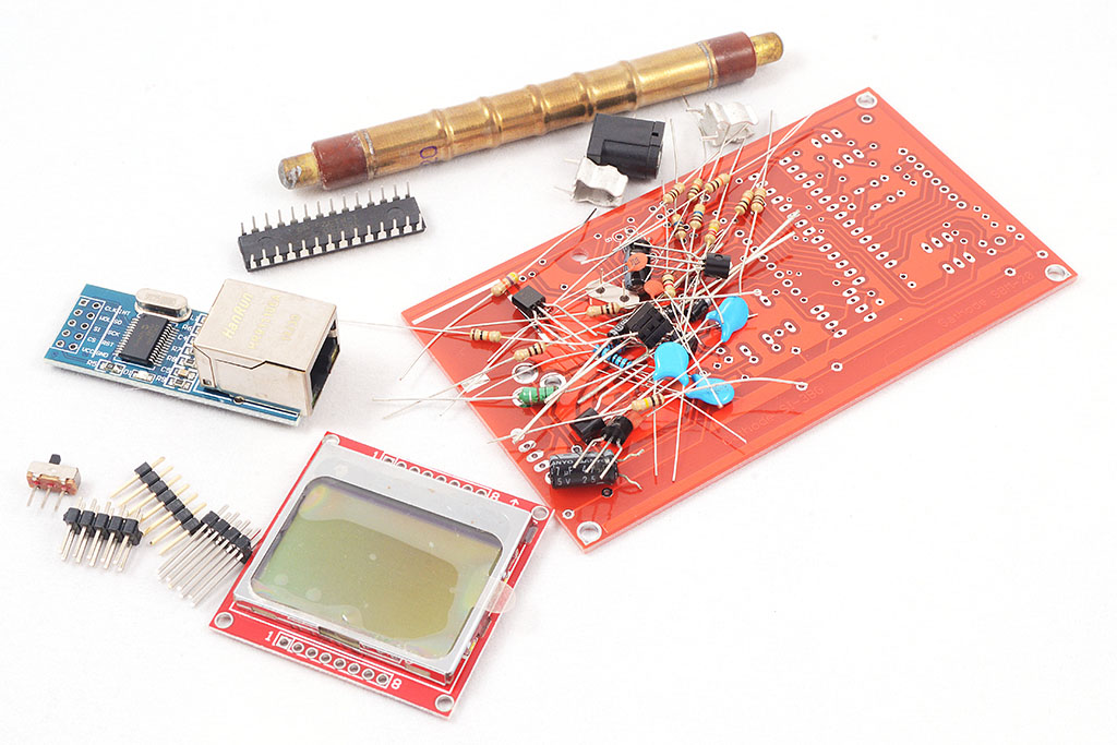
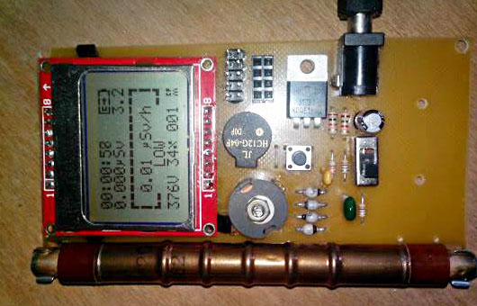
The video shows the first prototype, built using the toner transfer method. As said, it was designed using through hole components, on a single layer PCB board. It features the Atmel 328p microcontroller, as the central processing unit, that runs the firmware code. There’s a slot to mount a SBM-20 Geiger tube, a connector for the Ethernet module and one for the Nokia 5110 LCD screen. Both the LCD and the Ethernet adapter can be removed, allowing you to configure the final device: make that a portable dosimeter, a monitoring station or both. A speaker provides audible signals, including clicks and alarm, and a push button permits user interaction with the software. The bottom part of the PCB can be used to mount a battery holder for two alkaline batteries in series, or the unit can be powered using the DC connector, via a LM317 regulator. The entire board runs on 3V, and the high voltage inverter boosts that up to 380V (configurable in software up to 500V). The inverter uses a ferrite core transformer, connected to a switching transistor controlled via PWM signal by the microcontroller. An ADC port reads the high voltage level via a resistive divider, and adjusts the duty cycle so that the output voltage matches the value configured in the software. Therefore this is an efficient regulated high voltage supply.
More Details
The first time the unit is switched on, it will show the uRADMonitor logo. If the ethernet module is connected and the firmware is compiled with Ethernet support, the device will wait for a DHCP lease, part of the Ethernet initialisation procedure:

With the network cable properly connected, this takes around 11 seconds on most routers. As soon as the network settings are received, the unit shows the interface screen:
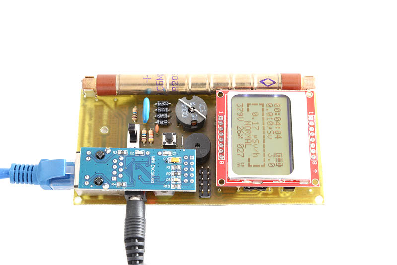
The firmware version at the time of writing this article contains three distinct user interface screens, that can be toggled using the PCB button. Besides changing the current screen page, the button also toggles the LCD backlight, which is turned off after a timeout of 10seconds, to save power. In case the dosimeter alarm is triggered by a high radiation dose, the user is automatically taken to the first screen, to see all radiation readings in real time.
The second screen page, shows some absolute readings, computed from the time the device was turned on, as no persistent storage has been used for this application:

The total time and the total number of pulses are used to compute the absolute average CPM. The maximum CPM is also displayed.
Finally, the third page shows the network settings, if the Ethernet module is connected and the Ethernet support enabled in the firmware: ip, gateway, netmask and the uradmonitor data server as resolved by DNS. Lot’s of network protocol stuffed inside this unit, and there is still plenty of memory left:
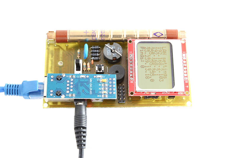
The ping counter was added for debugging purposes. It shows the number of pings received by the unit.
The circuit diagram
The schematics were designed using Eagle.
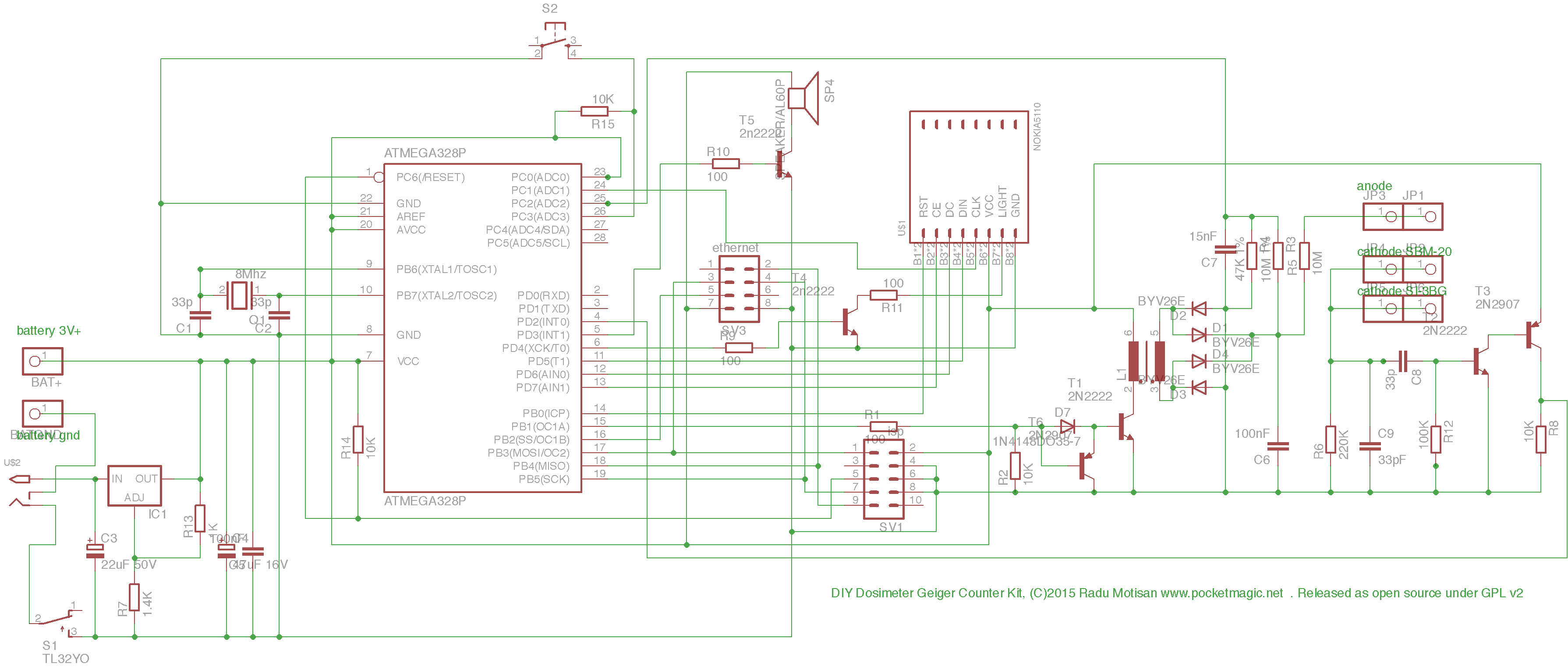

A few notes:
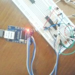
When mounting the Ethernet enc28j60 module to the PCB, the CLK and INT pins should be removed. We only need 2×4 pins for this application.
The T6 transistor is not required, and should not be mounted.
The Ferrite core transformer
It has a 16 turns primary with 0.2mm CuEm wire, and the secondary with 400 turns of thiner 0.07mm CuEm wire, all wound in the same direction. The Ferrite core itself is an ICE 22 core with a diameter of 1.4cm, and an AL of 2800. For any additional questions, use the comments section of this page.
Released as Open Source
This entire work has been released under GPL v2. It includes the circuit diagram as Eagle files, and the firmware source code. Revisions will be added from time to time, to fix bugs or bring enhancements. To review the GPL v2 license, click here.
Source code repos are available on Github or a first code release can be downloaded here.
Precompiled firmware / hex file
For those of you that want to avoid the hassle of downloading and compiling the code, I have included the compiled code below. One variant is a simple, offline code that works without the Ethernet module, while the second adds support for Ethernet as well.
offline-firmware
enc28j60-module-firmware
Some instructions on how to burn a hex firmware file to the microcontroller are provided in this article.
Final notes
Code for joining the uRADMonitor network is currently available only on request due to sensitive security details involved.
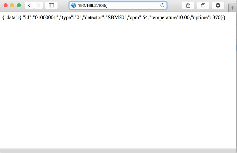
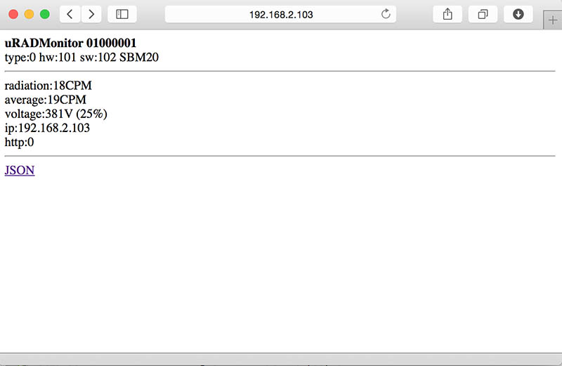
With the Ethernet enabled firmware and an enc28j60 mini module correctly connected, you’ll be able to access the unit via the LAN, in a similar fashion to the official uRADMonitor units:
Upgrades
There is a newer version of this project, KIT1.1, see it here
Variants built by others
Mykola did an excellent job at completing his KIT1 dosimeter from scratch, including the PCB and the ferrite core. The display shows it is already operating successfully, and once Mykola gets a network module to plug it in the 2×4 connector, he’ll be able to join the uRADMonitor network with the first node in Ukraine.
Frank posted a video of his new uRADMonitor KIT1 equipped with an enc28j60 network adapter. Looks great Frank! can’t wait to see your data online
Antonio went the PRO way:

Doru built everything from scratch, and he still needs to add the ferrite transformer and the Geiger tube:

Hi Radu, where you can buy the Ferrite core ICE 22 core with a diameter of 1.9cm, and an AL of 2800? You have to tell me a link? It seems to be the only component hard to find.
Antonio.
Hi Antonio,
Here are a few ferrite cores with high AL that you can use – just check their sizes, some might be too wide:
http://www.ebay.com/itm/251473390888
http://www.ebay.com/itm/251681418244
http://www.ebay.com/itm/261809505724
http://www.ebay.com/itm/371232188228
http://www.ebay.com/itm/251786155768
http://www.ebay.com/itm/261585024927
http://www.ebay.com/itm/251637609074
http://www.ebay.com/itm/251637564839
http://www.ebay.com/itm/261585030974
I will publish a new revision that uses an off the shelf ferrite choke instead of the more complicate current ferrite core transformer – that needs to be constructed manually, to make it easier for the DIY maker.
Hi Radu,
Just a precision for peoples sourcing CuEm cables:
0.2mm CuEm wire is know on ebay as: “32AWG magnet wire“. Ie: http://www.ebay.com/sch/i.html?_nkw=32AWG+magnet+wire
0.07mm CuEm wire is know on ebay as: “41AWG magnet wire“http://www.ebay.com/sch/i.html?_nkw=41AWG+magnet+wire
Hope it helps!
Radu,
I’ve found a Guy who use a standard audio transformer (LT700) to drive HV.
Maybe this could simplify processus of building a urad device?
Have a look at Dave Mouat version, here:
http://www.techlib.com/science/geiger.html
Hi Martin,
Thanks for sharing the wire details, those will surely be helpful to those interested!
The uradmonitor model A use a smart low size inverter that I’ve developed some time ago:
http://www.uradmonitor.com/wordpress/wp-content/uploads/2015/02/compensation_capacitor.jpg
(just above the Ethernet connector). After I launch the project on indieGogo my plan is to release it as open source.
But until then, this KIT variant is available. Iron core transformers (LT700) can work but they are bigger that the sizes required for a ferrite core variant, thus my choice.
Building such a transformer is not that hard, here are more examples of such a construction:
http://www.pocketmagic.net/3v-to-400v-regulated-inverter-for-geiger-counters/ (this has 3 windings: primary, feedback, secondary)
http://www.pocketmagic.net/diyhomemade-portable-radiation-dosimeter/
http://www.pocketmagic.net/uradmonitor-online-remote-radiation-monitoring-station/
http://www.pocketmagic.net/diyhomemade-geiger-counter-2/ (again, this uses 3 windings one extra for the feedback)
http://www.pocketmagic.net/global-radiation-monitoring-network/#130710
http://www.pocketmagic.net/global-radiation-monitoring-network/#130728
I’d be happy if you would try building your own variant, and can help you with any questions. There will be an update to this kit circuit, but not soon.
Buna Radu,
M-am gandit sa folosesc si eu un Dozimetru in regim online.
De unde cumpar unul si la ce pret?
In kit (neasamblat) nu se poate?
Sau macar niste componente mai ieftine.
De construit dureaza!
Bafta.
Ok Radu, then want to use the ferrite core, no problem, so I wanted to ask you, do you think this is good? http://www.ebay.com/itm/251637564839.
Another information, wanting to use the LND712 that requires 500 volts how to get them with the survultore kit1?
Antonio.
Hi Antonio, the core is good, but the size is too big and will not fit on the PCB.
The core I’ve designed the PCB for, is a 1.4cm diameter one.
You can use one of these: http://www.ebay.com/itm/251637609074
Good news, then proceed to purchase. I apologize, and to the problem of 500 volts can it?
Antonio.
Yes, 500V can be selected in the software.
Hi Radu,
At the moment I am in Romania . It is a place where they can buy “DIY Geiger Counter Dosimeter Kit” assembled or not?
Help me !
@Lora salut Doru. Cum ti-am raspuns si pe email, acest kit e oferit celor interesati sa-l construiasca. Nu dispun decat de o singura bucata pe care am construit-o manual pentru scopul acestui articol. Instructiuni complete de constructie au fost oferite mai sus. Pentru orice intrebari tehnice, iti stau la dispozitie.
Hello Radu, I did make the circuit and I’m collecting all the components, these days weld the everything. I have to ask you something, ok for battery power at 3 volts, but that range volt input to LM317T? 5, 9 or 12 volts?
Thank you, Antonio.
Hi Antonio, for the battery 3V is ok, as this is used directly. For the DC Jack, you can use 5V to 9V and that goes through the LM317. 12V is a bit too much. When the DC plug is connected, the battery is disconnected automatically.
I am looking forward to see pics with your circuit! I will send you a hex file when ready.
Buna Radu,
Stiu, este duminica si nu doresc sa te bat la cap cu problemele mele.
Totusi, am construit Detectorul de radiatii – modelul acesta “B” prezentat si sub
denumirea de “DIY Dosimeter Geiger Counter Kit” .
Toate bune si frumoase, cu fisierul “offline-firmware” functioneaza minunat insa cu fisierul “enc28j60-module-firmware” se intepeneste in “ecranul – 1”
prezentat in poza de mai sus!! Ce se-ntampla? Am facut EU vreo greseala sau este valabila fraza din text “Codul pentru aderarea la rețeaua uRADMonitor este disponibil numai la cerere , datorită detaliilor de securitate sensibile implicate.” As dori totusi sa-l conectez la monitorizarea online. Cum fac?
Pot avea acces la vreun “firmware” mai nou sau upgrade-urile la care se face
vorbire sunt doar pentru constructiile mai noi, in varianta SMT?
Multumesc,
D.Sandu
salut Doru,
Felicitari pentru constructie. Te rog trimite-mi cateva poze, sunt chiar curios sa vad cum ti-a iesit. Gasesti adresa mea de mail sub sectiunea “About” pe acest blog.
Intre timp am sa pregatesc firmware-ul cu care poti transmite date online si am sa ti-l dau ca reply la mail.
Radu
Pingback: dosimeter | Fusor.info
Pingback: DIY Geiger Counter Kit 1.1 - PocketMagic
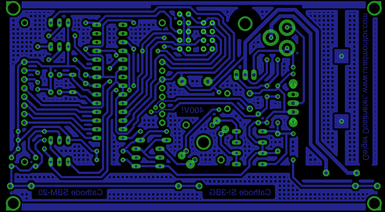
Salut Radu, poti sa postezi pcb-ul v1.1 fata si spate intr-un fisier pdf? Ar fi mult mai simplu de facut cu metoda de transfer termic. Mersi.
@Bebe, am postat, in articolul despre KIT1.1, link direct aici: http://www.pocketmagic.net/wp-content/uploads/2015/10/KIT1.1.102_PDF.zip
Pingback: The uradmonitor KIT1 is the first open source radiation dosimeter that was designed as a DIY radiation tool. It can be used to push data to the uRADMonitor network.
Pingback: Model KIT1 - Production Ready! - uRADMonitor