
For most of my microcontroller related projects, I try to describe everything in detail, but I just realized I didn’t pay enough attention to showing how to set the AVR fusebits to make the AVRs work with various external crystals, 8MHz, 16MHz, etc. I mostly work with mega microcontrollers (atmega8, atmega16, atmega128, atmega168, atmega328p) but the information in this article applies to all the other AVR microcontrollers.
Hardware tools
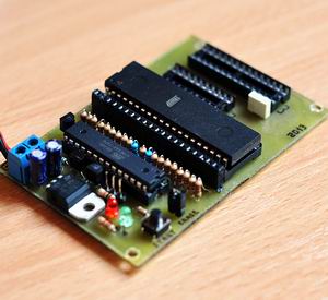
To set the fusebits you can use the same tool you use to write the .hex. In my case, this is my trusty USBAsp USB programmer, that works great!
Software tools
Here things get a bit more complicated. On one hand you need the software that works with USBAsp, but on the other hand you need to correctly compute the fusebit values that will be programmed in your AVR.
For the first I use Winavr. If working with a command prompt line tool seems complicated to you, consider using alternatives such as Extreme burner.
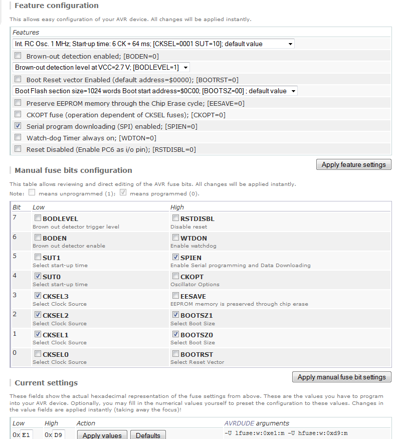
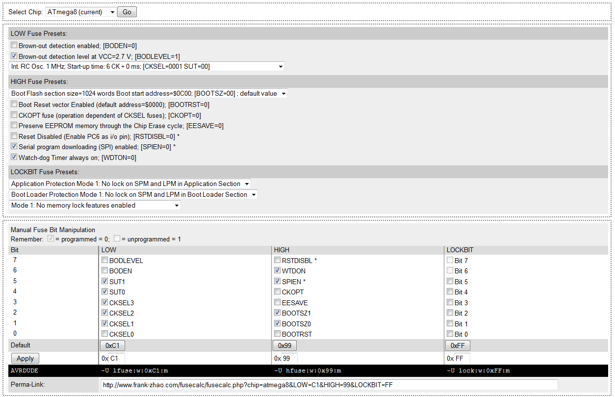
For computing the fusebits, there are quite a few online webpages that help you achieve the goal in easy steps: here or here . Any of these two will do. Accessing one of these pages, you must select the AVR you need to program the fusebits for , then several tables with apparently complicated settings show up:
To help you get going, here are a few details you should know:
Clock selection
This controls how the chip is clocked. The drop down menu shows a big list of options, but reading those carefully you’ll quickly see they all mention the Clock Source and the Clock Startup. Wrong clock settings can make your AVR unusable. If this happens, see the Fusebit doctor below, to learn how to reset the fuses and “revive” your AVR.
The Clock Source contains the following:
External Clock, Internal 8MHz clock, Internal 4MHz clock, Internal 128KHz clock, External Crystal (0.4-0.9 MHz), External Crystal (0.9MHz – 3.0MHz), External Crystal (3.0MHz – 8.0MHz) or External Crystal (8.0MHz +)
The Clock Startup can be one of the following:
14CK + 0 ms, 14CK + 4 ms, 14CK + 65 ms.
External Clock means that a square wave is being input into the CLOCK-IN pin by using a clock generating chip. This is uncommon and usually you won’t be needing it.
Internal Clock sets the avr to use the internal oscillator that is not very precise but good for most projects that don’t have fine timing requirements. You should know that this clock varies with temperature and the power supply voltage. You can chose from a 8MHz, 4MHz or 128KHz clock. The 128KHz clock is for very low power applications where the low speed helps conserve power. By using the internal clock, you don’t need to wire up a crystal so we can use the XTAL1 and XTAL2 pins for various other purposes.
External Crystal option is used when you need a special clock rate, like 8MHz or 12MHz or a high precision clock that will not vary with temperature or power supply voltage fluctuations. In this case you need to connect an external crystal or oscillator.
The Startup Time is a short delay, used to pause the clock for the given time, the very first time the power is applied. To be on the safe side, go with the longest setting 14CK + 65ms unless you know for a fact your settings must be different.
Clock Output (available for some AVRs only) produces a square wave of the same frequency of the clock input (internal, external, crystal, etc) on a given pin (D2, B0, etc). This is useful if you’re debugging the clock rate, or if you want to use the clock to drive another chip.
Clock Divide (available for some AVRs only), causes the chip to divide the clock rate by 8. So if the clock source is set to Internal 8MHz and you have this fuse set, then you’ll really be running at 1MHz. By default, this is turned on.
Reset Disable, turns the Reset pin into a normal pin instead of a special pin (as it is set by default). If this fuse is enabled (Reset Disabled), you won’t be able to program the chip using ISP anymore. Be careful about this option, and never set it on, unless you really need the one extra pin. If you set this fuse in error and you can’t access your AVR anymore, see the Fusebit doctor, to learn how to reset the fuses and “revive” your avr.
Brown-out Detect fuses set the voltage threshold for the Brownout protection circuitry on. A “brown-out” happens when the voltage drops and your clock radio may stop working: the power voltage is too low to run reliably at the predefined. ex: ATtiny2313 can run as fast at 20MHz but only if the supply voltage is between 4.5V and 5.5V. If the voltage decreases below 4.5V, the AVR may behave erratically, erasing or overwriting the RAM and EEPROM, it may also start running random piece of the flash program, all in one an action with unpredictable results, nothing you would want your hardware to do. To keep it under control, set the brownout voltage to 4.3V. If the voltage goes below this threshold, the chip will turn off until the voltage returns. It will then reset and start over. If the chip is meant to run at 5V, set the brown-out to 4.3V. If the chip can run as low as 3.3V you can set the brown-out to 1.8V. If the chip is a ‘low voltage compatible’ chip such as the attiny2313V (which can run as low as 1.8V if its clocked at 4MHz or less) then you can set the brownout to 1.8V. You can read more in the datasheet.
By default, this option is disabled. If your AVR uses a bootloader or the EEPROM, you must set the BOD for safety!
SPI programming (SPIEN fuse), if this fuse is not enabled, the part must be programmed using high-voltage, and the SPI interface will not be usable (so no USBASP for you). Be careful about disabling this fuse, as without a high voltage programmer, your AVR might become unusable. Also see the Fusebit doctor below, to learn how to reset the fuses and “revive” your avr.
As a result of carefully choosing the FUSEBIT Settings, you get several numbers in HEX, representing the LOW FUSE, the HIGH FUSE, and for some AVRs the EXTENDED FUSE.
To set them with AVRDUDE (WinAVR) or Extreme Burner, see the examples below:
Examples
ATMega8 default settings: 1MHz internal oscillator
avrdude Syntax:
avrdude -p atmega8 -c usbasp -U lfuse:w:0xE1:m -U hfuse:w:0xD9:m
Extreme burner
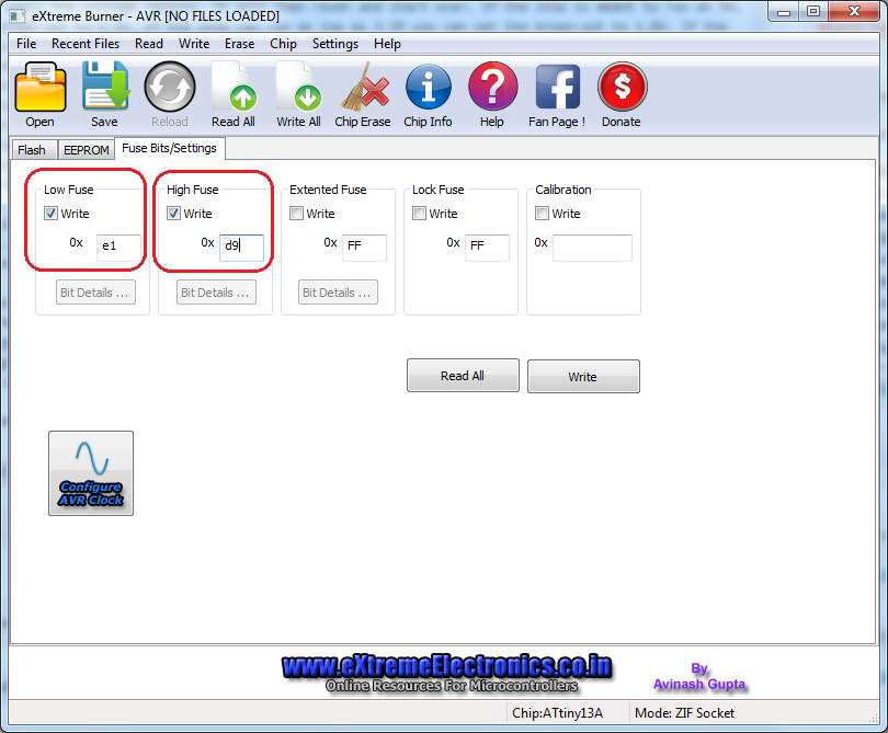
As you can see the lfuse and hfuse numbers are the same (0xE1 and 0xD9). To save on article length, and increase readability, I will only show the AVRdude settings, while you can easily insert those numbers in Extreme Burner for the same results.
ATMega8 8MHz external crystal
avrdude -p atmega8 -c usbasp -U lfuse:w:0xDC:m -U hfuse:w:0xD9:m
ATMega8 16MHz external crystal
avrdude -p atmega8 -c usbasp -U lfuse:w:0xFF:m -U hfuse:w:0xC9:m
ATMega128 default
avrdude -p atmega128 -c usbasp -U lfuse:w:0xE1:m -U hfuse:w:0x99:m
ATMega128 16MHz external crystal fuses
avrdude -p atmega128 -c usbasp -U lfuse:w:0xFF:m -U hfuse:w:0x89:m
ATMega168 default fuses, 1MHz internal oscillator
avrdude -p atmega168 -c usbasp -U lfuse:w:0x62:m -U hfuse:w:0xDF:m -U efuse:w:0x1:m -U lock:w:0xFF:m
ATMega168 16MHz external crystal fuses
avrdude -p atmega168 -c usbasp -U lfuse:w:0xdf:m -U hfuse:w:0xDF:m -U efuse:w:0xF9:m -U lock:w:0xFF:m
ATMega328p default fuses, 1MHz internal oscillator
avrdude -p atmega328p -c usbasp -U lfuse:w:0x62:m -U hfuse:w:0xD9:m -U efuse:w:0x7:m -U lock:w:0xFF:m
ATMega328p 3-8MHz external crystal
avrdude -p atmega328p -c usbasp -U lfuse:w:0xdc:m -U hfuse:w:0xDF:m -U efuse:w:0xFF:m -U lock:w:0xFF:m
ATMega328p 16MHz external crystal fusebits settings
avrdude -p atmega328p -c usbasp -U lfuse:w:0xdf:m -U hfuse:w:0xDF:m -U efuse:w:0xF9:m -U lock:w:0xFF:m
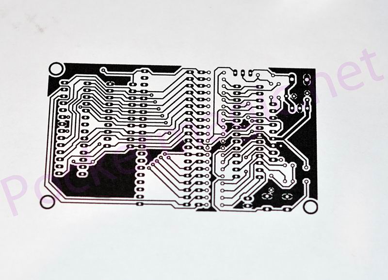
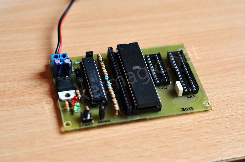
Fusebit doctor
The fusebit doctor, designed by manekinen, is a device for repairing dead ATmega and ATtiny family AVRs by writing the default, correct fusebits. Most common causes for dead AVRs, are wrong clock source settings (CKSEL fusebits), disabled SPI programming (SPIEN fuse) or disabled reset pin (RSTDISBL fuse). This circuit uses the parallel and serial high-voltage programming method: HVPP = high voltage parallel programming and HVSP = high voltage serial programming.
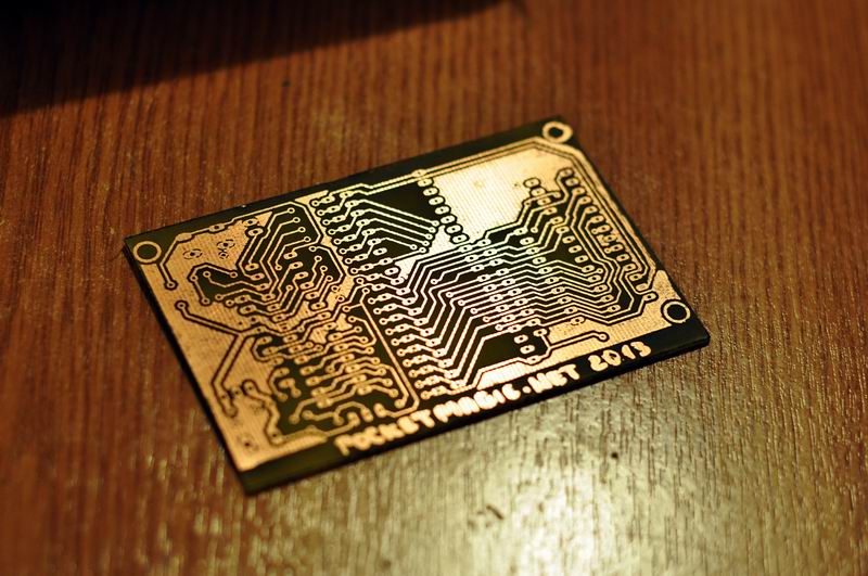
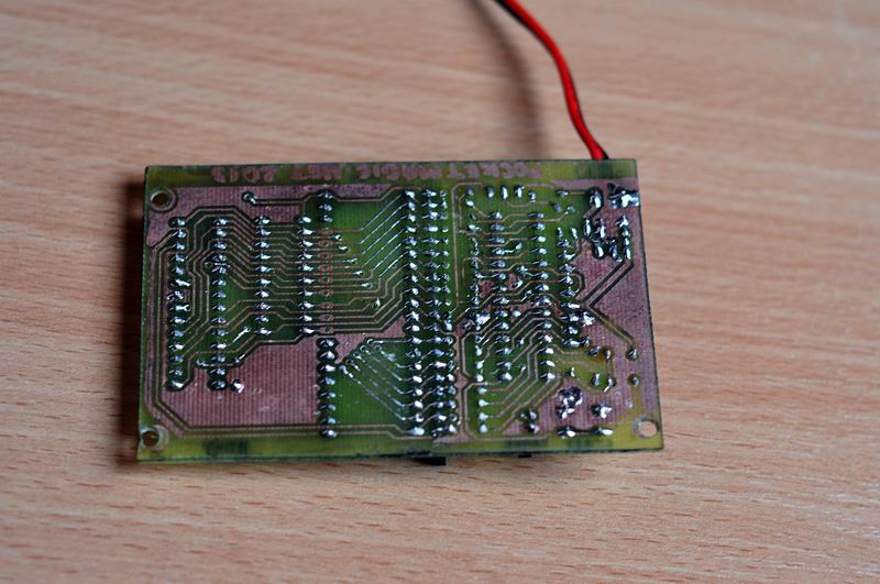
Manekinen’s device come with a database of supported chip, stored in the board’s main microcontroller, that is used to recognize the faulty chips, and restore their original settings. To do this, we only need to place them in the correct socket and press the START button. So easy. As all project resources have been kindly provided by the author, I built my own board to repair some of my faulty chips.


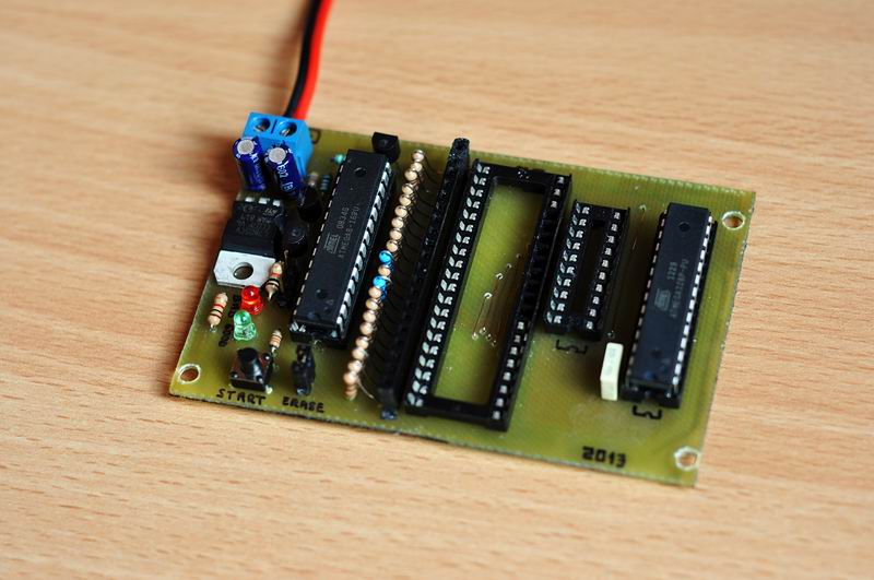
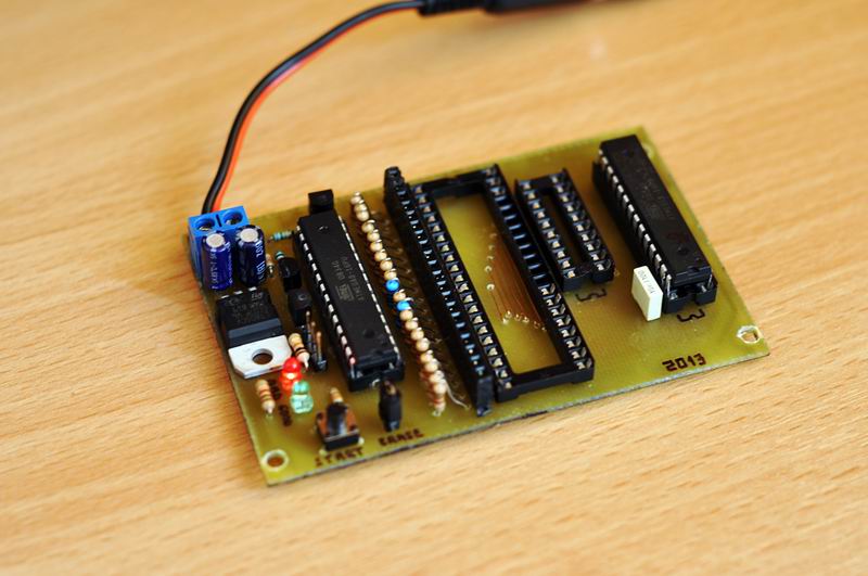

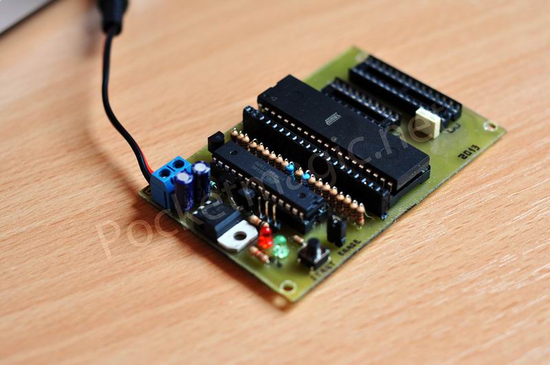
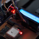
One of my atmega328p’s had faulty fusebit settings, because of some complications while writing its firmware. To revive it , I put it in the AVR Doctor’s socket, and pressed the START button. Almost instantly the GREEN Led turned on, and the “patient” was cured. So simple.
Pingback: Coil Winding machine counter with Atmega8 and Reed relay « PocketMagic
Pingback: DIY Dosimeter Geiger Counter Kit - PocketMagic
Pingback: DIY Geiger Counter Kit 1.1 - PocketMagic