
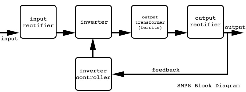
A switched power supply is an electronic power supply that converts electric power efficiently. They work by feeding a DC voltage (rectified from AC first, where needed), to a ferrite high frequency transformer via a controlled oscillator. The output rectifier converts the high frequency AC output to DC. A feedback mechanism (usually done via an optocoupler regulates the output). By taking this approach, the variable duty cycle of the oscillation and the transformer parameters, can be used to control the output voltage and current.
Building a simple switched power supply is easy! The schematics below were designed by Daniel. All credit goes to him. I did not test these supplies, but looking over the circuits they seem to be correct. There is little that can go wrong with the simple designs, for the more complicated ones you should double check. You can find more of his projects on his webpage. Don’t get scared by his messy test boards, he actually has some very interesting ideas!
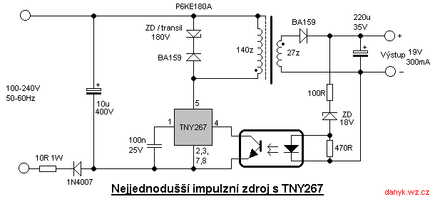
1. Simplest SMPS . Details here:

It is a low power supply, using an optocoupler to regulate the output. Easy and straight forward.
2. Single bipolar transistor SMPS. Details here.

It uses a high voltage transistor in a simple Armstrong oscillator with feedback coil. The output is regulated using an optocoupler.
And here is a second variant, using better rectification:

Finally, another variant, that uses even fewer parts, an no optocoupler:

3. Mosfet driven 90W SMPS . Details here.

This also includes a basic short circuit protection.
4. UC3842 SMPS. Details here.

A great yet simple example of using the dedicate UC3842 SMPS IC. It doesn’t use an optocoupler, so regulation is not perfect. Instead it uses a feedback coil.
Here is a better variant, using an optocoupler:

5. IR2153 SMPS. Details here.

This is a higher power supply, as it uses a half bridge to drive the ferrite transformer. Unfortunately it is not regulated by IR2153 limitations (no feedback), but still a great circuit.
Another variant is available here.

Here is a very high current supply:

Great for some exotic applications, this circuit uses several mosfets in parallel driver by the IR2153 via totem poles. The command part of the circuit needs enough current to be able to open the gates of all mosfets. I do not recommend this approach.
6. UC3844 SMPS with optocoupler. Details here.

A better SMPS, as it uses both a dedicated IC, and a correct feedback mechanism with an optocoupler.
7. High power SMPS for welding. Details here.

Daniel incorrectly named this “inverter”. It is still a high to low voltage supply, with poor voltage regulation, but capable of a huge current.
Here is another variant that comes with variable voltage control and better regulation!

The circuits above are obviously built in DIY regime. A great start to learn about SMPS designs.
Pingback: Variable 0..30V 20A Regulated Power supply using LM317 « PocketMagic
Hi
I am referring to your 3-60 V 40 amps power supply. I have few queries:
1. In the pictures i see two big coils, your schematic does not indicate any coil, what are these?
2. I intend having 3-24 volts 80-100 amps. Since the total wattage remains same; changing the secondary
winding with thicker wires and increasing the output diodes and changing R15 should work. What changes
would you recommend.
3. What will happen if P1 is removed or voltage feedback disconnected? will the voltage go too high?
Please do reply, thanks
Atul
Hi. I moved my website danyk.wz.cz to new location: danyk.cz
Please, update the links. Thank you, danyk.
Hi Danyk. I’ve changed the links to your new address. Thanks, Radu.
I WANT TO DESIGN THE SIMPLE SMPS CIRCUIT WITH 230V TO 9V DC.PLEASE EXPLAIN THE CIRCUIT HOW IT WILL WORK
Very much reliable for practical use as I observed. Few circuits I like to assemble and further comments my kindly be followd within three months
Thanks for this help.
Mjulliet
Dear sir,
I am ref to the SMPS 3…60v @ 40A. I want to build the SMPS but with 3……25v @ 40A, is there any revision in this Schematic, or the values. If so kindly send me a mail. the exact details of the main transformer core size is also required. Kindly reply at the earliest.
regards
padmanabhan.k
Hi,
i want 12v,18A SMPS Circuit so can u pls share that circuit or schematic
Pingback: Capacitor Discharge Microspot Welder / Cutter - PocketMagic
Sir
I want design of 24v2.5 amp smps without transformer. Can you pls help me?