
I already published a few schematics and designs for high voltage supplies, from the simple flyback inverters to my previous 50KV supply. To move even further, here is my latest results: a supply for 140.000Volts, using a positive and a negative multiplier, put together for this huge potential difference.
Here is the circuit diagram:
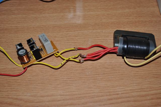
The circuit is composed of two stages: the power oscillator (a Royer topology) and the two multipliers connected in parallel. In between a separation ferrite core transformer is used.
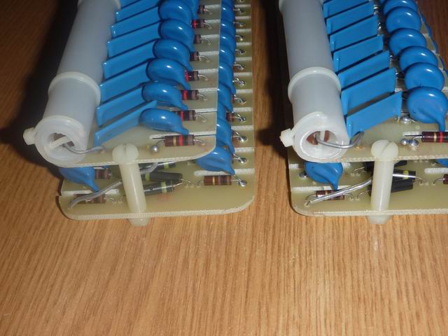
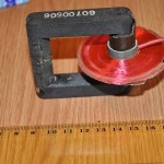
Some pictures with the actual setup:
A few words on glassman multipliers/power supplies are available on the manufacturer website,
“An Overview of Glassman’s Power Supply Technology“.
Some air discharge pictures:
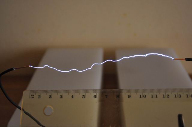


This device is a great tool for physics experiments. Probably you will see it again in some other articles. Some improvements are needed: an enclosure for the two multipliers and driver, voltage instruments (there is already a capacitive+resistive divider to be used for that purpose), current used, etc.
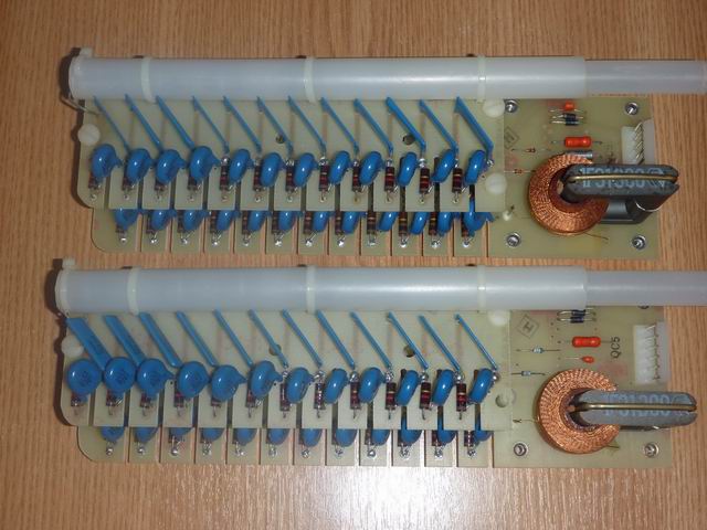
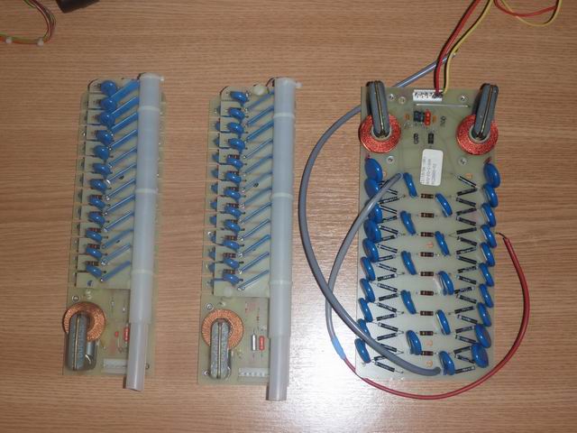
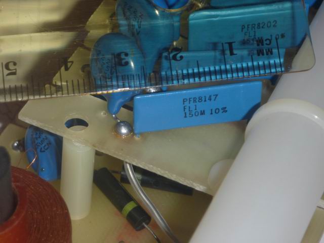
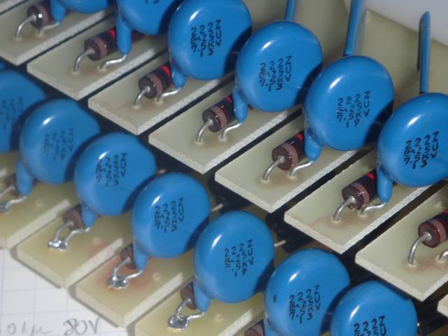
A few pictures with the Glassman multipliers, used in this high voltage power supply:


hey,good blog its great to see other people interested in this stuff. I’ve also built a marx generator capable of 50kv+. I will post it on my blog as soon as i take some good pictures, well check it out if you want, http://frogshvpage.blogspot.com
Cheers,
OK Chris, looking forward to it.
Where do you get the flyback transformers seen in the photos? What’s unique about them is that you can actually see the wire within the secondary winding.
hi Gerry. Those flyback secondaries are manufactured by glassman. Old TV’s also had this kind of flyback transformer, I managed to find one once. You can try building your own, see: http://www.pocketmagic.net/?p=1913
Hey , Radu , keep up this good work, you have a nice blog over here with much good information! When you post some new stuff, I’ll visit your blog again.
Hi Radu, I cannot get a clear copy of your circuit diagram when I increase the size, is it possible that you could email me a copy? I really like the way this looks. Thanks
John McFarlane
@John, try again now.
Hello Radu, Your diy high voltage is the closest I’ve come to seeing something that meets the needs I’m looking for. To activate PVDF as a piezoelectric material it needs exposure to an electric field of 20MV/m, 20 MEGAvolts/m. A 100 kV potential across 0.5 cm would do the job. I’m not an electrician but understand the basics and would like to correspond with regards to building such a device but could not find an email on your site.
Salut :). Frumoasa jucarie bravo !!! , imi poti spune si mie te rog ce diode si condensatori ai folosit in
multiplicatoare ? Voi fi multumit daca obtin 70KV
O zi frumoasa !
Hi 🙂 Nice toy, well done !!! Can you say me please what type diode and capacitors have you used in multiplicators ?
I will so glad if obtain 70 Kv
Have a nice day !
Hi Allez, the multipliers were from Glassman high voltage supplies. I didn’t make those. Instead see my 50KV supply, where I’ve built everything from scratch. There you’ll find details on the caps and diodes.
hi there, I’m looking at building a circuit similar to this using two of my own custom wound flybacks, hoping to bump this up to near 300KV.
I’m just a little confused as to why there’s a capacitive/ resistive divider in this circuit? what benefit does it bring?
I’m also a little unsure about why the caps are only rated for 7.5KV?
and what would you suggest for the diodes in such an application?
Finally, why does the video take a while before arcing begins, then is almost continuous?
sorry for all the questions!!
Joe
The capacitive / resistive divider, connected to pin 4, is for measuring the output voltage.
The 7.5KV capacitor rating are just the manufacturer’s choice, feel free to use caps of higher voltage to match your flyback output.
The diodes are the most vulnerable here, so choose the best you can for this application.
The video starts like that because I was using a regulated variable supply, and I used a pot to push up the input voltage.
please you will have a schematic of an electrostatic painting machine?
Hello my Friend.
When I was apprenticed at a british Telecom radio station, we had from time to time rebuild the power output valves of the transmitters. Once complete, we would evacuate the glass case and then use a very high voltage generator that looked a bit like Flash Gordons spaceship, it had a 4″ length of rubber/cotton covered cable and a brass ball on the end. When set to full voltage, sparks would emit from the ball in to the air. To test the vacuum we would touch the glass case and if the sparks were visible inside, the vacuum was not sufficient/complete.
From time to time we would have local groups visit for a tour. We would leave this tool on the bench set to full voltage and while talking, usually about high voltage floating around the site, we would touch the brass ball and then hold a finger up, sparks would emit from our fingers and scare the bejeesus out of the group. We were limited to the amount of time you could do this mainly because of the hot spot but it was a brilliant trick.
Is there any way I could make a modern, compact version of this ?
Cheers.
Jerry.
@Carlos, I know very little about painting, but feel free to contribute with ideas if you wish.
@Jerry, there sure is, what you need is a high frequency, low current, high voltage generator, and the perfect candidate for that is… a Tesla Coil. See the following project’s I’ve built, you might find them interesting: http://www.pocketmagic.net/?s=tesla+coil
Hello friend
what is the value of the capacitorC3 because I cant see it in the diagram and the capacitor C2 is 0.01 uF?
THANK YOU