
 |
I’ve learned a few things about flyback transformers, after my previous two articles on this topic: Homemade Flyback secondary -2- Homemade Flyback secondary To design a good secondary coil a few basic things should be considered: |
So I had to come with a better idea, to create an indestructible flyback secondary, that would both perform well, and last forever no matter how much stress I put on it. Here’s what I came up with:
 |
 |
 |
 |
 |
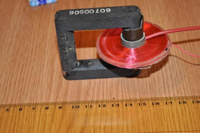
The new design uses a disc shaped flyback secondary. This way the insulation problem is solved, without too much work in separating each layer. The inter-layer capacitance is also decreased. The first turns are at the maximum possible distance from the final turns, a good thing for high difference potentials.
How to build (a good) Flyback seconday
You will need:

|
– PVC pipe, wide enough to fit the Ferrite core. The pipe’s internal diameter should match the feritte’s external diameter, so it would be fixed on it. – Epoxy – you will need like 20+20g for a 6cm diameter disc flyback like the one pictured above – Wire for winding the secondary – Small DC motor with variable power supply to adjust the motor speed – cardboard – green house foil (I used UV resistant foil) – polyethylene plastic sheet – paper glue (not very strong!) |
Step 1
Start by drawing two circles on the cardboard. The diameter you choose will be the diameter of your flyback disc. Mine were 6 cm diameter (check your ferrite core first, make sure the secondary disc will fit). Inside each circle, draw a smaller concentric circle, with the diameter a little bit smaller then the exterior diameter of your PVC pipe (you’ll need to force fit the cardboard discs on the PVC pipe). Put some paper glue over the cardboard inside the two circles. You can apply glue only over the circumference. Cover the cardboard with a piece of green house foil, make sure it adheres to the glued area (press it carefully):

Step 2
Cut the two discs out, make sure the foil remains fixed on the cardboard (the glue will hold it but won’t stick to it), then using a sharp cutter, cut out the inner circle. Take your PVC pipe and carefully force it through the discs. Make sure the two discs are facing each other with the foil covered face. In between you will form the secondary disc, using wire and epoxy, and at the end you will need to take the cardboard discs apart. The green house foil will let you do this easily, since epoxy doesn’t adhere to it:
 |
 |
 |
 |
Make sure the two discs are at maximum 3mm apart! The space between must be 3mm or less. Use a small object of this size, and move it all around the space between the discs, to check the distance is uniform. When the pipe is force trough the discs a small paper formation will be pushed out at the exit end. This will help making the discs fixed on the pipe so they will not move while winding. So be careful not to make the inner circle too wide!
Step 3
Take the DC motor and cover the axis with some rubber tubing, tape or whatever you will need to increase the axis diameter to fit the PVC pipe. you will use it to rotate the PVC pipe with discs, to make the coil easily.
Step 4
Take the end of the winding wire, between the two discs, and force it out at the bottom, near the PVC pipe. You can use a needle to make some room first. You can also connect a ticker insulated wire to the thin one, and take that out. This will be the first connector of your flyback (the low potential one). Put the PVC pipe with discs and wire on the DC motor axis, add some epoxy over the Pipe and wire (between the discs) . Do not worry if the epoxy remains between the discs and doesn’t get down to the Pipe surface: when winding, the wire will take it down exactly where we need it. Make sure you use plenty of epoxy, and move fast, so it doesn’t solidify before you manage to make the coil turns:
 |
 |
 |
In one hand hold the motor and with a finger break the rotation as needed. With the other hand adjust the motor’s voltage and then hold the wire and make sure it goes in between the discs. Release the finger break. Make sure the speed is not too high, or it could break your wire.
Make sure the forming coil is always covered by a small quantity of epoxy. So from time to time, stop the motor, and add epoxy, then continue.
Try to wind the coil uniformly (but at 3 mm gap, this will happen anyway) .
Step 5
When the coil is finished (approaching the 6cm diameter limit), connect the ending wire, and add an extra epoxy layer over the external circumference. Let it dry (in my case it needed 5 hours, read the instructions on your epoxy tubes).
Step 6
Use a toothpick or a similar non metallic sharp tool, to remove the cardboard discs. Just push the toothpick between the cardboard and the green house foil, and both will come out easily. A nice flyback secondary disc consisting of only hardened epoxy and wire remains:
 |
 |
 |
 |
Be careful about these possible mistakes:
I’ve learned them the hard way:
1) Do not make the distance between the cardboard discs bigger then 3 mm! You risk to get turns with high potential difference in close proximity and they will arc, destroying your secondary.
3 mm space with a winding wire of 0.1 – 0.14 mm diameter is perfect.
2) Do not replace the green house foil by paper or other foil the epoxy adheres to. You won’t be able to remove the discs, and the flyback will look bad (but will work ok):

Some ideas
If you have plenty of space on your ferrite core, you can place 2 or 3 such secondary discs and connect them in series, but make sure the starting wire goes to the ending one of the other coil. Also make sure they are winded in the same direction. You can also place high voltage diodes, to put lesser stress on the secondaries and get DC high voltage, like it is done in modern flyback transformers:
 |
 |
For best results, the primary coil should be created as close as possible to the secondary. You could also wind it under the secondary coil.
Good luck with your own!

muy bueno
Excelente tutorial
great work ! thank you …
please a question if possible
– How to calculate the value of the output voltage since we have some informations like number of turns ,diameter of th wire etc….
– how to control the output voltage if possible .
any idea will be helpful thank you very much.
Hi, great work.
This device looks like a Ruhmkhorff pie secondary coil. Would it be made?
Using a lots of that coils for to build a Induction coil sounds me a good idea. What dou you say about isolation?
Thanks
Pingback: High Voltage inverter KIT – PocketMagic