
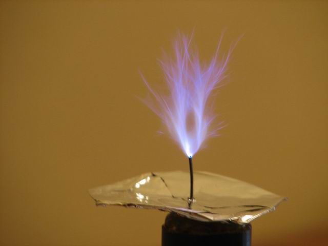
Using a single mosfet (IRFP 460) in an Armstrong oscillator, I was able to obtain my first SSTC “light” , accompanied by a powerful RF field.
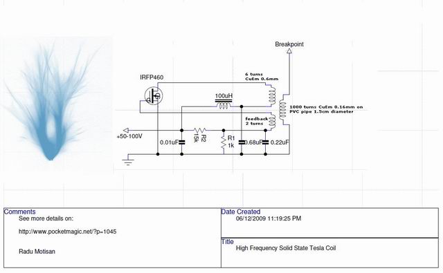
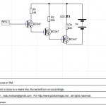
High frequency Solid State Tesla coil circuit:
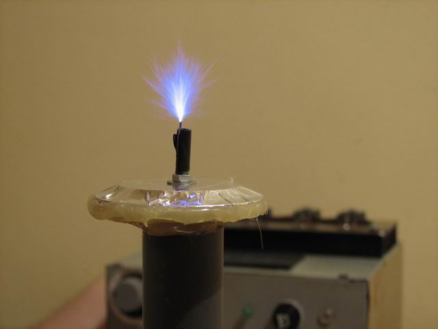
The first tests seemed promising, however the breakout needed to be instantiated manually using a screwdriver:
The video shows the very first tests, without any tweaking. The primary was set at 4 turns. The mosfet was getting hot quite quickly, with 100V input voltage.
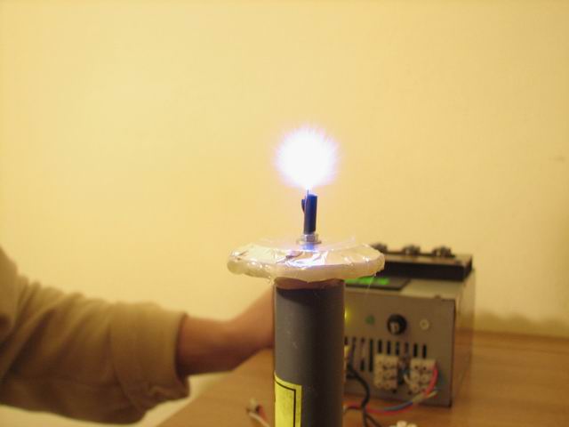
After a few tests, a value of 6 turns for the primary was selected, and a small top load was added. This greatly improved performance.
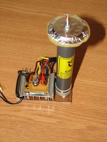
The tesla transformer, consists of a PVC pipe 1.5cm diameter, with the 1000 turns secondary, inserted inside a larger PVC tube of 2.5cm diameter. The primary and the feedback coils are wound on the larger tube at the bottom. A very compact design that also allows the two tubes to slide, so the primary+feedback goes closer or further from the secondary, allowing to tune the resonance in a very convenient way. Also the mosfet was much cooler now.
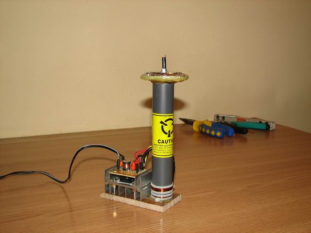
So I’ve packed everything together in a nice compact setup. Here are a few more pictures and videos with the final setup:
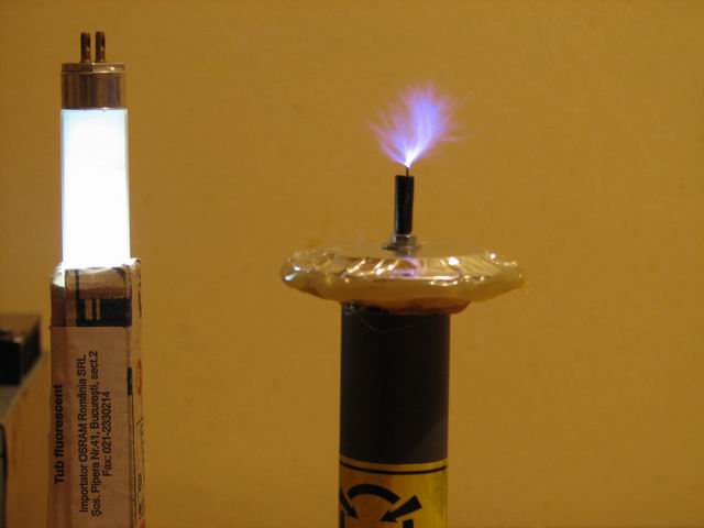
Using the HFSSTC at 50V and then at 100V:
A few pictures with the HFSSTC:

A last video with the HFSSTC with lights turned off
A few things I’ve learned:
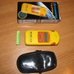
1) The IRFP460 works best. And it must be a quality manufacturer, else it might not work (I’ve tested two mosfets with different manufacturer, and the results were not the same)
2) When winding the tesla transformer, keep in mind that sliding the primary over the secondary helps reaching resonance / better performance / cooler mosfet
3) No breakpoint = dead mosfet – be careful!
4) The device produces strong RF interference, so be careful with all the electronics arround, including the digital camera, your computer, etc . Be careful not to touch any metallic object near the HFSSTC, it will burn you.
5) A topload might help, but better run some tests to see how it goes in your case
6) You will need at least 50V to power this oscillator.
Hope this proves useful,
Radu
Resources:
– my HFSSTC coil on 4HV
Update April 8, 2011
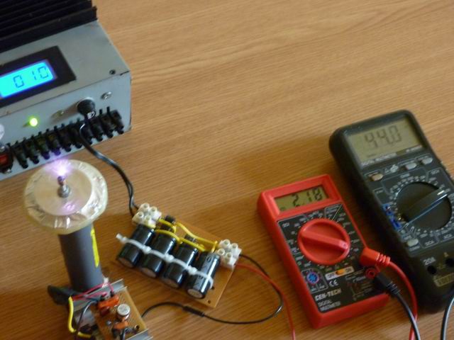
To power this SSTC I’ve used my variable power supply, that also has an alternative current output connector, rated for 24V 10A max. Using a voltage tripler (with caps and diodes) I get 94V DC. When connecting the SSTC, the voltage drops to 44V and the measured current is 2.18A. See the following video:

Here are some variants created by my readers
Spark HFSSTC:
Tio octa HFSSTC:
Jeg’s coil:
This is an absolutely BRILLIANT coil. The simplicity of it is just amazing. I just have one question though. How were you able to get the 50-100 volts required for the circuit and what is the minimum amperage needed?
Thanks
Amindha
Thank you! I didn’t measure the current it uses yet, but will do that soon.
Regarding the 50-100V, I have a power source with a toroidal transorfmer 220V->24V@10Amps max. Instead of the rectifier I’ve used a voltage tripler like this:
http://www.coolcircuit.com/circuit/voltage/vt.GIF
Hi
Thank You so much for the reply. I was able to obtain a dula out put transformer that is able to give me 50volts @2amps and 100v@1amp. I was wondering about the secondary coil. 1.5cm diameter for a secondary seems VERY small. Is this a typo or is it supposed to be this. If so, would i be able to incorporate a larger secondary, for example, a 2-3cm diameter secondary. Would this have a negative affect on the coils’ output?
Thanks
Amindha
Hi Amindha,
My secondary coil was built on a 1.5cm diameter PVC pipe, so no typo here 🙂
I know it’s small, but my goal was to achieve a high frequency coil, so this fits perfectly.
You can try bigger diameters if you have them already built, but if not, I recommend you try something similar to my design, to be sure it works. To good thing is you need very little wire for such a small diameter.
All the bests,
Radu
That is a great, thanks a lot to post this.
i made this circuit and had it working. my Tesla secondary is 445mm tall by 40 mm diameter 0.5 mm wire 447 winds i had very tiny arc and burnt out $70 worth of transistors but they were Chinese would a recovery diode prevent damage or do i need a smaller Tesla coil? trying hard to tune it i will try your design to save money but was curious.
Hi,
First of all I want to say I really like your projects.
I am trying to build a tesla coil also but I am having trouble finding the necessary wire.
Can you tell me please from where did you get the wire for the coils?
Awesome! Thanks for sharing with us. I could not believe my eyes watching the spark from such a small coil …. LOL
Hey, did you measured the resonant frequency? Please let us know the frequency.
Try a smaller tesla transformer. To tune it, try sliding the primary coil up and down over the secondary!
Hi Ionut, thanks. I’m using the wire from the coils of some big relays.
@Anowar, thanks, I will measure it and let you know.
Dear Sir..
Please help me to know what is good name manufacturer sell your mosfet(IRFP460 )
Thank you so much for your time.
Best regards
lam
Hello Iam, there is a seller on Ebay that sells good quality IRFP460:
http://stores.ebay.com/Thai-Shop-Etc
Dear Radu Motisan
First thank you so much for your time help me.
When you have the time please help me to know more:
– your item need how much ampere at 50 volts and 100volt
– when using circuit voltage triple The rated of diode capacitor ( Diode ampere) +(capacitors farad).
– Frequency at item working
Thanks in advance for your time. Sorry for my English
Hey Radu Motisan
I have seen your you tube videos on this.
ive built the circuit and tesla coil, its about 3 inches by 9 inches with 900 Turns.
i have break out nothing as spectacular as yours, it runs around 550 khz if i put on a top load there is no break out even with breakout point
i just see the pruple glow (corona) ontop. have about 120 v input into the circuit. Transistor Over heats, ive tried movin the coil up and down but it gets out of resonance.
Hi CMS, can you post some pictures?
at last a simple schematic for a sstc, could you tell me what the exact values of the caps and resistors are, im a nube at the finer electronics, i built a large spark gap TC but now want something a little smaller and finer. if you can direct me to a schematic that is just as simple to make a larger SSTC, or maybe even an audio modulated sstc.
great little TC
jrr
hi jaydenrr, thanks!
Indeed it’s a simple feedback air transformer, but gives some very good results: like a strong RF field as shown in videos.
The caps values are show in the schematic, their voltage is probably ~250 – 400V , I can’t remember, but I’ll check that and get back to you.
Good luck building your own. When it’s complete, post some pictures here, so I can include them in my article.
great, thanks for the info. cant wait to get started on my own.
Looking forward to seeing it! Good luck
about the voltage of the caps, I’m shopping for the parts and wanted to know if the voltage would affect the circuit significantly does “~250 – 400V” mean it makes no difference as long as its between those two values? i don’t want to get the wrong parts and have parts over heat, explode or anything of the sort. and about the top load, why would the MOSFET blow if there is no break out terminal?
another thing, what are you using for the power supply? i was thinking i would just use a variac and a diode bridge, but it looks like you have a more appropriate setup
jaydenrr, the caps are not critical.
actually a variac and a bridge is better, so go ahead and use that.
I have a 24V AC supply, and using a high current multiplier I got 100V DC. I believe this SSTC can take up to 120V without damaging the components. Make sure you start with 50V when testing and increase the voltage gradually.
Good luck.
about the voltage of the caps, will any value between 250 400v work? im just a little pressed for time because i dont live in the US and these components can be a pain to get or ship to Mexico, so i need to do my shopping while im here.
ty
Yes, between 250 and 400 should be ok . The components I used where not new, they where taken from ATX power supplies.
Last question what wattage and tolerance should the resistors be?
the resistors I’ve used are some cheap components from china. 1/4 watts
now this is the last question, honest. what current rating should the 100uH coil be and what self resonant frequency should it have?
my inductor was really small, probably handling 1A max. I suggest you use a bigger one, it should handle heating much better too.
See this : http://www.pocketmagic.net/wp-content/uploads/2009/12/IMG_8923.JPG
Whats the max size minimum size Coils that can be used with this circuit? max – min resonant frequency?
or does it have to be the exact frequency and size in your setup, how do i vary it for my coil?
i have 11 ” by 3″ around 450-600 Khz res freq.
C, the resonant frequency of this coil is around 4.6MHz . The oscillator circuit might work for your bigger-sized coil but I don’t think you will achieve break-through with that. However the RF field should be detectable using a neon bulb or fluorescent lamp. Good luck
i’ve tried it on a smaller coil around 6″ round 900khz to 1.2 mhz ive gotten break out. but just very small ive tried sliding the secondary up and down but the mosfet still gets quite hot with a heatsink in less than 20-30 seconds
was thinking going bigger would get a bigger breakout? or is the frequency getting to low for breakout ot be achieved whats up with that :S
i do have a flourescent bulb testing the rf field n it lights up
yes I think the key factor to this design is the frequency. You should try to raise it , not the opposite. BTW , can you post a few pics with your design?
so in this case smaller = better lols 😛
i have to get around to that. i had a few pics on my blackberry buts its dead now.. i’ll try to get a pic off the memory card soon
well if thats the key factor i’ll have to rewind a smaller coil.
would u be able to give me any advice into a circuit that would be good to power the 13″ by 3″ tesla coil ive already wound a while back?
i’ve got a pic of the coil and vid. how do i upload it for you to check?
ive gotten it working at 500 khz , made a ordinary incandescent light bulb a plasma ball effect. But only achieving around 1 – 1.5 cm corona air discharge. primary 4 turns
mosfet overheats within 20 seconds with heat sink, ive tried sliding the primary up and down the TC, mosfet still overheats.
post the links as comments (pic on tinypic / vid on youtube)
This is a really interesting driver due to its simplicity. I ordered a few IRFP460’s and im planning on testing it on a whole variety of different secondaries (all which have a resonant frequency of 3-4 MHz).
What really ponders me is why did you use a SGTC-like secondary? Since your secondary is very tall and thin and has a really high number of secondary turns (most HFSSTC’s i’ve seen only have like 200-300 secondary turns) I feel like better performance could be obtained from a shorter and thicker secondary with fewer turns.
Anyways, thanks for the schematic and I will post pictures once I finish building my driver.
@clacid, looking forward to seeing your photos!
The thin/tall secondary I used was what I had at hand at that time. The topload is not needed, but a breaking point is a must.
So your experiments with various secondaries will bring lots of interesting details that other builder will probably find very useful.
Hi Radu,
cool circuit & idea. Got most parts at hand, just a 100%
matching inductor is mising, so – how critical is the 100uH
value of the inductor ?
Hi Spark, none of the components are critical, but changing them can get you into problems obtaining breakthrough.
Built it up and YES – wo. tweaking the inductor is critical –
all I got was a pathetic lil glow :-/
No big deal, as the matching inductor is already on my next
order list 🙂
Oh – to save me some testing – what is the diameter of the
outer tube and what Amps are best for the poer supply.
THX for your hints.
@Spark, I’ve edited the article to add this missing info. Hope this helps – would like to see some pics of your setup.
Hi Radu –
Tweakened the setup a bit aaand – First Light 🙂
Catch was mostly the power supply – while the old one
could supply >= 100V it only gave something like a 2A
Using a 50V/8A and a bigger TopLoad the Goody worked.
First results can be seen here
http://sparky.netai.net/files/SSTC.wmv
Don’t judge the (sloppy) setup too early – all is going
to be neat and tidy as soon as the original parts arrive.
BTW – once completed I would like to present/introduce
this nice circuit with complete documentation at my
forum (www.ultra-voltage.com) – of course with all
Credits & Backlink. Is that OK with you ?
Greetz
Der Spark
Hi Spark,
Nice to see your first results. From the way that fluorescent tube is lit, I’d say you got some strong RF field as well. It is the same in my case, but be careful with electronics that have field-sensitive sensors like touchpads – you can easily destroy them if they are too close to your HFSSTC.
What about the mosfet temperature?
Feel free to post the circuit anywhere you want, I would appreciate if you would include a back-link or credits. BTW, the name of this device is HFSSTC (from high frequency, of course).
Cheers!
Radu
Jup – the Goody sends out a sh*tload of RF. An unshielded
Cheapo DMM becomes useless even at a 1 mtr. distance….
In fact that’s why I moved the whole setup to my kitchen,
as there are no (valueable) electronic devices around :LOL:
At ~10 Minutes FET stays icecold. I will install active
cooling though, esp. as I want to run the setup at the
Target of >= 100V.
THX for yr. permission to post the review. Of course I
will link back and put a notice here once my article is
up.
Greetz
Der Spark
Sounds good! Looking forward to your final variant.
Good luck!
Radu
Hello I have one question regarding this really nice SSTC.
What amperage can I get away with to power it?
I’ve been looking at Variacs(I need to buy some form of PSU) and I’m not sure if 2 amps will cut it or not. If 2 amps won’t work, what do you suggest ?
I know you used 8 amps but I’m somewhat budgeted, the more amperage the more the PSU costs
Hi Josh,
My setup was powered using a 24V AC @10A max, and a multiplier, so the output was 100V DC with a lower current capability.
Using a Variac is the perfect solution, 2Amps is more then you need, but I will measure the current used and the voltage drop and get back to you.
@Josh, I’ve added more details, see the bottom of the article.
According to the update it’s using less then one amp! That’s good for me.
I will look forward to more of your projects as they are interesting to read.
thanks, josh!
Hello! I built the coil that you propose. I use a 100v transformer limited by a resistor at 2 amps and then rectified with a diode bridge. The coil works fine but the spark is not half as big as that of the video samples. Why can it be? From already thank you very much.
Sorry for my bad English. I’m from Argentina and I use the google translator.
@Tio octa, can you post some pictures with your setup? Is your coil similar to mine? Try changing the number of turns in the primary coil.
http://www.youtube.com/watch?v=BjjevdX3hiM&feature=player_embedded
I use 1000 turns of 0.16 cu wire on the secondary (in a 2 cm pvc pipe)
6 turns primary coil 0.6 cu wire
2 turns feedback coil 0.6 cu wire
the 1k ohm resistor that i use in the primary circuit is ceramic and 20w
The inductor that I´ve used consist on 10 turns of 1mm. wire on a computer power supply toroid (because the inductor of 100 uH got fried instantly)
Another question:
The dc of the circuit must be smoothed with a capacitor?
Good question.
My supply for this SSTC uses a voltage tripler , 24V AC 50Hz in, 3 caps 4700uF/50V (if I remember correctly), 6A diodes. So you should also use a smoothing capacitor.
bravo rado!!!!! its possible to make with 3000 turns?
good bye ciao*******
yes but the frequency will be lower
Hey, cool tesla coil. Im going to build my own from your design
I was wondering if I could use 0.1mm copper wire at 1000 turns?
Cheers
yes you can use that, but make sure you keep to the indicated core diameter.
Hi iv ordered all the parts, but the only part I couldn’t get
Was the 15 mm PVC pipe, the closest iv found so far is 20mm
Will that still be alright?
(I just don’t want to wind it all MANUALLY!)
Cheers
” to be wrong
Hello, I was wondering if you were ever able to use the ATTiny processor to change the frequency at which this operates. I am on 4hv, username is 92_foxgt, if you don’t mind shoot me a PM.
hello excellent coil, and I have been trying to make a coil of 1050 turns (2cm diameter PVC tube) enamelled copper wire of 0.17, and slips into a coil with 6 turns (diameter pvc pipe 2.5) enamelled copper wire of 1.02mm ….. I have the IRFP460 transistor, and all connected as shown in the design, just add a diode bridge connected directly, I’m in Colombia to here the connection is 110V-60hz, but when I turn burns 1kohm resistance can be? muchisismo would appreciate the help. regards
Hi!
I tried yesterday to build your device without the secondary, running it at 24V and using an IRF470. I used a 3.3K resistor instead of 1K, because I just didn’t have a big enough 1K resistor around. The primary and feedback coils are rather crude, 5 and 2 turns winded around a used roll of toilet paper.
At first I used a computer power supply. I was working very smoothly, drawing about 100mA and producing about 6-7MHz (jumping up and down, due to the self-resonating unstable capacitance and shaky coils). Then I tried to use a variac with a rectifier, in order to increase the voltage slightly, to 30V. To my great surprise, it blew the 10A fuse inside the variac!
I have no explanation for this weird behavior. The current, apparently, suddenly jumped up by two orders of magnitude. Did you experience anything like that? The transistor did not get shorted. It’s still alive, I checked it out.
I can only tell you that you’ll need to spend some time tweaking this rather unstable design, but once you get it to work it will perform nicely. After all it is a very simple design and that is its main advantage.
I didn’t get the current issue you’re describing ,. Would love to see your work, can you send me pics with your variant?
I will send you the pics, but I will try to design an even more minimalistic RF generator. I got just now a pack of fuses and I have a whole bunch of MOSFETS to kill. 🙂
ok, good luck with that 🙂
Hi,
What is the purpose of the 0.01uF and 0.22uF capacitors? Am I right in thinking the 0.68uF connected between the powered side of the coil and ground is the LC tank capacitor?
I made the exact circuit, but nothing happens, no sparks at all 🙁 But there is voltage drop on my voltage trippler… what could be the problem?
Miloš, try adjusting the feedback coil. You need to do a little bit of tweaking before you can get it to oscillate, but once you do that it will run stable.
Mosfet does not get hot at all, and it’s just from the store… could it be dead?
Okay, I got the first sparks! But only few millimeters 🙁 😀 My secondary is 8,6 cm tall 3,3 cm wide, 0,2 mm wire. Primary is 4T and feedback is 2T, but the IRFP460 does not get heated at all, and I’m driving the circuit on 130V DC… Everything else is same as in your circuit… Any suggestions?
Did you try draw some arc from your coil?Is it like high power flyback arc?
@James, probably it is possible to draw arcs. I don’t remember.
Hi!Radu Motisan
Thanks for sharing with us.
100v DC waveform requirements? Can with 100v pulsating DC?
Sorry my English is not good.
I’m from China and I use Google Translate.
Hello Radu
Can you give some extra info for coil building.
Feedbak coil must be in opposite phase like in other oscillator circuits?
Distance from primary to feedbak windings?They are near close or some,few mm between?
Some detalied photo of coil with few addnotation (which end wire where is connected) would be very helpfull.
What about higher frequency?How frequncy affect SSTC? Increasing frequency will increase sparks?
As a note,you may see on various site some hacking device,who can light a flourescent tube,based on 2SC2078.I calculated from their info thats working somewhere at 40MHz.
Is possible from a derivation of their schematic to build a SSTC at such higher frequency?
Salut Gabi 🙂
There isn’t much to say, best thing is to do a little research yourself, for the optimum configuration. The interesting fact is the coils can be moved one against the other to obtain the resonant coupling.
Regarding the feedback coil, it is very similar to other oscillator circuits (and the working principle is the same), after all this is nothing but an Armstrong feedback oscillator.
To increase the frequency, one way to go is to change the number of turns in the secondary.
Have you started building your own? I look forward to your results. Should you have any other questions, feel free to post them here
hi i have done successfully coil but wondered how it could increase the spark to make it as in their last videos.Por which is now as in his first video.
From already thank you very much
@Carlos: increase the input voltage.
ok, I’ll try.
had left with 24v the input because I was afraid of burning the IRFP460
Can you explain the MOSFET can survive from 100V? 😀
Hi,
do you use a AC oder a DC power supply to power the cascade?
How big are the capacitors used there?
Thx for your help
Hi Radu.. What if the values
of the capacitors are
superior?
Hi Radu.. I can replace the IRFP460 for IRFP450??
@julian: Yes, I think some of the guys commenting above already tried that. Go ahead and see how it goes, experimenting is fun!
Pingback: High Voltage Power supplies - PocketMagic
i am unable to start the coil does winding direction of secondry coil matters
ien
one of my friends is running same of your of your circuit at 27v 3amp transformer with good spark as yours .
kindly suggest how to start i did copy my friends circuit but still not able to start
please provide 24V AC @10A max, and a multiplier schematic
Sir please please reply and help me are bothe thr coils I. San primary 6 turns and feedback 2 turns are wound in same direction please help me