
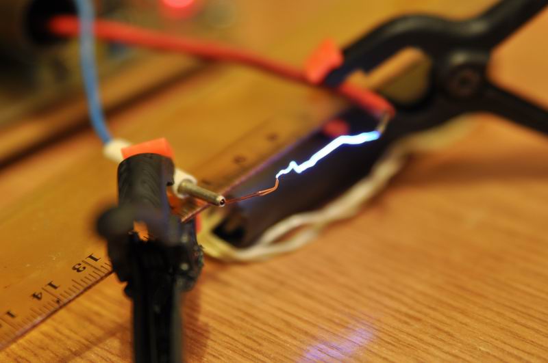
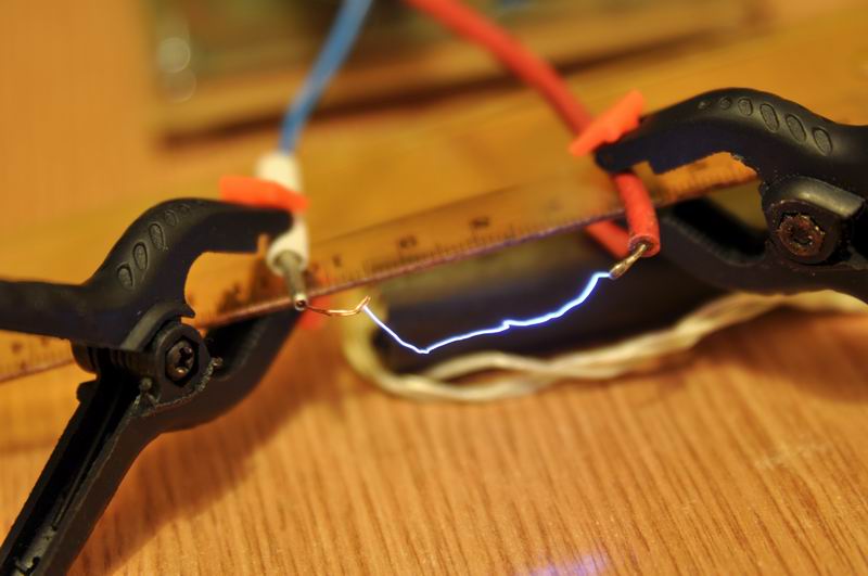
I built my first electric fence circuit back in 2011, to protect the perimeter of a tent from bears. The circuit still works today and gives a very good performance. A few changes have been made like adding the neon bulb protection for induction coil spikes sent back in the primary circuit.
The circuit runs on 12V (batteries), making this a very portable fence energizer solution. It uses 2x 555 timers, one runs in astable mode and is used to generate the frequency interval, while the second one controls the pulse length and so the output voltage. A calculator for the 555 timers can be found here.
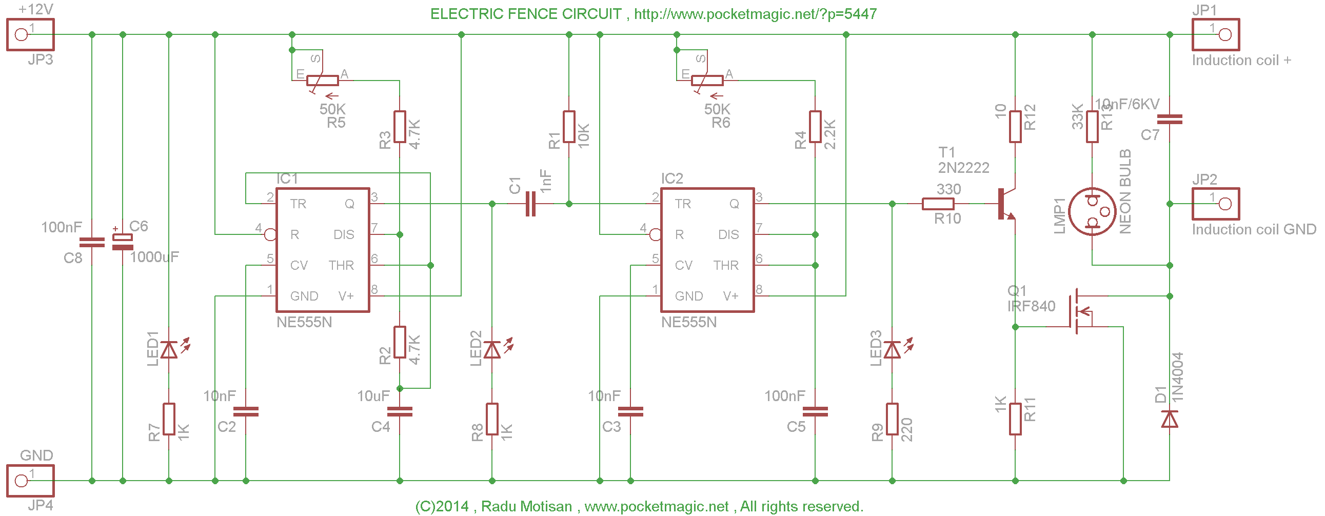
The updated circuit diagram for this version of the circuit is available:
Here are the Eagle files, with both the SCH and the PCB layout: fence-4.3-orig
Miniaturized version
Thanks to SMD components and various timer alternatives, such as the double timer 556, we can shrink this circuit even further, without making any compromises. Here is an improved version that I’ve just designed and tested with excellent results:

The circuit diagram:
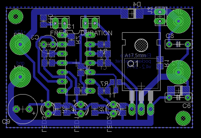
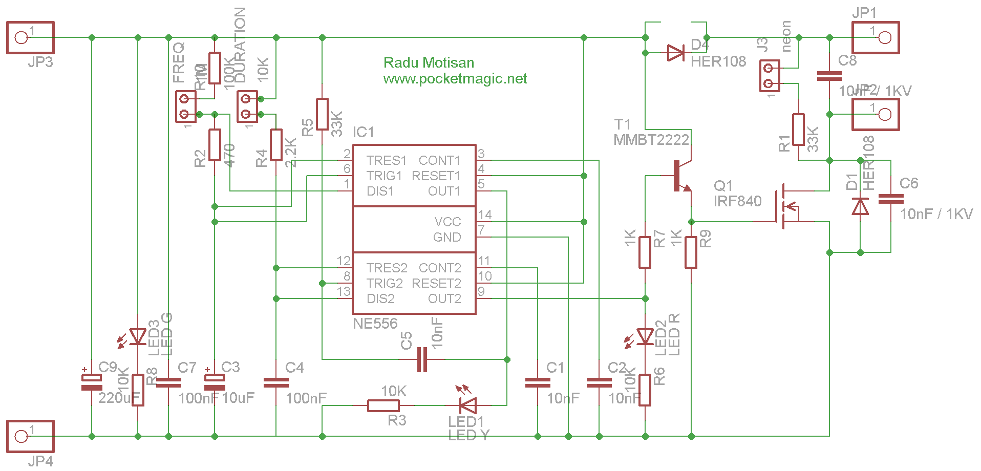
The eagle files: fence-4.2
Both the designs can operate on battery and have low power consumption.
Does it work against bears?
This circuit was not tested against bears nor other animals, but given it’s ratings it would surely create huge amounts of pain. Here is a demo video showing a commercial unit that does work:


Hi, really interesting circuit – I am just in the process of making the PCB and assembling this. Just one question – what is the specification of the neon bulb? Will a standard 240V item suffice? Thanks
Yes a standard neon bulb is ok. The idea is it needs to fire below the transistor’s maximum ratings. 240V should be ok.
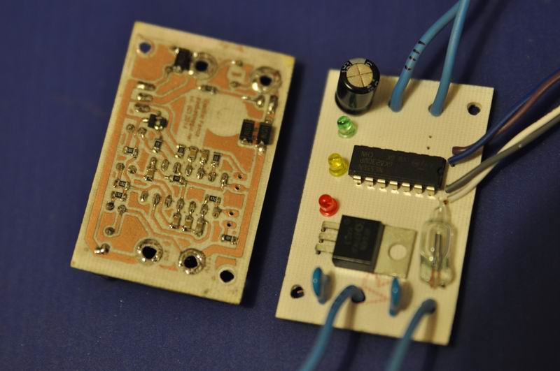
Dear Radu Motisan, I am not clear about the 2nd photograph which shows 14 pin IC where as you are using 8 pin 555. Can you please explain? Thanks!
@Suresh, there are two circuit diagrams. First uses 2×555, the second uses 1×556
Fence 4-2 uses 1×556, and Fence 4-3 uses 2×555 . You have SCH and PCB eagle files for both. If you build it, send me a few photos with your construction. My mail is under “About” in the top menu.
Radu Motisan, Thanks for your clarification. IRF 840 drain to be connected to -ve terminal of coil? Can this circuit run on 6V4.5A battery?Any heat sink is required for IRF840? Can 2N2222 be replaced by any other transistor as it is not available. Suresh
@Suresh yes to all your questions above, except: no heatsink required for the power transistor and if you go for 6V most likely you will get a smaller spark.
Buna ziua
Domnu Radu, in prima schema LEDurile sunt desenate pe dos
In rest,chestia e foarte OK alimentata la 12V si cu o bobina de VW
Jur ca un contact cu chestia doare mai tare ca bataia
pentru comutatie am folosit un singur IGBT in capsula TO220 pentru ca esentiala e viteza de rupere a circuitului primar al bobinei (asta o stiu de cind faceam aprindere pentru Dacia, Oltcit si alte dihanii, numai ca atunci foloseam BUW24)
Foarte tare site-ul
da-i inainte! Felicitari si ‘succesuri’!
Multumesc, Dorin. Ce tip de IGBT ai folosit? Am sa corectez schema pentru greseala cu ledurile in curand. In articolul asta sunt doua scheme postate, prima cu 2×555, si a doua cu 1×556.
Hi, nice circuit !
I want to build it too, but I dont have any induction coils. So my question is, if it is possible to exchange the the coil with a trafo. For example Primary 12V and secondary 230V ?
you can, but such a transformer will break easily, as its primary was not designed to withstand the high voltage.
Okay, thank you very much !
Do you know other opportunities to produce high voltage without a coil ?
Sure, see my other posts on this blog: http://www.pocketmagic.net/category/hardware/high-voltage , especially the “High voltage power supplies”
Thanks a lot !!! 🙂
Hello. I built the “Electric Fence v 1.0” and work as well, but i see you make a batter version and i want build the new version for private. I want ask to you send me accurate parts list if possible. And 6kv capacitor instead of 3kv capacitor is good?
Hi again,
I made your first electric fence (2011) and it work´s like a charm…. with good 2 cm´s sparks.
But when I connect it to the power supply, I am getting some small shocks through the alligator clips that go to the 12v battery.
Will a neon bulb fix this issue….or other component will do the trick….and if so, where to place it..???
Best regards
Nezocas
Radu Motisan
Thanks for this project.
I was wondering if at all you can suggest some modification for this electric fence project to use just ordinary transformers instead of a coil..
and
BT152 Thyristor instead of the transistors.
again thanks for everything..
Mubaira
Buna Radu !
Am realizat circuitul tau din 2011 , de care sunt multumit , iar recent l-am realizat si acesta , cu 2×555 , dar am o problema , LED-urile nu palpaie ci , stau pornite . Inca nu am reusit sa-i dau de capat dar voi incerca. Ceea ce vreau sa te intreb daca ai patito si tu , si ce solutie ai urma ? Multumesc si mult succes in continuare !
salut Andrei. Mie mi-a mers ok. Daca temporizarea nu e ok, verifica condensatorii si rezistentele conectate la 555. Cand am ales valorile am facut calculele si ar trebui sa fie ok.
Hi Radu What is the specification of induction coil?
Hi Radu ..
1.what is the output energy of this circuit?
2.what is the maximum area/(length of wire) it can support?
3.What modifications do I need to do in order to increase the coverage area of electric fence?for example how to increase the maximum out put energy?
Hi,
Can you post a parts list with required voltage ratings for the miniature version? The schematic does not have a list.
Hi, I’m making electric fence, second version for my final project in school. Can you please tell me which LED is which colour and what they represent.
Have a nice day,
Miha
?? HEY CAN WE USE IT AS A ELECTRIC TASER ?
WHAT IF WE INCREASE ITS POWER UP TO 20 KV
N DO THE CIRCUIT WILL BEAR IT ??
Would you sell a kit or a made board?
Hi Radu.
My problem is monkeys.
I live in Thailand .
Would you sell a kit or a made board suitable for my application?
Cheers
Graham
Cum pot intra in posesia unui generator construit si functional?
@Paul & @Graham,
I have no kits available for sell, instead I provided all construction details so those of you interested can build their own.
If for some whatever reason that doesn’t work for you, I might be able to help and build the circuit for you. Drop me a mail (my address is under About section).
@Corneliu v. raspunsul pentru Paul si Graham.
Hello, would it be possible to email me a parts list for both the 4.2 and 4.3 version? Thanks.
Hi
I want to try to build after your plan. But do you have parts list? so Im sure I get all I need.
Best regards
Halvard
Hi Halvard,
You can open the schematics in Eagle, and export the BOM list if that is what you need, but all the components are visible in the schematics already. Also feel free to ask me if you are unsure about anything.
Radu
What kind of resistor is R6?
Is R5 and R6 pot meters?
Hi, yes, R5 and R6 are pots.
can you please explain the working of the above circuit…
Hi Radu,
Greetings from Australia, I have built this circuit on a breadboard and am in the process of converting it to a pcb. All works well except I cannot get the neon to fire have tried different bulbs, the only other thing that I have different is the mosfet using a IRFPC50. Could you suggest a correction or a work around for the neon?
Regards
Geoff
The neon is a high voltage spike back protection. The less it fires, the better.
Hi Radu,
Thank you for the fence ckt. May i know the length of fence wire it can support sufficiently? OR may i get the joule vale?
Buna,
Am realizat si eu schema cu 2×555 si nu palpaie doar becul galben,cel rosu nimic.Cel verde indica ca este alimentat circuitul.Care ar fi problema?
Probabil o greseala in realizare sau piese defecte.
Hello
very nice project…
but i have a problem with irf480 witch get very hot, smoking and stop working…i put a heat sink, nothing better…
power consumption of equipment is 1.5A when i measure with Ammeter
Do you know what could be the problem?
Hello,
i built this circuit but i get sparks of very high frequency, almost constant. I used components as specified, what could be the problem? I did not use a battery as a power suppy but an old atx,
there must be an error in your circuit. Double check . Triple check. check again.
Thank you, you were right but now I have another problem. It works fine for a while, but then sudenly N555 timer blows (for example a few days ago it worked for hours, but then two days ago, the moment I turned it on the timer exploded), sometimes just one, then both. I am sorry for bothering you, but I hope that you have some suggestions.
hello I’m putting the circuit in version 4.3, I have two questions:
1. power supply 12v few amps required for the circuit work well?
2. achievement not get Condenser 10nF to 6KV, I can use of 10nF to 3KV?
1. 1-2amps are enough (the consumption is low)
2. Yes.
Hi radu I’m sorry to bother you but I’m trying to make the first version you did and I was wondering which capacitors have to be electrolytic condensers or if I can use ceramic capacitors for all of them except the one that is polarized , if you can email me a part list my email is josepedrozermeno@hotmail.com. Thank you greetings from Mexico.
Hi again Jan other question in case the have to be electrlitic condensers could you tell me what voltage will the capacitors be thank you.
Hello Jose, these circuits are very simple, and the components are not critical (except the timing resistors / capacitors for the 555, where you simply need to respect the values given). Feel free to change and experiment! Have fun!
hey Radu, have built the version of your project but I have failed to produce the sparks from the coil. if possible, tell me the exact way how connect the wires coming to and from the ignition coil. I will be grateful for your assistance on my email; symnkc6@gmail.com
thanx
hey Radu, is it possible to use ceramic capacitors instead of electrolyte at pin 5 of both timers and pin 3 of the astable. have failed to get electrolyte capacitors of 0.01 & 0.001uF on market
@Simon, Yes
hello Radu i built a copy of your circuit and it works perfectly but it doesn’t give such a big spark it only makes a 0.5 cm spark what can i do to make it as big as the one you show in the video? would it be a mistake in my circuit?
Hello Radu.Great circuit I would like to build it two questions 1. do you sell a kit or a circuit board and 2. does the cap across the coil have to be 3kv would 400v do?
thanking you
Hello Pauric, I’ll be able to sell PCBs some soon. T/hanks for asking.
can you please explain the circuit lil. bit?
Hello Radu. I built a copy and it works fine i can send you a video or pics if you want but i feel that the spark isn´t strong enough so i would like to put a multiplier at the hv output to make it higher. What should be the values of the diodes and the capacitors to make it? Please reply me as soon as possible. Cheers.
Thank you Radu,put my name for 2 I always make a mess of the first one The 556 one looks very neat and tidy One more question what is the purpose of the Cap across the primary of the coil? does it take the place of condenser in the car ign.increase the voltage /current??You don’t use it in your first one
Thanking you
Pauric
Hi Dadu
Have you got around to making the PCB’s yet? I am waiting for them hoping they will be available soon I have got my hands on a coil from an electronic ign would that do very low resistance
regards
Pauric
Hi. I’m looking for a 12v electric fence style charger which has a common ground. The purpose of this would be to protect my van when I’m parked in bear country. All the commercial circuits I’ve found out do not have a common ground which would mean I would have to disconnect the ground before turning them on (which is time consuming and a pain in the butt). Ideally, a large charge would be built up and recharged when discharged. In some campsites bears cause hundreds of thousands of dollars in damage annually, and removing all food is no guarantee they won’t open your car like a tin foil wrapped burrito.
I would expect the paint on the van to insulate the charge quite a bit, only providing a shock when some animal is already in the process of f-ing my stuff up, so I have no problem using a high voltage setup.
respected sir
i have made this circuit and its work well and good
but hear is a problem
when i connect it with 12v 90amp battery the mosfet irf840 is gating very hot and in just a second it fuse
so please help me what to do???
Hey mate awesome project, can you please send a detailed parts list. Or as mentioned above if you could sell the kits I am sure you could make some good extra coin. I know a lot of people who would buy them, as I live in a rural area and everyone has electric fences for stock. Thanks
Hi Radu.
Thanks for posting your circuit. I want to build one but I am trying to understand it so it works first time for me! One thing I’m not sure about is the AC coupling to the trigger for the second (pulse-duration) timer. Is it true that a rising edge on the output of the first timer (the one that sets the frequency) will produce a voltage spike of 24 V at the trigger of the second? If that’s the case, it seems to exceed the maximum input rating (Vcc) – albeit fleetingly. Perhaps I am missing something or perhaps the short duration makes it OK …
Regards,
Richard
In second version of ckt. Right side two terminal. First is induction coil and second is their ground.. Which type induction coli I meam parameters… Explain me please..
Hi
Nice circuit. I made the second electric fence and it work fine!!!
Here is a photo: https://postimg.org/image/8iwjtqhjd/
And here is a video: https://youtu.be/RmslwFgi1uw
thank you for your sharing