
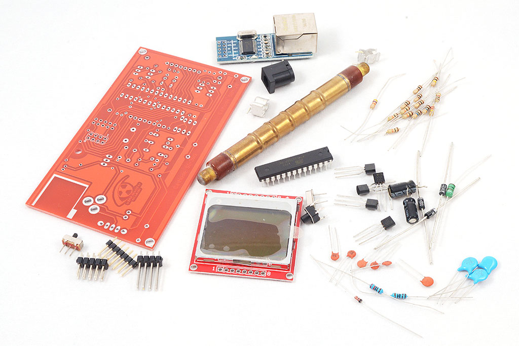
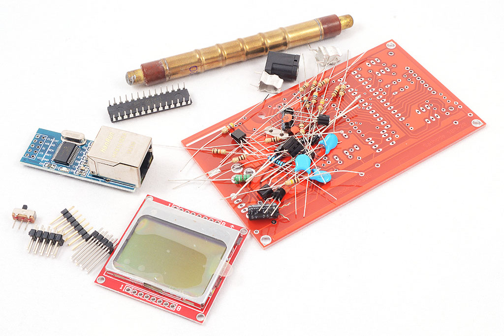
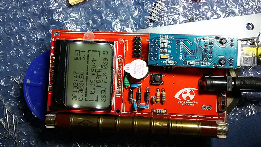
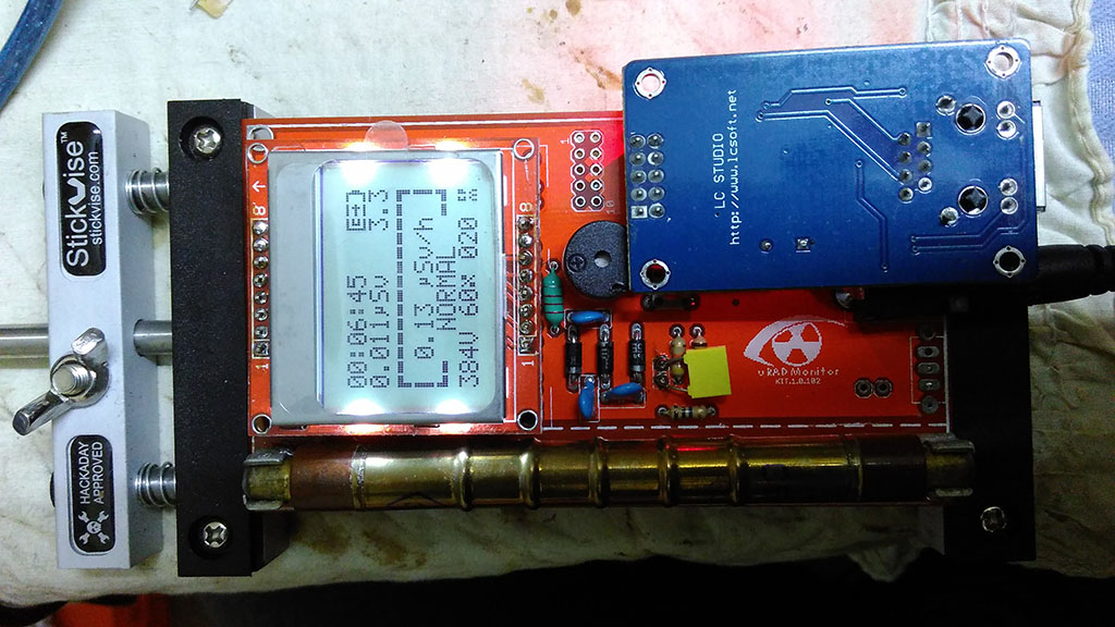
This is an Open Source Digital Radiation Dosimeter, that can be used both as a portable detector, but also as a monitoring station to upload readings to the uRADMonitor network.
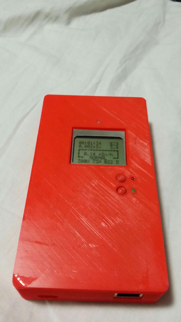
This project is an update to the previous Geiger Counter Kit 1.0. When used as a portable detector, readings are displayed on the LCD. There is also a speaker that beeps on radiation events or is used to sound an alarm for higher readings. When used as a monitoring station (uRADMonitor KIT1), an ENC28J60 Ethernet module must be plugged in for Internet connectivity, to allow it to function as an automated detector, that doesn’t need a separate computer to send the readings to the uRADMonitor network.
Features:
Since this is an update, most of the features were already covered in the original article and the presentation video.
What’s new in 1.1 is that this revision replaces the ferrite transformer in the high voltage inverter, with a ferrite choke circuit, so the complicated part of building the custom transformer is gone. You can build this using shelf components, and the Gerbers files for making the PCBs are also included. Just send the gerbers to your favorite PCB manufacturer, get the BOM and start soldering. With just a couple of components, you’ll have an excellent dosimeter of wonderful performance.
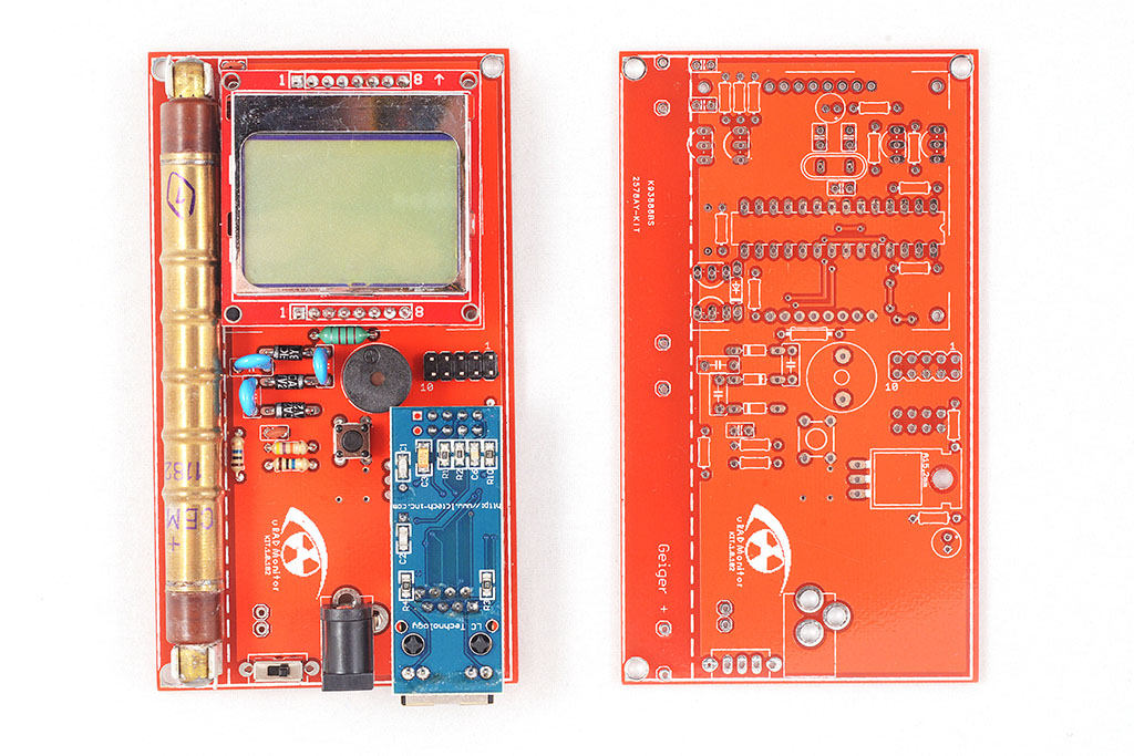
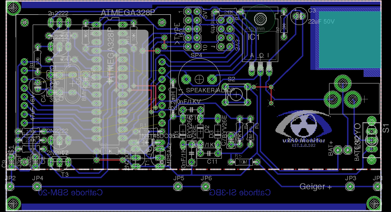
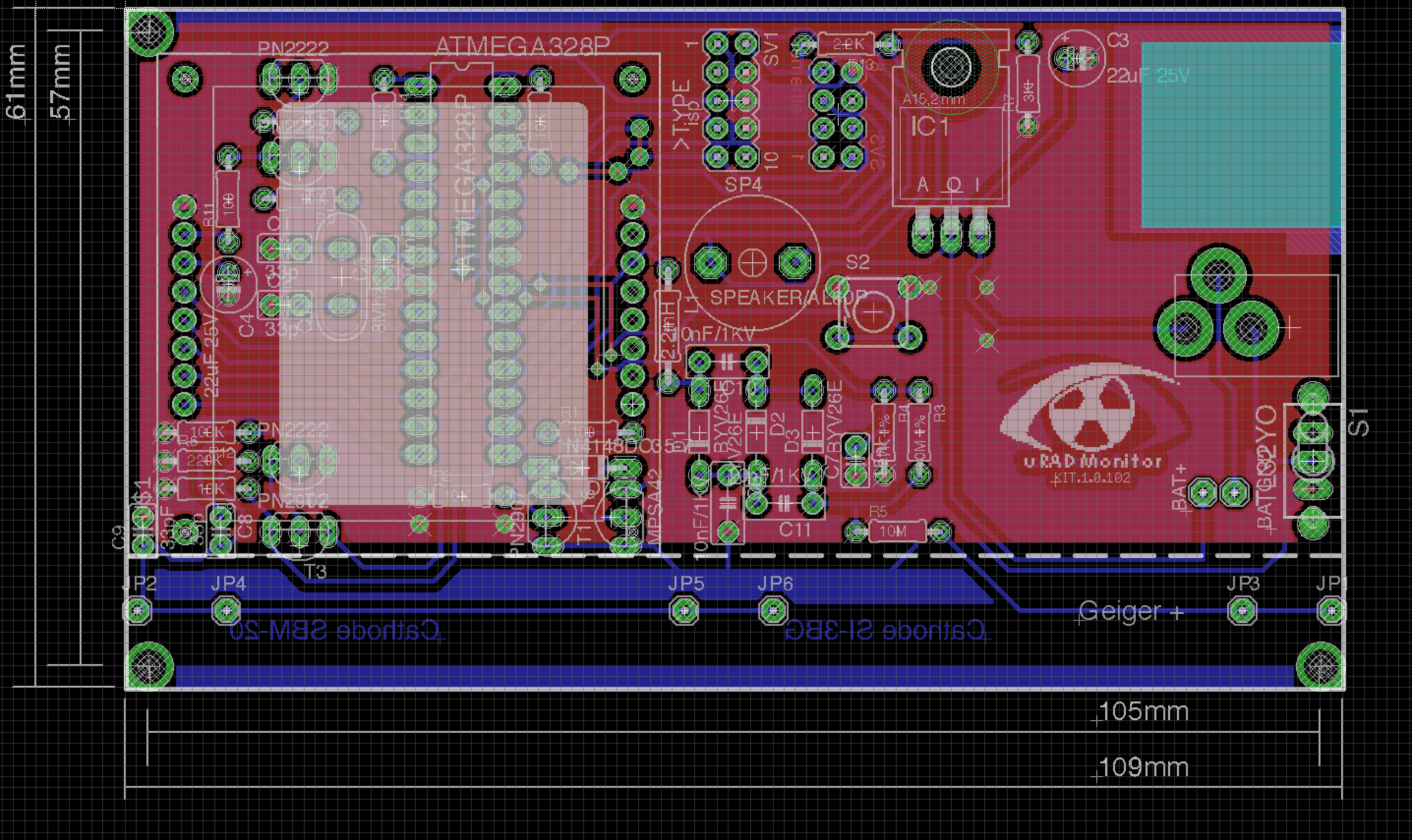
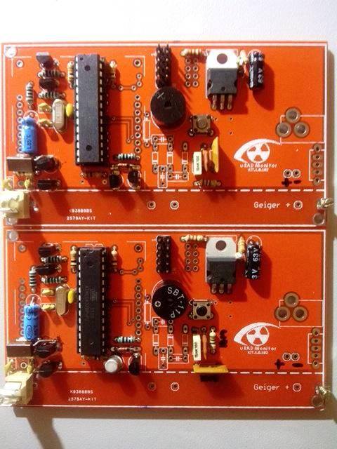
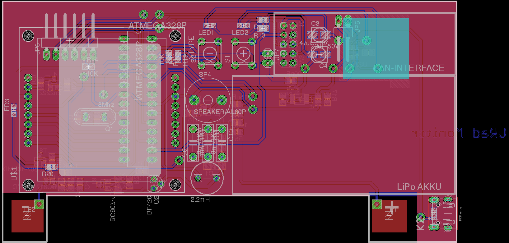
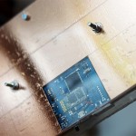
There’s a slot to mount a SBM-20 Geiger tube, a connector for the Ethernet module and one for the Nokia 5110 LCD screen. Both the LCD and the Ethernet adapter can be removed, allowing you to configure the final device: make that a portable dosimeter, a monitoring station or both. A speaker provides audible signals, including clicks and alarm, and a push button permits user interaction with the software. There are two pins at the bottom side that can be used to connect a 3V battery (two AA in series) or the unit can be powered using the DC connector, via a LM317 regulator and then it takes in any voltage in the 5-9V interval. The entire board runs on 3V, and the high voltage inverter boosts that up to 380V, configurable in software up to 600V if a different Geiger tube needs to be used.
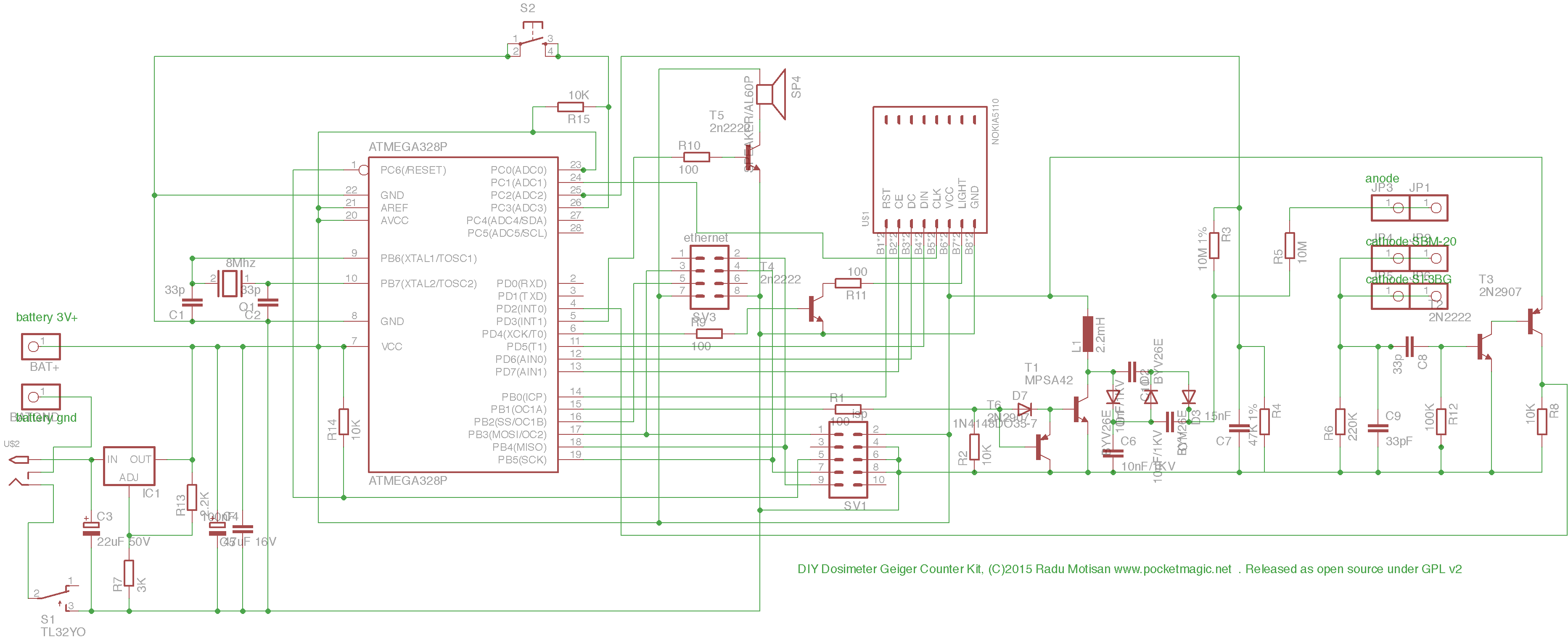
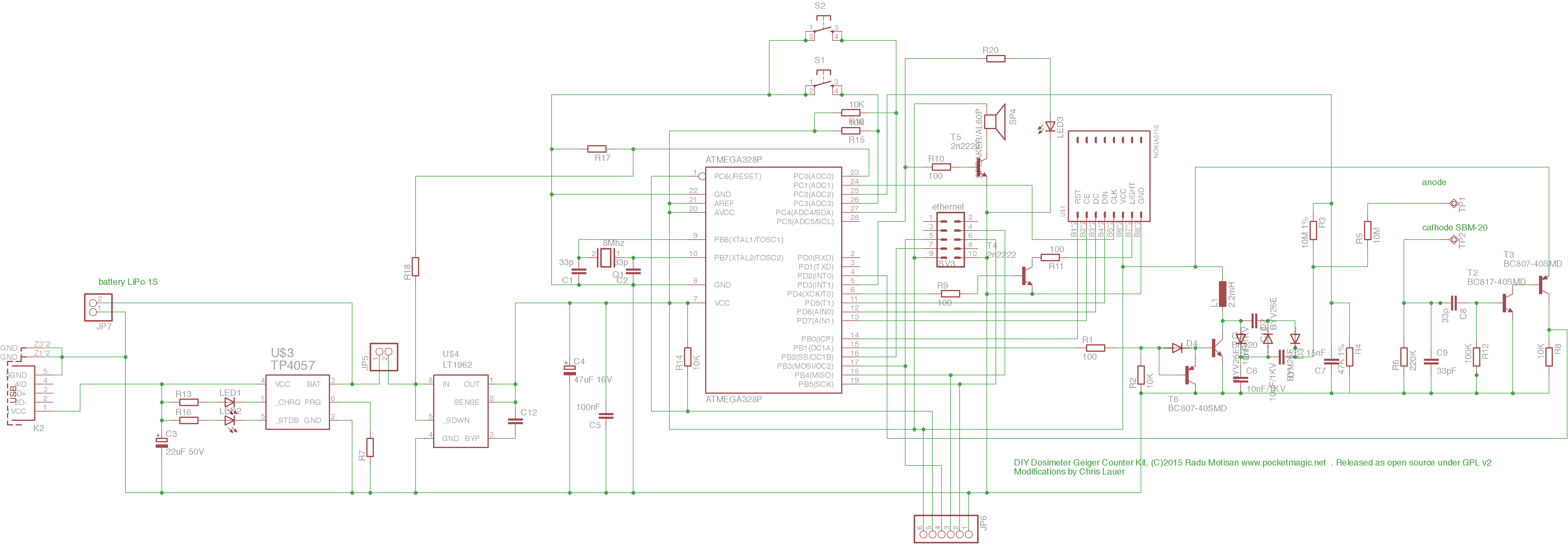
The circuit

Released as Open Source
uRADMonitor KIT1.1 is released as Open Source, under GPL v2. It includes the circuit diagram as Eagle files, and the firmware source code. To review the GPL v2 license, click here.
Code is on Github, or a first release can be downloaded here.
The PCB as PDF is available here: KIT1.1.102_PDF
Precompiled firmware
For those of you that want to avoid the hassle of downloading and compiling the code, I have included the compiled code as well: firmware. There are two hex files inside:
One variant is a simple, offline code that works without the Ethernet module: uradmonitor-kit1-local.hex while the second adds support for Ethernet as well: uradmonitor-kit1-eth.hex . Some instructions on how to burn a hex firmware file to the microcontroller are provided here. To correctly burn any of the two hex files into your microcontroller, see the prog.sh script that invokes avrdude. It also sets the fuses for the 8MHz crystal.
Important note:
The HEX code for joining the uRADMonitor network is currently available to anyone that builds a KIT1.1, but only on request due to sensitive security details involved. With this code a valid uRADMonitor device ID is also provided.
Also make sure to read the previous article on the uRADMonitor KIT1.0 for more interesting details related to this project.
PCB Size:
See the PCB size in case you want to build an enclosure. The grid is composed of 1mm / 1mm squares. Alternatively, you can open the Eagle PCB to do direct size measurements there.
Variants built by my readers:
Stefan from Romania has his unit online, up and running, a very clean and nice construction:
Abhishek from India built a KIT1.1, not yet online due to some Proxy configuration:
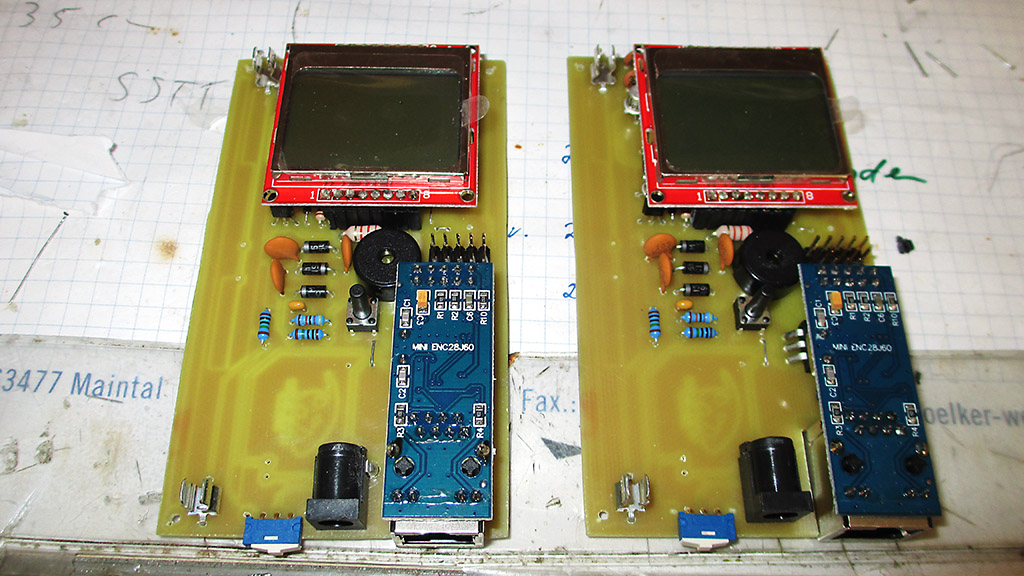
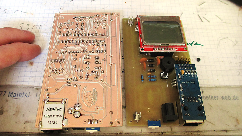
Horakus built two KIT1.1 units, using factory made PCBs:
Chris and Frederik redesigned the KIT1 using SMD components, and added a rechargeable battery! They also built a 3D printable case:
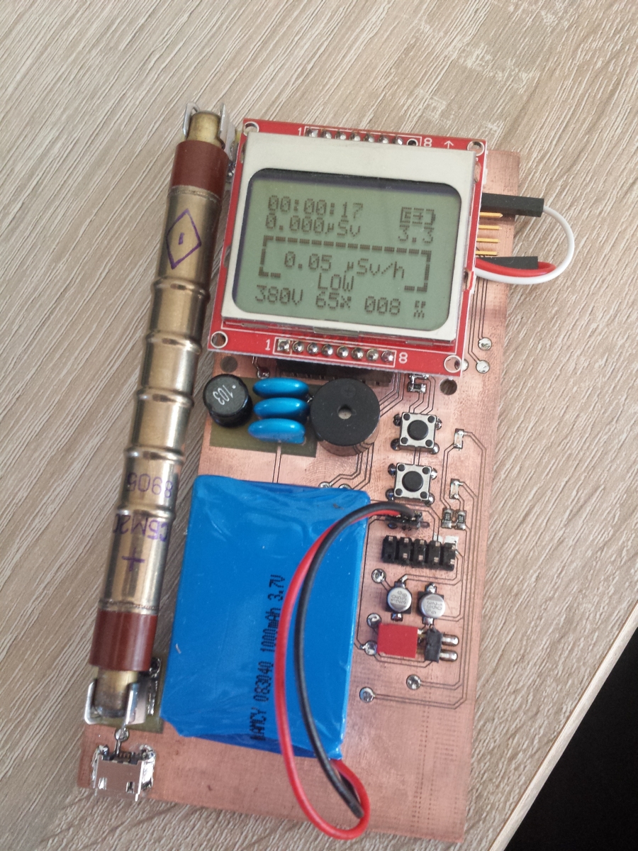
Eagle design files for Chris’s variant: SMD Geigercounter
Tino built two uRADMonitor KIT1.1 units, including his own PCBs. These devices were allocated IDs in the uRADMonitor network and will soon go online:
Pingback: DIY Dosimeter Geiger Counter Kit - PocketMagic
Pingback: uRADMonitor KIT1.1 - uRADMonitor
Salut Radu,
Se poate achizitiona acest kit? Am un contor realizat cu acelasi tub dar imi doresc si ceva sa stea in permanenta on-line.
salut Stefan. Nu am inca astfel de kit-uri pentru vanzare, dar sper sa am in curand. Eu le-am gandit ca open source ca sa si le construiasca cei interesati, dar nu e rau nici ce spui tu.
Salut, Radu.
Ajuta-ma, te rog, cu placa asta de retea pe care stiu ca ai folosit-o si la kitul de urad monitor pe care l-am luat de la tine in iarna. Am un montaj in care folosesc o placa de retea similara dar care este foarte instabila ( am incercat trei bucati deja). Am setat Arduino sa imi faca reset din ora in ora dar placa de retea tot apuca sa se blocheze in intervalul de o ora si pana la urmatorul reset nu ma pot folosi de datele respective. Tu cum ai rezolvat problema instabilitatii ?
Multumesc.
Salut Alex,
Raspund putin greu, sper ca nu prea tarziu pentru problema ta. Am observat si eu ca modulul uneori se blocheaza, dar mie imi rula pe intervale mai lungi, de zeci de ore.
Solutia a fost sa pun un watchdog, care reseteaza automat microcontroller-ul daca detectez probleme cu enc28j60 . Conditia e bazata pe raspunsul de la server: il primesc sau nu. Daca timp de 5 minute nu primesc un raspuns corect (HTTP 200), watchdogul va initia resetul.
Cam la fel ar trebui sa faci si tu: zici ca ai reset-ul implementat, iti ramane doar sa verifici succesul operatiilor de retea care le faci.
Very cool project, recently I was looking for a simple and cheap Geiger counter project, and this seems great for DIY.
I really wish it had GPS and MicroSD for data logging, though. Have you ever thought of adding that to your project?
Ublox NEO-6M is a cheap (~10USD) GPS module that can easily be used with Arduino. Add a Micro SD board (~1USD) and a RTC board such as DS3231 (~1USD) and I think the project becomes way cooler and great for portable use.
When you’re back at home the data could easily be uploaded back to the computer and displayed on a map.
What are your opinions on that? 🙂
Hello JAcob, thanks for the feedback, my opinion on this is that yes, we’ll see the changes implemented soon.
Very nice Radu 🙂 In the meantime I will try to build the current version. Hopefully I will be able to easily source all of the parts. Thanks for your amazing work, keep it up 🙂
Perfect. When ready let me know so I can assign you an ID for the uRADMonitor network.
Hello Radu Motisan please reset fee for the device if you can
Hi Andrey, what can I do for you?
Radu, vreau si eu un pcb daca mai ai disponibil, vreau sa l folosesc pe post de detector mobil alaturi de cel stationar.. 🙂
Hey,
would a BYV26C work as a substitute to BYV26E?
Thanks.
Yes!
Alex, o sa-ti trimit unul.
Hi Radu,
I shall make a budget and buy one of these kits. 🙂
You seem to be building based on ideas I sent to V.S. and that is okay by me since I play and dream but never build the devices myself.
Be invited to get in touch and I shall send you some more ideas.
Peace !
Peter
Salut Radu!
Au aparut cumva kiturile pentru v1.1?
O zi faina, Calin.
deocamdata doar pe indiegogo, dar o sa fac un shop online in lunile urmatoare.
Ok. Deci il gasesc pe Indiegogo.
Il iau de acolo, nu-i problema.
Multumesc de raspuns.
O seara faina.
Calin.
I am very interested in building the Geiger counter kit V 1.1 . I do not see a link on your website to a kit of available parts. including the PC board, pre-programmed microcontroller and price. I have built the kit available from Electronic Goldmine using their C6986 counter kit with their G18160 Geiger tube and am quite disappointed with the sensitivity. That’s why I am interested in your kit. I have a second question. How are you measuring the applied voltage to the Geiger tube without loading down the circuit??? I have both a Fluke 77 11meg ohm multimeter and a Simpson 260 analog with a impedance of 20K ohm per volt and still can not get a decent reading. Thank you for your reply.
Bill
Salut
Ai cumva de vanzare cablaje pentru kitul v1.1?
Multumesc!
@William, the impedance of the circuit measuring the voltage, part of the regulator block has a 10M impedance. You can (still) get the KIT on indieGogo: https://www.indiegogo.com/projects/uradmonitor/x/7951265#/ . The sensitivity of this model is excellent.
@Florin: deocamdata nu, dar am sa incerc sa ofer si asa ceva in curand. De cate ai fi avut nevoie?
Salut
Apai de vreo doua cablaje, dar nu-i mare graba…. Eventual, poate le comand de pe OshPark…
Multam frumos.
Vad ca esti din TM . Cu doua cablaje te ajut fara probleme. Lasa-mi un numar de telefon pe mail.
Salut, Radu.
Am un coleg care ajunge sapt viitoare in TM ( marti, miercuri .. ), poate reusiti sa va sincronizati pt cablajul ala 🙂
Thnx.
Bine. Da-i nr meu.
Sa mi-l lasi pe mail pentru ca nu dau de el. Thnx 🙂
Hi, Radu!
Please tell us if the speaker is “self-oscillating” as it says in the schematic (meaning it has an internal oscillator and needs only DC power), or is a regular speaker that needs to be driven with an oscillating signal from the Atmega.
Thanks!
3V, self oscillating. Not a regular speaker. No driver required.
Could you please state the exact model that you are using? On the latest schematic all I could find is “speaker/AL60P”, but I’m not sure that AL60P is self-oscillating. Thanks!
Razvan, I’ve used a 5V speaker and it works fine.
This is what I used: http://www.ebay.com/itm/201502525621
Thank you, Jacob! It’s great to see other builders giving a helpful hand!
I’ll order this:
http://www.tme.eu/gb/details/ld-bzeg-1203/electromagnetic-sounders-with-generator/loudity/
as part of a larger order.
Pingback: Model KIT1 - Production Ready! - uRADMonitor
Salut. As construi si eu un astfel de dozimetru, dar nu am vreme sa stau sa fac cablajul. Unde as putea vb ca sa imi faca un cablaj???
Sunt din Baia Marea
ma uit sa vad daca mi-au mai ramas si daca am iti pun unul pe posta. trimite-mi un email cu adresa (ai mailul meu la sectiunea About)
I’ve seen on the pictures that accompany the project details that monolithic capacitors are preferred. What is the reason? I have some good ceramic disk 33 pF capacitors.
Hello, Radu!
My project, although is based on your latest design (HV without transformer), will use an LED as well as the active speaker. I have seen that your older designs used a separate pin for driving the LED. Do you think it will be OK if I hook up the LED on the same pin with the speaker? I mean before the transistor that drives the speaker. With its own resistor, of course. Please see my earlier question regarding the ceramic disk 33 pF caps, are there any specific reason to choose monolithics? I already have the ceramics and really no other reason to order any more parts…
The ceramics are ok! Use those is that is what you have. You can connect the LED with the speaker.
Buna Radu,
Sunt interesat de un uRADMonitor model D.
Pentru asta doresc un barter, un kit model D contra manopera.
Daca este convenabil, sunt interesat sa asamblez din kit-urile pe care le ai la vanzare pentru toate componentele unui kit model D.
Daca este ok astept un raspuns pe mail despre conditiile de colaborare.
Cu salutari,
Dan
Mersi de interes Dan. Ti-am trimis mailul.
I want to make my own PCB like Tino , can I just take the 1.1.103 version and just etch the bottom layer and connect the grounds together?
I’m a student and don’t have the money to buy a kit but I like your project a lot and I would also like to build a city polution sensor because in the winter we have big problems because of coal and old diesel cars.
Hi Adrian, absolutely, you can do it single layer and simply use bridges to connect the top. LEt me know if there is anything else I can help you with.
I built a kit 1.1.103 but I have a problem, with 3.4v tube gets only about 290-300v, only after raising the power voltage to 5V everything works … any ideas?
Careful about using 5V as it will burn your 5110 and the enc28j60, unless you only use it for the coil.
The circuit is able to boost from 3V, if this doesn’t work for you , check the following:
– the MPSA42 transistor : use another one from a different source / manufacturer , this is a highly critical component.
– the 2.2mH coil, use a different one, try one with a lower resistance, or if not available , use a 1mH coil.
unfortunately still not figured what is wrong, MPSA from 3 manufacturer with slightly different results, but everything about 300v, my coil 2.2mH is approximately 24 ohms, using 1mH coil voltage drops to 120 V ….
Hi Maciej, I had similar results. I have resolved it by changing the mpsa42 to bf299. Also your inductor show have a lower resistance. These are my parts for your reference: http://www.reichelt.de/Fixed-Inductors-axial/L-XHBCC-2-2M/3/index.html?ACTION=3&GROUPID=3179&ARTICLE=138556&OFFSET=16& and http://www.reichelt.de/Transistors-BF/BF-299/3/index.html?ACTION=3&GROUPID=2883&ARTICLE=5464&OFFSET=16&
Hello Sven, can you post a few pics with your variant? Links for that: http://www.uradmonitor.com/topic/soldering-the-kit1/ and https://github.com/radhoo/uradmonitor_kit1
Hello Maciej, any progress?