
For many of my previous projects I used AVR Microcontrollers extensively. I started with the Atmega8 and moved to superior AVR variants depending on the application complexity and requirements. Before designing any particular application, I usually do my research on a development board. It is a PCB featuring the target microcontroller and minimal support logic that usually covers a regulated power supply, pin headers to connect peripherals and/or a few LEDs used for basic debugging.
Such boards are available in many shapes and colours, from simple to complex and most of the times they are affordable (after all we’re talking about a minimal PCB with a microcontroller and a few, mostly passive, components).

For some various reasons I had to design my own core development board featuring an Atmega128A-AU microcontroller from Atmel. This is an excellent piece of silicon, featuring 128KB of flash memory, a max operating frequency of 16Mhz and a generous total count of 64 pins offering plenty of I/O options.
When doing prototype PCBs I usually go for a toner transfer manufacturing process, that might have its issues but can prove reliable once you get it right.
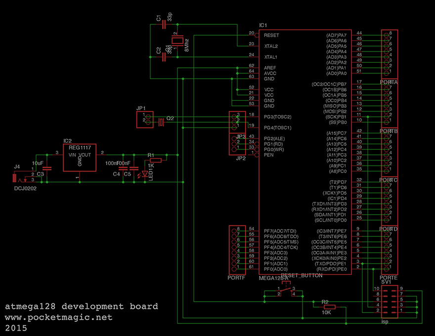
Development board schematics and PCB
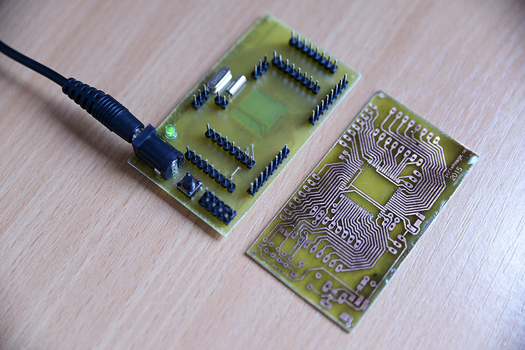
This was rather simple to do: designing a board that connects most of microcontroller’s I/O ports to pin headers, and for the rest traces to a main 8Mhz quartz crystal, a voltage regulator (AMS1117), a DC Jack, a reset button and a LED to show when power is connected. There is a second 32.768KHz crystal that I plan to use with the Atmega128’s internal real time clock circuit.
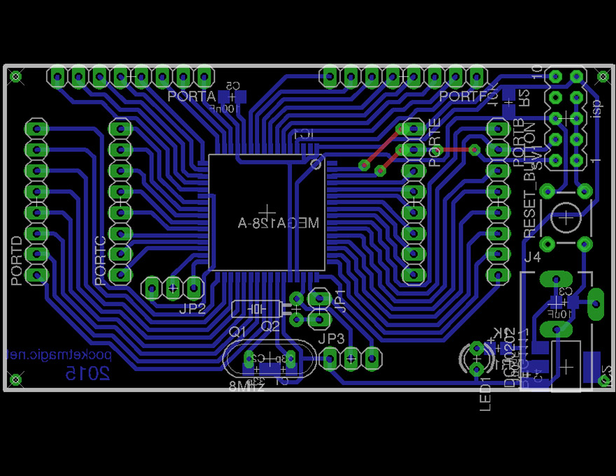
You can download the Eagle files, under license GPL v2.0, here: atmega128_dev_board.
Toner transfer tips
There are many tutorials on how to create PCBs using toner transfer, so I will not waste time with redundant information. Instead here are some tips that for me at least, made the process easier.
-1-Clean the copper!
Before transferring the toner, do a zealous job at cleaning the copper surface. Use abrasive paper, abrasive brush or any other mechanical means of cleaning the surface, but try not to scratch it. So if using emery paper, make sure the granularity is soft. Deep scratches can prevent toner form reaching the copper surface and forming a good bond, resulting in interruptions in your traces. Avoid that at all cost.
-2-Use acetone!
Once you get a nice shiny surface, clean it with acetone. I used to skip this step, and later I realised that grease will prevent toner from sticking to the copper. So acetone is a must.
-3-Avoid deformed borders!
Finally, use a PCB that is bigger than actually needed. If your copper board is exactly the same of your diagram, the border will likely show deformations resulting from the cutting process. If the board is not perfectly flat, in some areas you won’t get a good contact between the paper carrying the toner and the surface, and the transfer will give poor results. So just leave a few extra unused space, and transfer your diagram in the centre of your board.
-4-Use transfer paper
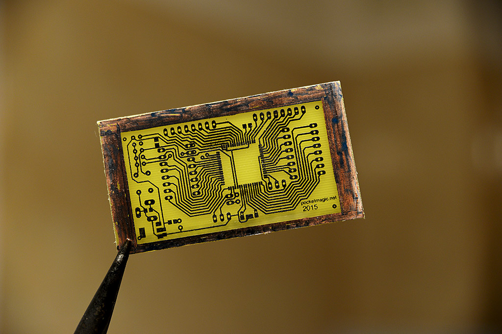
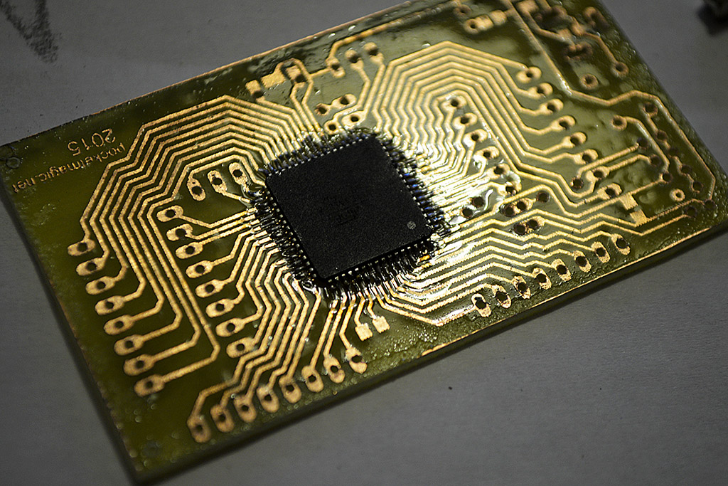
Use the glossy (mostly yellowish) transfer paper. Its glossy side doesn’t have exposed micro-fibers like in the case of normal paper. Hot/melted toner will not get soaked, but instead it will transfer to the copper side (assuming it was nicely cleaned before).
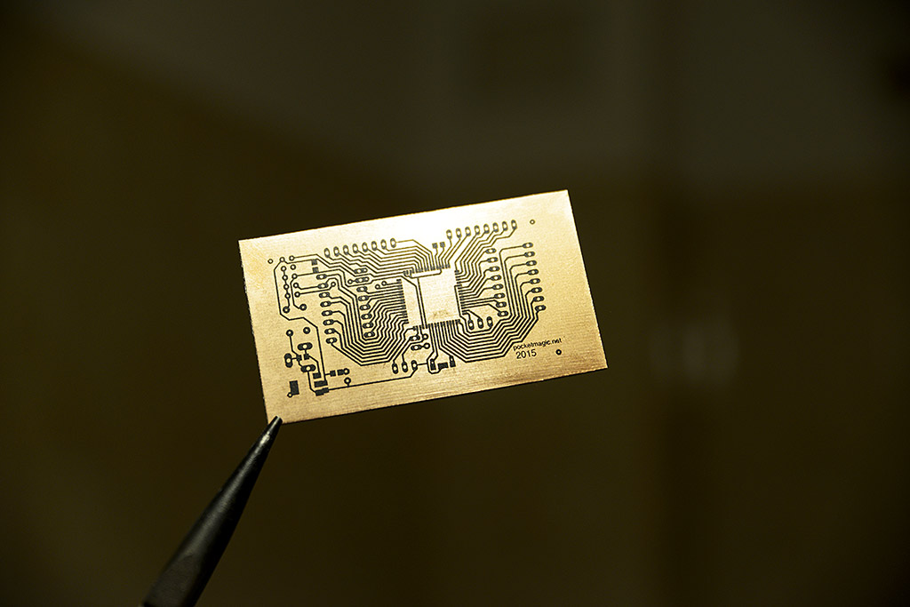
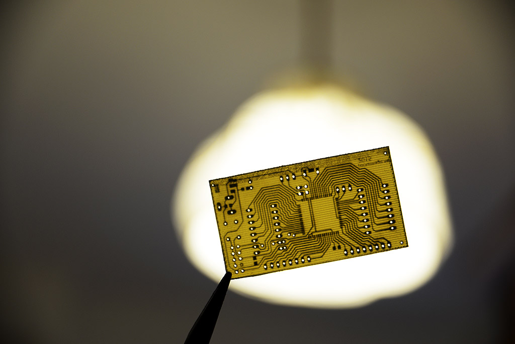
If all goes well, you should get a nice result:
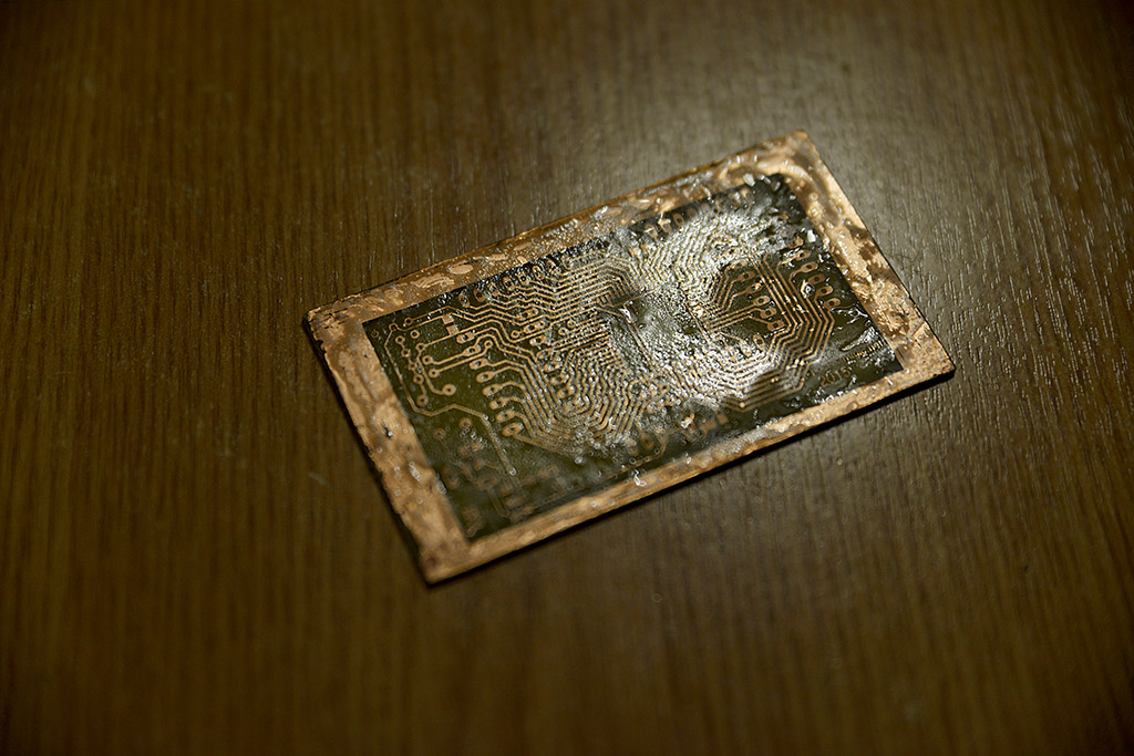
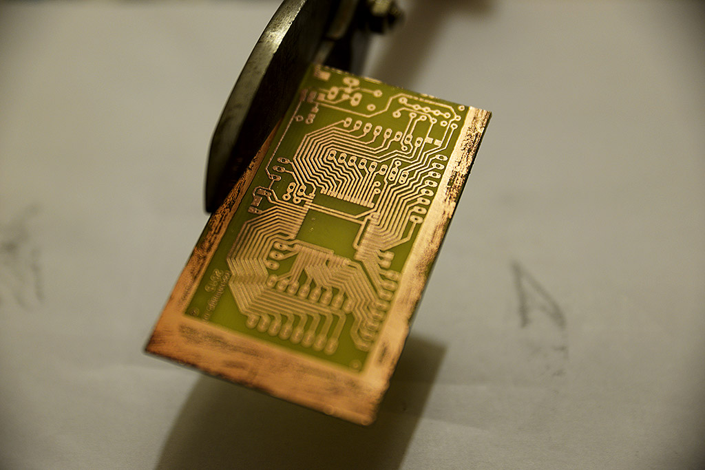
-5-Keep an eye on the watch when corroding
Printer toner transferred using heat will form a molten layer that hardens almost immediately as the temperature decreases. This normally offers a good protection against corrosion agents, like Ferric Chloride, however micro-cracks can form in this layer, allowing some of the corrosive substance to reach the copper – check the status from time to time, and don’t let your PCB have a bath for more than required.
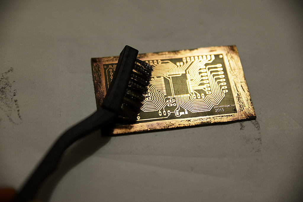
-6-Clean the toner with a soft metallic brush
Really, this is much easier than using solvents which tent to dissolve the black pigment and smudge the entire PCB. Gently press the brush not to ruin your thin traces (it can happen), and you’ll get the job done easy.
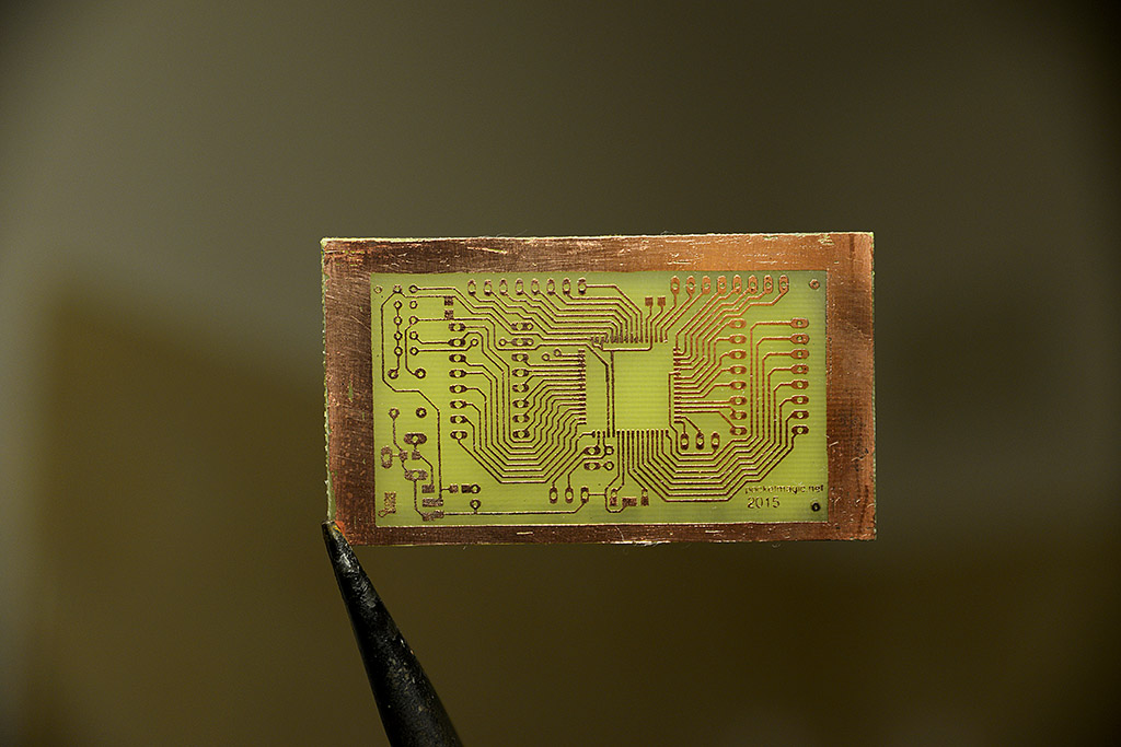
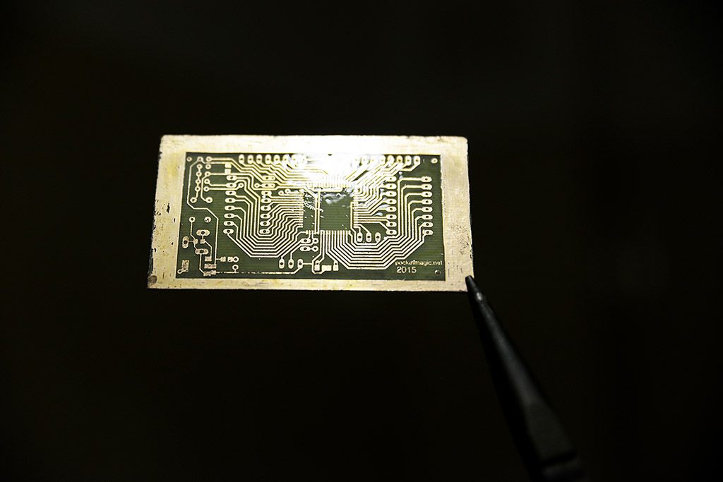
-7-Protect the copper
The thin traces of exposed copper can, in time, oxidise to the extent where they loose conductivity. To prevent this from happening, a protective coating is a must. What I do is to create a concentrate solution of rosin dissolved in acetone. It’s a very sticky product, so try not to pour it on your fingers. Put some of this on your board and spread it evenly. You’ll get a very unaesthetic result. The trick is to heat the board to the point where the entire acetone evaporates, and the remaining resin melts and forms a transparent, glossy layer. This is both a good protector for copper, but it also facilitates upcoming soldering (better than flux I’d say).
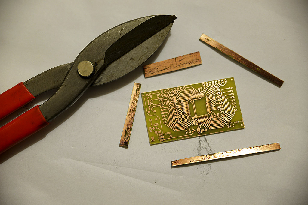
-8-Cut the extra PCB border
Tip 3 asked you to leave some extra space on your PCB, now’s the time to remove it. Use sheet metal shears for that, they work great.
The result
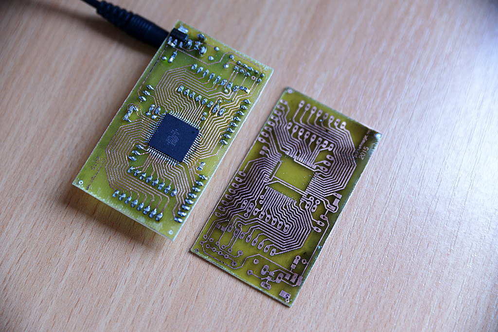
I usually make at least two boards where I only needed one, to be covered in case something goes wrong. With the toner transfer method you never know.
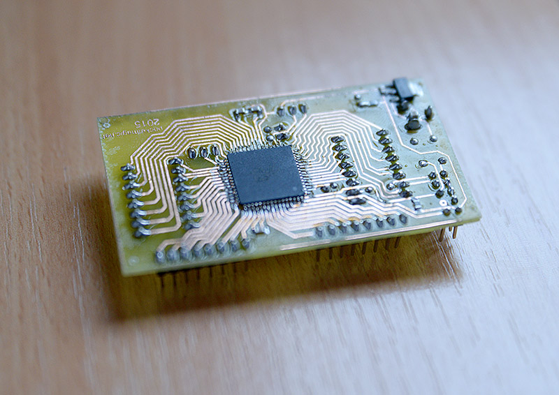
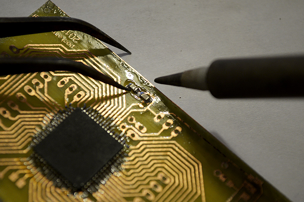
After drilling the holes for the header pins and soldering the few SMD components (the atmega128 was fun to solder), the board is ready. Hooking it to the computer via an usbAsp programmer shows it works properly, and I was able to load the first test program and set the fuse bits. More pics for you to see the result:


Pingback: Atmega128 Voodoo - PocketMagic
Pingback: ILI9163 LCD Library - PocketMagic
Pingback: ILI9341 touchscreen LCD Library - PocketMagic