Apparently I had no better inspiration on how to name this post. It all started with a nice sunny day, when I was in great shape for doing creative work. My plan was to do some research on the following uRADMonitor models B/C, to put everything together and start the design of the new device. With all the extra new features, it was clear I needed a microcontroller upgrade, from the current Atmega328p to the more generous Atmega128.


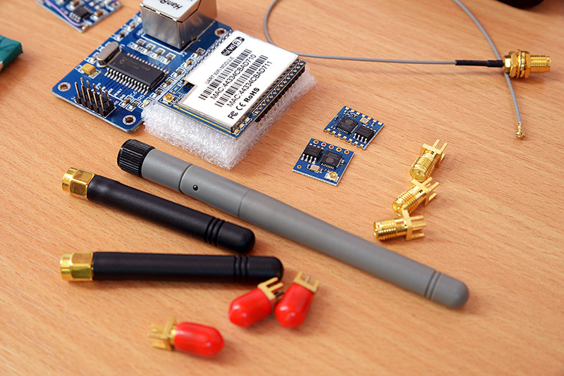
I had an Atmega128 development board already, so I was able to start right away. First things to do, were to adapt the existing code for the new registers: add real time clock support (thanks for TOSC1/TOSC2 with 32.768kHz crystal), one interrupt for pulse counts, one timer to generate the PWM – coupled with an ADC port for voltage measurements to regulate the output and so on.
I started with the timer0, and configured it for asynchronous operation:
...
// By setting the AS0 bit in ASSR, Timer/Counter0 is asynchronously clocked from the TOSC1 pin.
// When AS0 is set, pins TOSC1 and TOSC2 are disconnected from Port C.
ASSR |= _BV(AS0);
// prescaler set to 128, that gives us 32768/128=256 Hz
TCCR0 |= _BV(CS02) | _BV(1<
And the ISR code would just blink a led, since my test board already had two built in useful for such debugging purposes.
ISR(TIMER0_OVF_vect)
{
// do something every second, eg. blink a led
}
Quickly compiled the code pushed the hex to the microcontroller and, AND, and.... NOTHING! The bloody led would not blink.
Ok, I must have done something wrong I figured, went back to synchronous mode, checked again: Nothing.
Going over the datasheet, code looks OK (hey there are only a few lines of code, what could go wrong). No result.
Back to searching on google, got a few examples, those didn't help either. My timer will not function - period.
Finally I reached Atmel over Twitter, and they were very helpful: despite writing them over the weekend, I got the code snippet for the Atmel 1259 Real Time Clock AVR134 article in just a few moments (Thanks guys!! You rock!). I was unable to try it right on spot, as the night hours were advancing.
Next day, I decided to give it another try. But instead of focusing on the various registers and the more complicated hardware details, my plan was simple: to write a class to handle a Digital pin, that will be used for LEDs or any other output actions. So I put the timer0 on a short pause.
To go with the leds, a messy code that looks like this:
int dq = PA1;
DDRA |= (1 << dq); // prepare pin for output
if ((PORTA & (1 << dq)) > 0) {
PORTA &= ~(1 << dq); // pin low
} else {
PORTA |= (1 << dq); // pin high
}
would instead be translated to a nice, general purpose class:
class DigitalOut {
volatile uint8_t *m_pport;
uint8_t m_ledstate, m_dq;
volatile uint8_t* Port2DDR(volatile uint8_t *port) {
return port - 1;
}
public:
// Create a DigitalOut connected to the specified pin
DigitalOut(volatile uint8_t *port, uint8_t dq) {
// save globals
m_pport = port;
m_dq = dq;
// set for output
*Port2DDR(m_pport) |= (1<
Using this class, controlling LEDs would get really simple. A simple code to blink two LEDs in anti-phase would look like this:
DigitalOut LED1(&PORTG, PG1), LED2(&PORTG, PG2);
int main(void) {
int st = 0;
while (1) {
LED1 = st; //flip
LED2 = 1 - st; //flap
_delay_ms(1000);
// toggle state
st = 1 - st;
}
}
Beautiful. Just that it doesn't work. Using the simple toggleLed instead works. Why? No clue. I've used classes similar to this DigitalOut in the past and had no issues. But now, everything seems to go wrong. Combined with the timer0 problems, the entire programming sessions seems closer to magic than science (Voodoo!!)
The scientific approach
Well now, the scientific approach is to use logic to bring light to every corner, and thoughtfully verify all assumptions. I did many additional tests, and got a very inconsistent behaviour. Then I decided to go redundant, and made a DIY development board to try my code on.
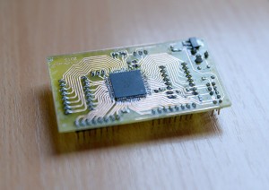
The results were similar. I decided to take a break.
Two days later, while going through the same facts over and over again, I decided to try powering the board using 5V. Note that both boards I've used had the Atmega128A, with the power interval of 2.7-5.5V. I wrote the hex again, but this time the DigitalOut class worked! I took the second board: it worked as well! The code wasn't changed. The only change was powering the unit using 5V and re-downloading the hex. But then I changed the supply to 3.3V and the boards were still working: with the DigitalOut class code loaded, the blinks would flicker nicely, one at a time, at a 1Hz frequency.
My wife, who is also a software developer and has to bear my voodoo stories every time something doesn't work for me, heard me say I used two separate programmers when writing the code. They were both usbAsp programmers, but one was set for 3.3V and the other for 5V. She suggested that the problem might be caused by downloading the HEX code at a lower voltage (that is with the 3.3V programmer). In my setup these were also used to power the boards via their regulated Vccs.
This made little sense, as the programmer shows a confirmation screen, and does flash code verifications, and those were ok for both the 3.3V and the 5V programmers. Yet... writing the code using the 5V programmer gives me the expected result, when using the 3.3V programmer creates all the issues I had to go through, presented above. I tried this several times to confirm, and it was so on both boards. There was nothing wrong with the code, the board, but the programmer voltage. Once the 5V usbAsp was used to download the hex, I can power the board at 3.3V and will function just fine!
So at least there is a consistent explanation and the problem in my case was somehow generated by the cheap usbAsp programmer I've used. Hope this story will help someone else save precious time. Using the 5V usbAsp, the timer0 code works perfectly as well.
Update - the root cause - 15 July, 2015
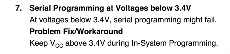
The truth is I was never really satisfied with the 5V solution. There is an entry in the Atmega128 Errata presenting an issue with programming voltages below 3.4V (and I used 3.3V initially), but in my case, avrdude verified the code successfully. Also a simple led blinker code worked, while a more complex class DigitalOut code didn't.
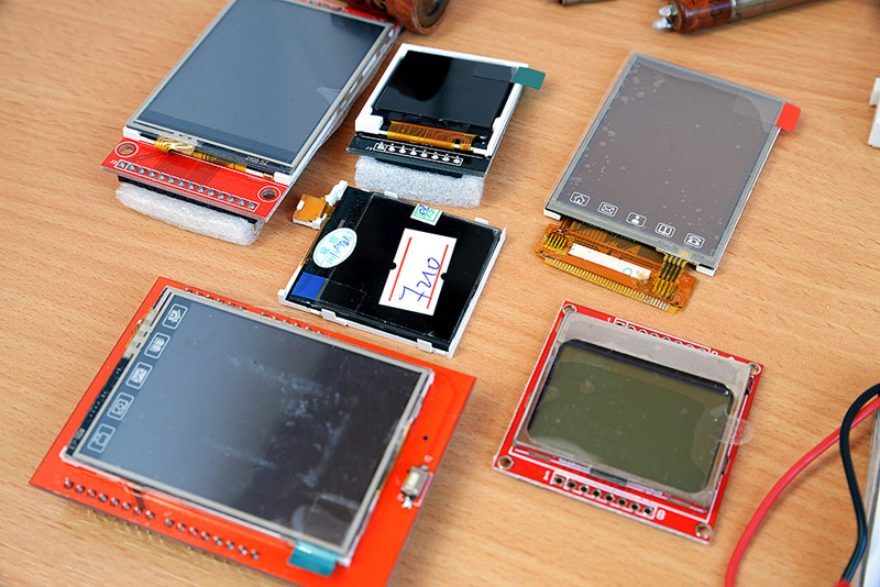
While working on my Hackaday 2015 Prize project, the two development boards I was using, both based on atmega128 started to behave erratically. The issue made me blame parts of code related to the esp8266 or the ILI9341 modules, and I wasted a lot of time. Finally I stripped the code down to a blinking LED, just to see that the original Voodoo issue is back. No 5V programmer would make it go away this time.
"Any improbable event which would create maximum confusion if it did occur, will occur."
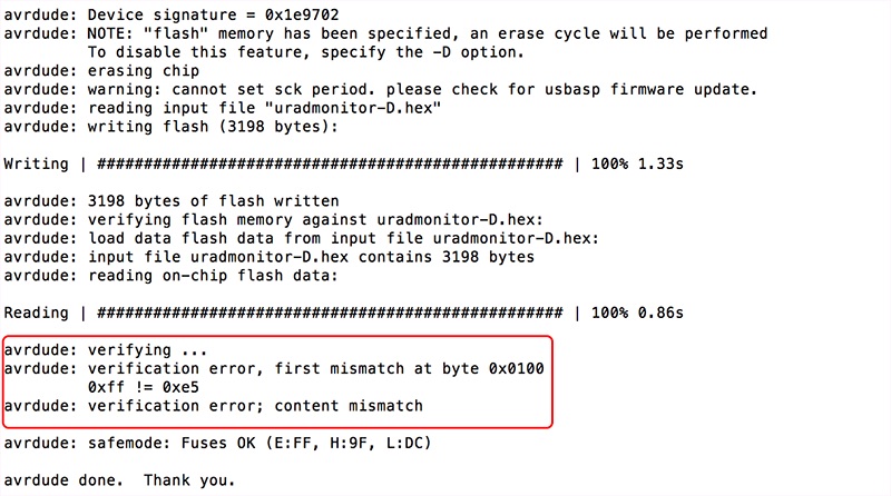
This almost made me switch to STM32F4 microcontrollers as an alternative, but the time was too short for that, as the volume of code needed to be ported was too high. So back to AVRs, I purchased a few alternatives like the mega64, various programmers (initially I used usbAsp with avrdude under MacOS) hoping to find a working solution. Which I did not. This didn't stop me from rechecking everything over and over again. Between several inconsistent software runs, I noticed a code verification error, "first mistmatch at byte 0x0100" and "verification error; content mismatch":
Tracking the issue I ended up on the avrdude website and their bug tracking system, where bug #41561 presented just that, but for the atmega64. Apparently a change in avrdude 5.11 introduced memory tagging, as explained by Joerg Wunsch :
Before, all memories had been treated as a large block of bytes (N = size of that memory area on the chose device), regardless of whether their contents actually came from an input file. Now, only those regions are touched that have corresponding bytes in the input file. (For paged memory areas, the term "region" here refers to the situation where at least one byte within a memory page has been mentioned in the input file.)
I traced the ISP traffic with a logic analyzer, and decoded the data stream back into ISP commands. See the attachment for the full trace. The bug is that the "write memory page" command is issued twice:
Time 393.416 ms: MOSI Load program memory page, address 0x007f, low byte, value 0x6d
Time 393.910 ms: MOSI Load program memory page, address 0x007f, high byte, value 0x6d
Time 394.370 ms: MOSI Write program memory page, address 0x007f
Time 394.804 ms: MOSI Read program memory, address 0x007f, high byte, value 0xff
Time 395.218 ms: MOSI Read program memory, address 0x007f, high byte, value 0xff
Time 395.688 ms: MOSI Read program memory, address 0x007f, high byte, value 0xff
Time 396.131 ms: MOSI Read program memory, address 0x007f, high byte, value 0xff
Time 396.538 ms: MOSI Read program memory, address 0x007f, high byte, value 0xff
Time 397.013 ms: MOSI Read program memory, address 0x007f, high byte, value 0xff
Time 397.427 ms: MOSI Read program memory, address 0x007f, high byte, value 0xff
Time 397.903 ms: MOSI Read program memory, address 0x007f, high byte, value 0xff
Time 398.368 ms: MOSI Read program memory, address 0x007f, high byte, value 0xff
Time 398.805 ms: MOSI Read program memory, address 0x007f, high byte, value 0x6d
Time 399.222 ms: MOSI Write program memory page, address 0x007f
Time 399.686 ms: MOSI Read program memory, address 0x007f, high byte, value 0x6d
Time 401.510 ms: MOSI Load program memory page, address 0x0080, low byte, value 0x6f
Time 402.139 ms: MOSI Load program memory page, address 0x0080, high byte, value 0x72
After filling the page buffer, the page is being programmed at time 394.370 ms. Then, USBasp polls the page for a response != 0xff, which indicates the end of the write operation (time 398.805 ms). However, just after this, it issues another "write page" command at 399.222 ms, but then proceeds to fill the page buffer again for the next page.
Apparently, the old devices (ATmega64/128) respond to the second page write immediately with a poll value of "OK" (i.e., they return the correct value), yet they are still busy programming afterwards. In contrast, the newer devices (like ATmega1281) correctly respond again with 0xff for the second page write operation:
Time 391.417 ms: MOSI Load program memory page, address 0x007f, low byte, value 0x6d
Time 391.910 ms: MOSI Load program memory page, address 0x007f, high byte, value 0x6d
Time 392.371 ms: MOSI Write program memory page, address 0x007f
Time 392.806 ms: MOSI Read program memory, address 0x007f, high byte, value 0xff
Time 393.218 ms: MOSI Read program memory, address 0x007f, high byte, value 0xff
Time 393.689 ms: MOSI Read program memory, address 0x007f, high byte, value 0xff
Time 394.130 ms: MOSI Read program memory, address 0x007f, high byte, value 0xff
Time 394.539 ms: MOSI Read program memory, address 0x007f, high byte, value 0xff
Time 395.014 ms: MOSI Read program memory, address 0x007f, high byte, value 0xff
Time 395.428 ms: MOSI Read program memory, address 0x007f, high byte, value 0xff
Time 395.903 ms: MOSI Read program memory, address 0x007f, high byte, value 0xff
Time 396.369 ms: MOSI Read program memory, address 0x007f, high byte, value 0xff
Time 396.806 ms: MOSI Read program memory, address 0x007f, high byte, value 0x6d
Time 397.222 ms: MOSI Write program memory page, address 0x007f
Time 397.687 ms: MOSI Read program memory, address 0x007f, high byte, value 0xff
Time 398.130 ms: MOSI Read program memory, address 0x007f, high byte, value 0xff
Time 398.539 ms: MOSI Read program memory, address 0x007f, high byte, value 0xff
Time 399.013 ms: MOSI Read program memory, address 0x007f, high byte, value 0xff
Time 399.431 ms: MOSI Read program memory, address 0x007f, high byte, value 0xff
Time 399.903 ms: MOSI Read program memory, address 0x007f, high byte, value 0xff
Time 400.368 ms: MOSI Read program memory, address 0x007f, high byte, value 0xff
Time 400.805 ms: MOSI Read program memory, address 0x007f, high byte, value 0xff
Time 401.218 ms: MOSI Read program memory, address 0x007f, high byte, value 0xff
Time 401.688 ms: MOSI Read program memory, address 0x007f, high byte, value 0x6d
Time 403.640 ms: MOSI Load program memory page, address 0x0080, low byte, value 0x6f
Time 404.155 ms: MOSI Load program memory page, address 0x0080, high byte, value 0x72
which explains why they can be programmed fine. But obviously, the second page write operation is completely unnecessary.
The difference ... is that AVRDUDE now works on a per-page basis throughout all programmers, rather than on the entire device memory. If I remove the USBASP_BLOCKFLAG_LAST (line 1330, function usbasp_spi_paged_write()), it seems to work as intended
And indeed it works! Personally I opted for using a version prior to 5.11 (CrossPack-AVR-20100115.dmg), as that was readily available for MacOS, but as soon as I finish my work for the HackADay Prize 2015, I'll have the time to properly compile the latest code that fixes the issue.
For now it properly writes my precious hex files correctly and I can continue the development. The kind of corruption it previously caused was so diverse in side effects, that tracking it to a root cause was very complicated, as presented in this article. Now that the problem is gone I can only conclude it's another lesson learned, among the many of the kind in software development.


Meda Motisan liked this on Facebook.
Deaconu Andrei liked this on Facebook.
Evan Stoddard liked this on Facebook.
Gursimran Singh Gahir liked this on Facebook.
Scott Bogard liked this on Facebook.
Ovidiu Motisan liked this on Facebook.
Rodica Motisan liked this on Facebook.