
A complicated project
July was a tough month, and August is no different. Due to some components arriving late, I’ve only been able to start my work on the Hackaday.io project with considerable delay. So I had to catch up with everything and squeeze the entire development work for this complex project in a month’s timeframe.
But the plan was solid and seemed doable … unless Murphy’s laws of chaos wouldn’t start to kick in, adding more trouble to the already busy schedule.
First, it was the atmega128 voodoo issue I wrote about a while ago. For a few days I’ve been unable to use my two atmega128 development boards and all development efforts stalled, in a parallel useless new quest for understanding why a basic led toggle code would behave erratically. Apparently the problem was related to avrdude, and at least this brought a logical clear explanation to what was going on. But this got me into ARM STM32 microcontrollers as well, so at least I learned a few new things.
Then one of the three Mics-vz-89 decided to stop working and take the entire I2C bus down, so nothing worked until I removed the faulty sensor. I later learned about this issue from SGX support, but it was another day lost with apparently another voodoo-like issue. The replacement is still in transit, hopefully I’ll get it soon.
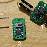
The story goes on. I had some issues with the ILI9341 displays, which resulted in a few getting damaged. I was left with a single one, and no quick way to order two more – which I needed for the 3 prototypes for the #bestproduct competition. Luckily a previous order arrived in time, with 4 brand new ILI9341 LCDs. But no touchscreens. I had two scavenged from the broken modules, but the touch controller was destroyed (xpt2046). So no way to get three working displays with touchscreens.
The solution to all
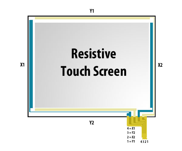
For a few minutes I was clueless. I even considered changing the way my project worked, using some bluetooth modules to display data on a smartphone. Obviously that was a bad idea. My toolbox had a different LCD waiting for some good use. It had a touchscreen, that was a little different because of some buttons printed at the bottom. But the size, connector and apparently type matched. But no XPT2046 driver. Well… who needs that anyway? The XPT2046 serial communication would have used 5 precious pins, while I can access the resistive touchscreen directly via ADC, and use only 4 pins! It’s obviously an excellent solution. From the 4 pins, namely the X+, Y-, X-, Y+, only 2 need to be ADC. For the algorithm I’ve used, those are X- and Y+. The other two can be connected to any GPIO.
Some technical details
Resistive touchscreens rely on two electrically separated layers to compute coordinates. When we touch the screen, the two layers get into contact at the specific location we touch. As the layers are built like resistors, the point of connection results in particular resistance values that can be determined across the terminals. The resistance values are linear across the X and Y directions. Meaning that the resistance we read can be linearly associated to coordinates on screen, either on the X axis or on the Y, finally allowing us to compute the point where the screen was touched.

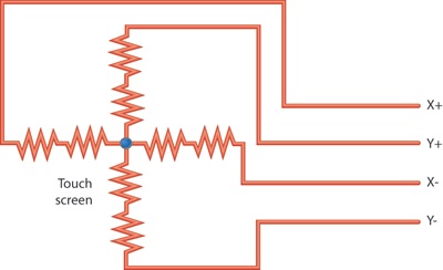
(image source here)
Since the touchscreen is mounted on top of the display, it is usually good practice to calibrate it’s output to match the resolution of the LCD. As an example, my ILI9341 are used in portrait mode and have a resolution of 240×320 pixels. Therefore I made my touchscreen code to return coordinates to match this surface.
The code and the algorythm
For the Hackaday.io project, I had to write a lot of code to handle the hardware layers and make the application development easier. Take for instance the ADC class or the general purpose DigitalPin handling all GPIO. The touchscreen code becomes nice and clear:
/*
	 * TouchScreen constructor
	 * init the GPIO pins and set the orientation (default portrait)
	 * XN and YP are ADC pins, YP and YN are general IO
	 */
	TouchScreen(ADC10b *adc, DigitalPin *xp, DigitalPin *yn, DigitalPin *xn, DigitalPin *yp, Orientation orientation = PORTRAIT, uint16_t r = 0);
...
uint16_t TouchScreen::readRawX(void) {
	xn_adc->config(DigitalPin::INPUT);
	*xn_adc = 0;

	xp_io->config(DigitalPin::INPUT);
	*xp_io = 0;

	yn_io->config(DigitalPin::OUTPUT);
	*yn_io = 0;

	yp_adc->config(DigitalPin::OUTPUT);
	*yp_adc = 1;

	return 1024 - m_adc->read(xn_adc->getPin()) - 1;
}


uint16_t TouchScreen::readRawY(void) {
	yn_io->config(DigitalPin::INPUT);
	*yn_io = 0;

	yp_adc->config(DigitalPin::INPUT);
	*yp_adc = 0;

	xn_adc->config(DigitalPin::OUTPUT);
	*xn_adc = 0;

	xp_io->config(DigitalPin::OUTPUT);
	*xp_io = 1;

	return 1024 - m_adc->read(yp_adc->getPin()) - 1;
}

uint16_t TouchScreen::readRawPressure(void) {
	// Set X+ to ground
	xp_io->config(DigitalPin::OUTPUT);
	*xp_io = 0;

	// Set Y- to VCC
	yn_io->config(DigitalPin::OUTPUT);
	*yn_io = 1;

	// Hi-Z X- and Y+
	xn_adc->config(DigitalPin::INPUT);
	*xn_adc = 0;

	yp_adc->config(DigitalPin::INPUT);
	*yp_adc = 0;

	int z1 = m_adc->read(xn_adc->getPin());
	int z2 = m_adc->read(yp_adc->getPin());

	return 1024 - (z2-z1) -1;
}
And to scale the values to the LCD resolution , I went for the following:
bool TouchScreen::read(uint16_t *x, uint16_t *y, uint16_t *pressure) {
	uint32_t calX1 = 0, calY1 = 15, calX2 = 890, calY2 = 845;

	uint16_t rawp = readRawPressure();

	if (rawp == 0) return false;
	// two consequent reads to double check coords and reduce errors
	uint16_t rawx = readRawX();
	if (readRawX() != rawx) return false;

	uint16_t rawy = readRawY();
	if (readRawY() != rawy) return false;

	if (rawx < calX1 || rawx > calX2 || rawy < calY1 || rawy > calY2)
			return false;

	rawx = (rawx - calX1) * TOUCH_WIDTH / (calX2 - calX1);
	rawy = (rawy - calY1) * TOUCH_HEIGHT / (calY2 - calY1);

	if (m_orientation == PORTRAIT) {
		*x = rawy;
		*y = TOUCH_WIDTH - rawx;
	} else {
		*x = rawx;
		*y = rawy;
	}

	*pressure = rawp;

	return true;
}
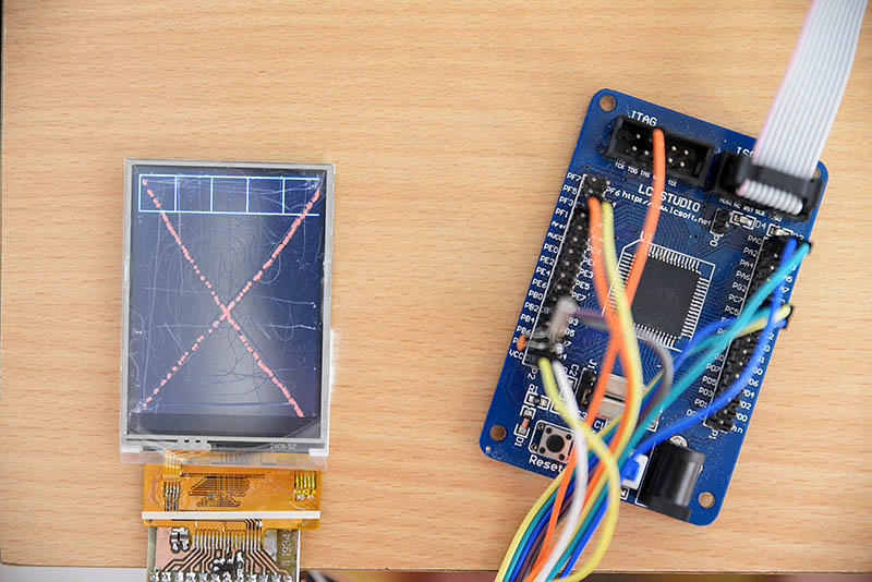
The cal** values must be determined for each touchscreen in part, as there’s an offset resulting from the way the touchscreen is mounted on top of the LCD, making the clicks a bit off from the LCD content. Also you’ll see that I read both x and y coordinates twice. The idea is to consider a coordinate as valid, only if two subsequent read operations result in the same numbers. This helps remove unwanted noise. As a comparison, here are two pics, in the first I took the (x,y) values as they were returned and drew them on the screen, while in the second picture I added this clever mechanism:
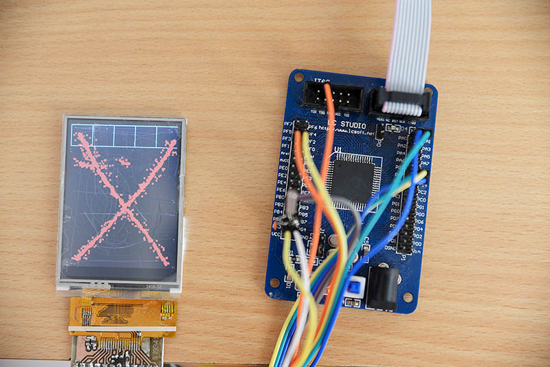

Now the buttons can be clicked accurately!
You can download the Resistive TouchScreen code as open source, under GPL v2, here or on Github.
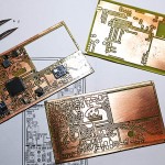
Pingback: A true hacker makes his own PCBs - PocketMagic
Pingback: Post Beta hardware iteration - PocketMagic
Dear Purchasing Manager,
Glad to know that you are looking for touch panel and we can help you do standard and customized design touch panel(4-wire resisitve, 5-wire resistive, G+G structure Projected capacitive)
We are touch panel factory in Shenzhen with more than 14 years experience in this field.(with 500+ workers and over 10,000 square meters production facility area)
Please send us your touch panel drawing for engineering evaluation. Looking forward to cooperating with you and you are welcome to visit our factory at your convenient time.
Best regards
Jack Qiu
Jack.qiu@btdisplay.com
Shenzhen BeiTai Display Technology Co., Ltd.
Factory Add: BeiTai Industrial Park,Tongfuyu Industrial Zone 15A,Kukeng Community,, Guanlan Street, Longhua District, Shenzhen 518110.
Tel: (86)755-8170 4080 Ext: 8502
Fax: (86)755-8170 4081
Website: http://www.btdisplay.com
点击此处,可以快捷回复给所有人…
Thanks Jack! I was indeed looking for some touch panels.