
Normally I wouldn’t a topic about such a simple device, but since there are many sites offering wrong information (for eg. this one short circuits your power source), I had to do it.
An H-bridge is an electronic circuit which enables a voltage to be applied across a load in either direction. If you need to learn more, read here.
Now, assuming you know what a hbridge is, let’s choose a topology for our implementation. You already know we’ll be needing transistors or mosfets (if not, please read the docs above), what you might not know is that these transistors will have to handle a high enough currents, especially when the motors they control are overloaded.
Some time ago, I’ve build a robot on a RC-truck, the load was so high because of the heavy batteries, that when the motors got the command to move forward they overheated and died.
So it’s important to use heat sinks, to dissipate the heat. So, for a h-bridge we will be needing 4 transistors, working in pairs at a time. If we use 2xPNPs and 2xNPNs we can have common collectors, and so, using a single heatsink per pair. For the topology this is the only requirement I will impose, and here is one possibility:

You will need to place the left side MJE2955 and MJE3055 on the same heatsink since they have common collectors. A separate heat sink for the right size transistors must be used.
These components support up to 10A current, so they will work well for small to medium motors.
Remember, a H-Bridge only controls 1 motor. So if you’ll need to driver the servo motor and also one main, propulsion motor you will need two separate h-bridges.
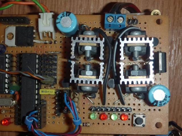
Here are some of the h-bridges I’ve created. On a board I usually create 2, since I mostly use 2 motored robots.

|

|
And here is a nice board having an ATMega8, a MAX232 for serial communication with a PC, and two h-bridges for controlling two big gear motors. Again I’ve used MJE2955/3055 pairs, but feel free to use any transistors/mosfets you have.

|

|
It runs well and it doesn’t heat up much. In case anyone needs further details on how this works, or other things like why we need the D1-D4 diodes, feel free to ask.
Also the R3,R4 resistors can be adjusted to suit your needs. For me, they are used to limit even further the current given by the microcontroller on the output control pins. Not really required in my case.
Some more pics:
 |
 |
 |
 |
EDIT: Here are some variants created by my readers
Victor, built a robot using a Mini ITX x86 board:
 |
 |
 |

Pingback: PocketMagic » Robo Evolution - how to build a better robot
Radu:
We came across your design and are very interested in giving it a try. Would you have any last minute recommendations before we purchase components? We are driving a small motor with (4)AA batteries but it is for a battle-bot so it is often stopped – the Arduino motor shield we have tried (burnt out) and the NYT circuit using a SN754410NE are both overheating. Also, is there kickback protection in your design?
Thanks Much.
Jules
Yes there is a good kickback voltage protection given by the four diodes.
Using some big transistors should give a very durable/robust design.
I’m using it to control some big geared motors and it works well. So go ahead, try this out!
Hey, I’d love to see your battle bot.
Radu:
We got all of the parts but are having a bit of a hard time going from schematic to wiring diagram to breadboard. Is there a chance you can send me a photo of the underside of image 2253 or another drawing that could help?
Thanks,
Jules
Pingback: PocketMagic » Perseus 3 Advanced Robot (using Windows Mobile)
Hi, if I only have TIP31, TIP42, 2N3904, and 2N3906 transistors, would it still be possible for me to accomplish this?
Hi Ethan, let’s see:
TIP31 is a 40V/3A NPN (http://www.datasheetcatalog.org/datasheet/MicroElectronics/mXuwuts.pdf)
TIP42 is a -40V/-6A PNP (http://www.datasheetcatalog.org/datasheet/fairchild/TIP42.pdf)
2N3094 is a 40V/0.2A NPN (http://www.datasheetcatalog.org/datasheet/fairchild/2N3904.pdf)
The TIP31 and TIP42 are not complementary but this HBridge doesn’t have fixed/particular requirements, you can use what you have and it will work good.
So use TIP31 for MJE3055 and TIP42 for MJE2955 and the 2n3094 for the 2n5551 but be careful, the bridge will only withstand 3A max current (because of the TIP31).
Radu:
We got everything wired up OK and the bridge works great for small motors with no load (like a little fan) but it will not power a small 3.6 volt Black and Decker screwdriver motor which we are using in our project. Any ideas?
Thanks,
Jules
can you put a voltmeter in parallel with the motor and see what happens when you trigger the h-bridge?
Hello,
Very thanks for the very nice and detailed scheme.
Im totally new to all this stuff and from some days i have the doubt:
Why we need the 2N5551 transistor? I have seem a lot of H-brigde schemes without using such transistors. Im using Atmega168 and those 2N5551 are intented to provide the correct current for the main tansistors? Or cant I just wire digital outputs to bridge transistro base directly?
Very thanks for any toughts and sorry if not the best english here, it´s not my native language.
Regards,
Rodrigo
Hi Rodrigo, thanks for the constructive comment.
As you’ve mentioned it already, the 2n5551 was intended to amplify the current getting to the power transistors.
When using an atmel microcontroller you can skip the 2n5551 and use an additional 460 Ohm resistors instead (one for the base of each power transistor).
Ok Radu, thanks for the answer.
Was testing a bridge using only NPN ones (the TIP122), and had trouble getting the darligton properly saturated, on Atmega168. Tested applying tension from some external supply and things went good. Maybe im doing something wrong or bad interpreting datasheets but it says emitter-base voltage as 5v, did some calc with the TIP HFE to choose the resistor but still Atmega168 not able to feed it properly, maybe something else, im using 20+ year old TIP´s from some old printer, anyway I expected Atmega168 doing the job but it dont (Actually on a Arduino Severino board). Telling this just to expose my experience here. Anyway bought today new TIP31´s and 32´s and the N2222A´s for your bridge project.
Thanks again and best regards,
Rodrigo
Hm, quite strange with the TIP122. Anyhow, I’m sure the new components will do a better job. Looking forward to your results. Good luck!
Allright Radu,
Finally got the bridge done. After testing it on protoboard get a final assembly. Initially was looking for those Bridge CI´s but did not find in my city so ended with the TIP´s bridge. I think it was very positive that happened this way because had a chance to understand a little more about Darlingtons, MOSFETS and Bridge priciples.
Bridge is intented to equip my first bot and i want the smallest as possible so decided to not PCB it, the bridge ended being quite heavy tought, with all those TIP´s and screws. It´s dual bridge on a homebrew moun. Not used heatsinks because will use little motors, TIP´s barely realize they are working.
Bridge front view: http://img36.imageshack.us/img36/305/bridgefview.jpg
Rear view: http://img28.imageshack.us/img28/8251/bridgerview.jpg
Detail on clamp diodes: http://img200.imageshack.us/img200/3226/bridgedetail.jpg
And this just for fun: http://img185.imageshack.us/img185/8561/bridgefun.jpg
Thanks again for teaching and congratulations to have this “Reply” section enabled for anonymous replies. Restricted spaces is what made me not responding in many situations (Just because it ends with tons of subscriptions if i go to answer).
Peace !
Hi Rodrigo,
Thanks for posting those images and congrats on building your hbridge!
Yes I try to keep the balance between spam tolerance and board accessibility, since it is the only way to receive valuable feedback such as yours.
I’m also looking forward to see your BOT. There are a few posts here as well (http://www.pocketmagic.net/?p=869) regarding this subject. If you’re interested I can provide you with free login credentials to this blog to post your robot.
Hello Radu,
Thanks for your attention.
I liked this site and it´s format… I think it´s a good place to stay and share. Was searching for some “subscription” link in here but cant find anything related.
Do you know how to subscribe in here?
Thanks,
Rodrigo
Radu,
Sorry but asnwer is right in front of me,… this is an personal blog.. I think i get confused because yet from main domain http://www.pocketmagic.net im able to visualize the trheads but yeah all of them are your posts. So looks like you made a great job having your own domain for your own blog, congratulations 🙂
Anyway, i have yet a first version of my bot done and now I feel like taking photos and some explanation to show you and everyone else. Can you suggest some nice site with such a service? You offered me credentials to your blog, very thanks for this. Ideia is starting posting things (when those ones really interesting arrives), but i never had some subscription for such activities so why Im asking you.
Thanks again,
Rodrigo
Hi Rodrigo,
Seems like you did a lot of progress lately.
I’ll be sending you an email shortly, with the login details and some instructions. I’m using the email in your post.
Cheers!
Pingback: PocketMagic » First Atmega8 bot - (Arduino board)
Hi, Radu
Would you like to explain me. Why you c hoose this kind of diode. If it’s possible that your design can do engine break? (lock the motor, by logic 1 1)
I would like you email me your explaination at my email as soon as!
adi.kurniawan@s.itb.ac.id
Hi Adi,
You can choose different diodes. I prefer to use fast diodes and this is why I’ve used the BYV36E. But feel free and use the popular 1N400X if you want.
What exactly do you mean by “lock the motor” and what would be the mechanism to accomplish that? Perhaps shortcircuiting the motor terminals?
The motors I use are strong geared motors with 30rpm. If they are not powered, they will not move. So for me doing a brake is as simple as un-powering my motor.
I was wondering, if I were to use the motor leads(-/+0V to -/+5V) from the driver inside of a futaba servo as the inputs to this circuit would I need the 2n5551 transistors? Also, I can’t find the BYV26E diodes in amounts less than 5000, what would a suitable replacement be, the BYV26E ranges form 200V to 1000V and there are glass and barrel ones. What would be the down side of using a slower diode like the 1N400, and which 1N400 would suffice? I’m pretty new to this stuff, I’ve looked at dozens of data sheets and just dont know enough to choose. As for the 10A current, the MJE’s have a 10A current limit is that MAX or continuous. They also dissipate 75W, does this mean at 8V I could push 9.4Amps continuously?
Just found this thread and web site, I hope someone can answer these questions.
Thank you,
Scott
Hi Scott, thanks for your interesting comment.
I’m not familiar with the futaba servo, so if I understand this correctly you want to control the servo using this H-Bridge? If yes, this would work, the H-Bridge will simply give you pair of polarity (+ -) and the reversed (- +) resulting in controlling the servo in one way or the other, but you know this already so hope I got your question right.
Regarding the 2n5551, it is used as a signal amplifier, for ex. I control the H-bridge using a microcontroler, and the command signal is simply too low, this is why I’m using this transistor. You can use any other general purpose NPN transistor instead of 2n5551.
This is a very flexible design, none of the components used are critical. You could use 1N4007 instead of BYV26E.
Regarding the power dissipation on the power transistors, it is good that you check the transistor ratings. Indeed they dissipate 75W, but only at a given temperature, and this parameter gets worse as the temperature raises. However I had no issues with overheating, and using only small heatsinks, you can see the photos. Also for servo’s this should be fine.
For higher power motors, you can use different transistors, tell me more about your hardware requirements, and maybe I could come with a suggestion.
Here is where I used this bridge: http://www.pocketmagic.net/?p=869
will you please provide the C code for this atmega8 robot to control the hbridge.
yes I can do that, it is very easy: you can can use several logical pins and simply set them HIGH or LOW
hi, i’m trying to design a simple circuit to control a power window forward and reverse. i dy try the circuit above, but it seem to be not working. can anyone help me with it? since i not it this field. or can anyone suggestion a circuit? i got a power window motor, MJE2955, MJE3055 and 2N5551. just using a push button switch to make the power window motor reverse or forward.
the circuit works, probably you have made a mistake, please check your board again.
thx man, i got it right dy… probably i make mistake… however, thx alot… this site help me alot…. ^_^
mick, feel free to post pictures with your setup! Me and others would love to see it!
Pingback: help required in driving Bipolar stepper using uC in Proteus simulator,
Pingback: driver for 6A bipolar stepper motor with 4 wires
Hi. I’m thinking of using an hbridge to drive 12v 2.5 amp bilge pump motors from an arduino.
Looking at your schematic I noticed that you have the two inputs (which I assume the arduino will be fine with) and that you have the positive power input marked but no negative. Is the negative attached to the rectangle atached to the bottom of the schematic?
Hi Radu, can we use this H-Bridge to drive bipolar stepper motor? Thanks.
Hi Tius, I don’t think so, a stepper motor requires a PWM signal.
I think the stepper not require PWM, because the input is 0 and 1 (high and low). I see many schematic with L298 (H-Bridge) to control motor stepper, but I need higher current than L298 (4A total). So I ask you if this can handle stepper motor or not. Thanks.
This H-bridge is very reliable and can handle up to 10A (even more with other transistors).
Salut Radu.
Vad ca ti-ai facut oarece renume cu puntea asta si cred ca m-ai putea ajuta enorm cu niste sfaturi.
Am nevoie de 2 punti H care sa controleze vreo 20A fiecare. Intrebarea mea este daca pot folosi schema ta
si cam ce tranzistori sa folosesc pentru curentii astia.
Senchiu! <):)
salut Cata.
daca pot te ajut cu placere. Ce aplicatie ai in minte? Te intreb pentru ca e important a sti cum putem modifica schema mea sa reziste pana la 20A / depinde mult de regimul de lucru / frecventa semnalului pe Input1/Input2 / etc.
Ce am postat eu merge brici la motorase de CC, pentru roboti (pentru asta mi-am construit-o).
deci eu am un robot sumo de 3 kg cu motoare CC alimentate la 11.1V (baterie LiPo) si stall current de 17A. Chestia e ca vreau sa pun semnal pwm de la un arduino uno si nu stiu daca varianta ta de punte h suporta.
Daca asta e tot ce vrei, e foarte simplu:
Fa schema asa cum e, dar in loc de MJE2955 si MJE3055 foloseste ceva gen: TIP35 (NPN) si TIP36 (PNP) pentru 25A max si peak de pana la 40A! Sa pui si radiator maricel. Va merge brici cu PWM. In loc de 2n5551 poti folosi ce NPN vrei cu o amplificare suficienta sa comande tranzistoarele de putere.
Cand pui niste poze sa-ti vad si eu robotul? Pt ce l-ai construit? Hobby?
Inca nu e asamblat robotul, mai astept niste piese. O sa pun poze. Suntem o echipa de 4 baieti, participam la un concurs sumo :D.
bravo voua, ma bucur sa vad asa ceva si printre romani! Sa-mi zici cand e concursul sa va tin pumnii.
Hi,
We need a H _ Bridge that’ll give about 15A, any tips on how to go about designing it.
Thanks in advance
hi Eseel. You can use it for 15A as well, simply put suitable power transistors. Eg. use TIP35 and TIP36 (instead of MJEs) for up to 25A support. Use proper heatsink.
Salut Radu,
Poti sharui te rog schematica componentelor de board? (In Eagle e fisierul .brd)
Mersi,
Adina
Ceau Adina, nu am fisierul brd, pentru ca schema nu am editat-o cu Eagle , ci cu un utilitar simplist. Ce vrei sa “mesteresti”?
Acelasi domeniu ca si Cata, i.e roboti sumo 🙂
Nu am nevoie neaparat de fisierul Eagle. In pricipiu imi trebuie imaginea pe care sa o printez pe placa de circuit. Oricum am incercat pana acum, nu reusesc sa aranjez net-urile sa nu se intersecteze, astfel incat tranzistoarele de putere pnp-npn sa fie unul langa altul, pentru heat sink comun.
Vad ca robotii sumo sunt in trend!
Am sa incerc sa pozez placa mea de test, poate te ajuta, dar sa stii ca am folosit si eu cateva punti.
Unde va fi concursul?
Mersi mult.
Consursul e in Cluj-Napoca, sambata, ora 11:00 http://blr.utcluj.ro/
Tot sambata e si la Bucuresti ceva asemanator http://www.robochallenge.ro/
Frumos, as fi vrut si eu asa ceva in facultate. Succes si tie si lui Cata! Sper sa imi trimiteti niste poze cu robotii vostri.
Am terminat cu treaba, fug acum sa pozez placa si revin cu o poza.
am pus pozele in partea de jos a articolului. Sper sa te ajute, dar in locul tau nu as pierde prea mult timp cu un design optim, mai e putin pana la concurs 😉
Mersi mult.
Din pacate designul optim e necesar, deoarece avem probleme cu greutatea si heat sinkul ne aminteste ca g= 9.8 m/s :))
inteleg. ma refeream la a folosi niste punti (fire) acolo unde se intersecteaza traseele.
Pingback: Using PNP transistor as a swichto drive a relay
Hello, i am new to this site but i did made the hbridge using tip122 and tip127 transistor according to the same layout. but the problem is that i am getting constant 24V at the output even without connecting the pwm pins. can u please help me out in this regard, i am desperately in need a solution to this problem,
@Saud, you’ll need to double check your setup, probably there’s an error there.
can u guide me from where to start checking my setup?
Pingback: Controlling a H-Bridge with PWM from a PIC16F887
Pingback: Speed of a stepper motor
Hi,
Firstable thanks for the schematic and the explanations, this is helpful.
I’ve built this h-bridge on a breadboard, using the exact same components. I’m using it with an arduino (+5V signal). I’ve plugged it to a +12V computer power supply.
I’ve tested it with a small motor, it works great both ways. But with a windshield wiper motor (about 0.7A free spin), the rotor isn’t even moving.
Now I get about 11V when measuring the open circuit voltage. This is great. But I only get about 0.2A when measuring the current accross. Also, the corresponding MJE2955 is getting pretty warm when the big motor is plugged.
Here’s a picture of the assembly :
http://img.campouze.org/Nnx/hbridge.jpg
(disregard the top-right corner red wire, it’s the arduino ground that I plugged wrong for the picture. Phew, good thing I didn’t turn it on)
I’ve tried removing R1 and R2 and pushing R3 and R4 to 15k, and it does get the big motor spinning, if slowly. The MJE2955’s still getting hot though. I also tried lowering R1 and R2 to 300 ohm, but it’s getting the small transistor warm while still not spinning the big motor.
Do you have any hint as to what my problem could be?
Thanks in advance!
hi Victor, thanks for the input. Are you using PWM to control de HBRIDGE?
If yes can you try simple logic signals just to see if the PNP transistor still gets hot?
I didn’t have these issues on my tests.
Pingback: stepper driver for bipolar stepper 1.8 deg. step angle and 2.8 amp cph
Pingback: Step motor H-Bridge help
Pingback: connecting tip122 with dc 5volt motor with 8051
Hi Radu, Thanks for all this useful information! I am looking at using your H Bridge design to drive a wiper motor to be used as force on my racing simulator steering wheel. For this i will need to use the TIP35/6’s for the current and i should be able to control it from my PIC16F but will it work ok with PWM signal to vary the force? If so, what sort of frequencies would the TIPs be able to handle? I did look at the datasheet for them but it was not clear to me.
Hi Andrew,
The transistors should handle the PWM frequency just fine. If there are issues of any kind you will notice heating, but I don’t think this would happen.
Would love to see a pic of your complete setup
Hi Radu,
Yes I am. Do you mean trying with a full on signal? This gets the PNPs hot quickly. Or do you mean trying with a low duty-cycle PMW signal? This doesn’t get them hot, but as you rise the duty cycle it gradually warms them up.
Also I noticed I did something wrong. I didn’t give the MJEs at the left of the schematic a common collector (same thing for the right). But doing so would create a short circuit, as it would permanently wire both sides of the motor to the +. Is this not correct?
Thanks.
Victor, I was referring to full on signals. Something is wrong there, you should not have these issues.
Actually you need to pay attention to the schematic: the transistors on the left MUST have collectors connected. Same for the right side. Probably you did something wrong, you might want to double check.
wiring both sides of the motor to + does not create a short circuit.
a short circuit would happen if you would wire + and – together , but this never happens in this schematic.
Try to follow it exactly as drawn, and it will work “out of the box”
Okay I figured it out. I didn’t realise that PNP and NPN labels weren’t in the same order. Man that was a subtle problem. It’s working now! Thanks for your help and patience! I would gladly donate, but I’d rather not join paypal. Let me know if you ever join https://flattr.com/
I’m glad it works, when drawing the schematic I didn’t have much choice: rotating the PNPs would have created many jumpers.
I’ve finally built this circuit, it works! With a 5A load the transistors were getting too hot to touch in seconds, so I’ve built an appropriate cooling solution with the help of a defective graphic card radiator : http://img.campouze.org/eCH/hbridgewithrad.jpg . The heads are still getting hot, but not as much and clearly not as quickly. I hope it’ll do.
Excellent, thanks for sharing your results. What will you use it for?
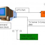
I’m on a journey to build a smallish wifi-controlled, wheeled robot equipped with a VIA mini-itx board (http://www.via.com.tw/en/products/embedded/ProductDetail.jsp?id=81 ) I have laying around. I’m still lacking a few components (batteries, PSU for the VIA), but things should be coming along now. That paper has been a great source of inspiration so far : http://www.scribd.com/doc/31583000/IED-Tech-Report-Final
I tried using a mini itx board myself, but the power consumption killed the project. See: http://www.pocketmagic.net/?p=520 , Perseus 2.
What about an alyx board? Much better than itx but not as good as a phone.
I’m happy with the phone: http://www.pocketmagic.net/?p=1398
Actually things aren’t working exactly as they should. I just found out that the bridge won’t provide more than 1.15A (@ 11.5V). To narrow down the problem I setup a darlington pair with a MJE3055T and a 2N5551 on a breadboard. I found out it wouldn’t provide more than 1.4A. In comparison, the motor draws 2.4A in the same setup, when plugged directly to the power supply. I also tried feeding the signal from a 5V power supply, to be sure it wasn’t being PMW’d. No difference. The breadboard doesn’t appear to be the limiting factor. Could a component possibly be defective? I’m guessing I’m getting off topic, but I would appreciate any help!
radu,
hi, i’ve built your schematic using tip35c/36c..
i’m trying to control a scooter motor, which is 24v 280w using arduino dueminalove.
the problem is this, the motor does’nt even move or make a sound. i’ve already double check the schematic and 100% sure its right..
my code is working on an h-bridge shield (which is only 2a) driving a small motor, but when i test it on your h-bridge it does’nt work..:(
any help would be appreciated..
or maybe can i test your code please?
thanks a lot and more power..
Okay I’ve got my problem figured out. After reading a few pages about transistors and reading my datasheets, I found out that the MJEs weren’t fed enough base current to provide more than about 1.15A with R1 and R2 being 1k. That’s why they were heating; they weren’t fully open.
I thus removed R1 and R2 and my H-bridge now peaks at more than 10A (multimeter won’t go higher).
By the way, I also figured 2N5551 are barely powerful enough to provide sufficient base current for the MJEs at more than about 3A. They are getting hot pretty quickly in my current setup. I’ll get more powerful ones whenever they burn.
jonjon: What’s the maximum output of your h-bridge?
@Victor: excellent feedback
Radu,
Very informative and useful site and I have built this H-Bridge myself over the past few days.
It is working almost 100% with a windscreen wiper motor however I cannot get fullspeed rotation in both directions.
One direction I can pull 4.5 amps and get fullspeed rotation however in the other direction I can only pull about 2.5 amps. I have checked and double checked my circuit and replaced R1 and R2 resistors as mentioned by Victor.
Since this schematic is symmetrical, is there something I am overlooking that would stop the two sides performing the same as eachother?
Thanks for any help.
Nick
Nick,
Perhaps the motor runs better in one direction than in the other? Have you tried running it without the bridge?
I’ve read that in some motors, the case and one wire are common. Perhaps your motor is sitting on some conducting surface, causing a small short ..?
Victor,
Thanks for your reply. I found my problem after comparing the base currents of the two 2955s and finding them to be different. From there it could only be my amplifying transistors causing the difference. I followed this all the way back to the servo inputs. After switching INPUT1 and INPUT2 the halfspeed motor direction reversed itself, so I concluded that there was a problem with the servo wiring.
Sure enough after resoldering the input wires from the servo motor pads, it is now working 100%.
Small mistake, but I’m glad it wasn’t an error in the Bridge.
Hi folks
I am interested in learning about how to forward,and reverse 12VDC permanent magnet linear actuators using an H bridge.
I want my linear actuator to reverse in opposite directions hourly or may be every two hours.
Radu you are the my only hope at the moment.I can see pictires of six different H bridges at this website.Radu ,which of them is the simplest(requiring simple parts) and least expensive to build .
My name is Wisdom Kwame from Ghana in West Africa .If i am successful,i want use the H bridge to forward/reverse a 12VDC ,(no loaad)0.8-5Amp(max load) linear actuator.The braking/stopping of the linear actuator by the H bridge is not needed/required.
Radu kindly give me a step by step guide on how to build the H bridge successfully using simple components like transistors,diodes, and resistor etc because these are the only parts available in my country.It impossible to find even a 555 IC at the best electronics shop in town.
Hi Kwame, I’m extremely happy to see a reader from Ghana.
The pictures of different H Bridges are variants created by some of my readers, but they are implementations of the same design.
You will need to follow the schematics presented in the article (direct link: http://www.pocketmagic.net/wp-content/uploads/2009/03/hbridge-radu1.jpg )
You will need:
2x NPN Power transistors (can be any, I used MJE 3055),
2x PNP Power transistors (fell free to replace, I used MJE2955)
4x Diodes (I used fast diodes BYV26E, they protect the transistors it will work without them too)
4x 1K Resistors (Please read the comments to see other users findings on these values)
2x Generic NPN transistors (I used 2n5551, feel free to put any other)
As you can see there are no critical components in this design. Feel free to post any questions if needed.
I am building your Hbridge to drive a wiper motor to use as a steering servo in a custom RC car. I have double checked my wiring a few times, the only different component I have used are the diodes, they seem to be much larger than specified, 1000V 6A. When i apply power to the circuit MJE2955T become very hot instantly. Are the diodes the problem? I know very little about componenents but I need to get this up and running so help would be great!!!!!!!!!
Hi Craig, Your diodes should be fine.
You will need to triple check your implementation, you did a mistake somewhere.
You can read the comments above, there were some users that did a few mistakes such as:
– incorrectly connecting the transistors: the two on left side share collectors, the other two on the right share they collectors as well,
– incorrect power transistors type: there are 2 NPN and 2 PNP + 2 general purpose NPN command transistors (2n5551)
– etc
Hello. To get straight to it, I’m building a robot using an arduino as the the microcontoller. In addition I am also using an ultrasonic range sensor so that when its finished, the robot will avoid walls.
Now my question is what am I doing wrong when I construct this H-bridge. I’m using an old RC car as the frame with the motor supplied which runs on a 3V battery. I’m in high school and don’t really have much money so I had to scavenger components around me. I tried the schematic on my breadboard and turned out unsuccessfully; nothing happened to the motors, no hum or anything. Is this because I’m using a transistor without a heat sink? I was going to plan on getting one once I see that the circuit is functioning properley.(I wasn’t planning on using the transistor with no heat sink at that moment because I just wanted to see if it worked). Or does the problem lye on this situation that I’m supplying this circuit with 3V+. I appreciate your help. This is the first I’ve constructed a robot and I have been stuck for a while with controlling the direction of the motor. Below are the transistors I used:
4 NPN 3904 M804
2 PNP 3906 439
Thank you for your help.
Hi
I need an H-bridge circuit that could handle 18A current. Which diodes and Transistors to use.
Thanks
Hey, I wanted to give you a small update on my project using your h-bridge.
Pics : http://img.campouze.org/zqX/IMGP7480.JPG
http://img.campouze.org/NiF/IMGP7489.JPG
http://img.campouze.org/mD1/IMGP7491.JPG
I took the pictures juste after a crash so you may notice a few things gone wrong.
Now that I started to test it for real, a small transistor of the bridge fried. I’m thinking about upgrading these but the big ones do seem to get pretty hot too so I may end up making a whole new h-bridge.
By the way, I’m happy with the mini-itx platform so far. I bought a 14.8V 5Ah LiPo battery for dirt cheap (cheaper than NiMh, can you believe it?) on HobbyKing. Should last a couple of hours.
Anyway, I’m thinking about overhauling the whole chassis and giving it bigger wheels. It can’t really handle any fancy ground right now. Also thinking about getting another motor; the windshield wiper motor is powerful enough but is rotating too quickly in this setup (hence the crash, heh). I might want to keep the gearbox next time.
Good luck with your projects!
friend,
i m making a bot for robowars and was using DPDT switches to control my movement…
later did i come to know about the h bridges ..!i already have an arduino board with me .. but am unable to make out how to use the H bridge …
please help ..
the motors i am using to drive my 4 wheel drive bot is (12V/9.5A{stall current}each)
should i make the circuit u have shown above exactly ??
@Daniel, using different transistors is fine, but you need to check their parameters to see how the two commanding transistors (in my diagram the two 2n5551) will work with your small voltage. I can’t find the datasheets of what you used, can you provide some links for that?
@Salman, you can use several transistors in parallel, but with small resistors (0.5Ohm) on emitters.
@Victor: great to see you’re using a mini itx board. I’ve also tried, but had some serious problems with power consumption. Maybe my batteries where not good. The transistors shouldn’t get very hot. Double check the schematics, you might have an error.
@Shashank: the HBridge uses a voltage input (two wires for your 12V battery), two logical inputs (small 5V commanding voltage ) INPUT1 and INPUT2, and the motor output. When you send a 5V voltage on input one, the motor output gives you +-12V and the motors works in one direction. When you send 5V on input two, the motor gets -+12 V so the motors reverses direction. So for each motor where you need to be able to reverse polarity, you will need one HBridge, such as the one presented in my article.
After a couple of attempts I have made my H bridge to work.
I have put two on the one board, one side is very messy but the second is alot better.
I only use a resistor on the base of each 2N5551 because the wiper motor was very slow
to turn with the additional resistors.
All of the MJE transistors get very hot quickly but with the heatsinks and an old computer fan it stays nice and cool.
I am using it to drive a windscreen wiper motor and a power window motor acting as steering and throttle/brake servos for a large scale RC car I am building.
http://i1233.photobucket.com/albums/ff381/cd600/Custom%20RC%20car/topcircuit.jpg
http://i1233.photobucket.com/albums/ff381/cd600/Custom%20RC%20car/bottomcircuit.jpg
http://i1233.photobucket.com/albums/ff381/cd600/Custom%20RC%20car/windowwindermount.jpg
Thank you Radu, your page has been a great help to my project.
hey guys i made this h-bridge and it works great except i think my code is shorting it. can anyone help me out with it?
int left = 10;
int right = 6;
void setup()
{
pinMode(left, OUTPUT);
pinMode(right, OUTPUT);
}
void loop()
{
for (int k=0; k<5; k++)
{
for (int i = 0; i<30; i++)
{
analogWrite(left,255);
delay(830);
analogWrite(left,0);
delay(10);
analogWrite(right,255);
delay(830);
analogWrite(right,0);
delay(10);
}
delay (4000);
}
delay (10000);
}
That was neat and nice design of H bridge circuit. I found so many designs in the internet, but this was very simple to learn and design. Thanks to author.
Pingback: Android controlled rower robot – Part 2 « PocketMagic
Pingback: Dual H-Bridge for controlling two motors « PocketMagic
Hi Radu,
I have only one question. What will happen if I won’t connect the right (and left) transistors in the same heatsink? I have designed a PCB that uses four different heatsinks. Will the H-Bridge still work?
Best regards,
Gear_Clinkz
Yes, it will work. Send me a few pics when it’s done, I’d love to see your variant.
Ok I will!
Thank you for answering!
Gear_Clinkz