
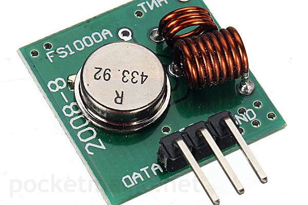
Wireless data transfer can be useful for a variety of projects. I stumbled upon a very low cost emitter+receiver modules pair, and planned to use it for some time now. There are a few variants available on the market, but they do quite the same thing, just the operating frequency might be different (315MHz / 418MHz / 433MHz/ 915MHz):

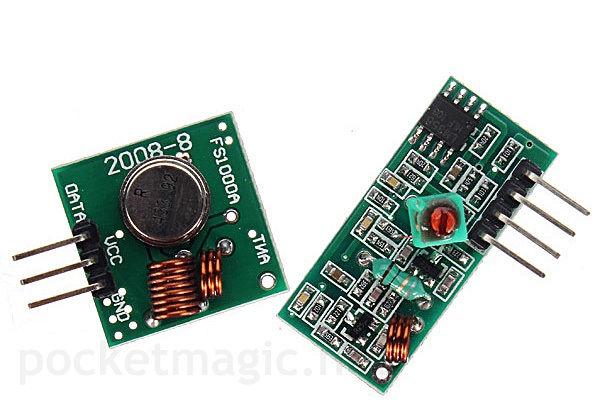
The emitter usually has 3 pins (VCC->5V, GND, DATA), with a few variants that expose the fourth pin for connecting an external antenna to increase the range. The input voltage interval is 3.5-12V (the higher the voltage, the longer the range, usually between 20-200m).Size 19x19mm, operating mode AM, transfer rate 2400bps.
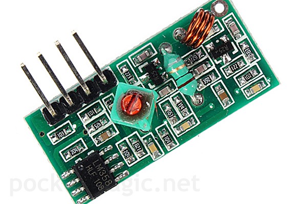
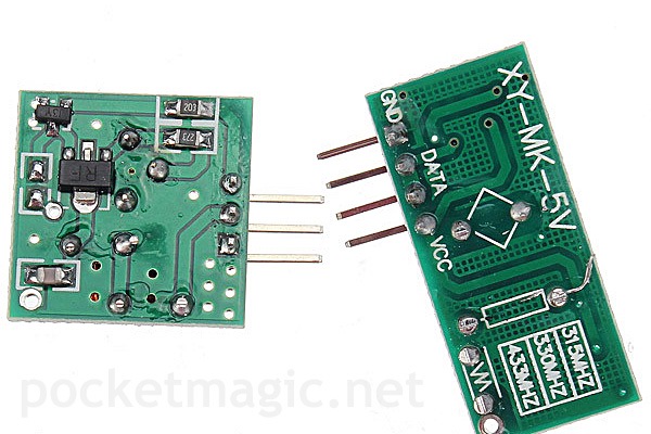
The receiver also has three pins (VCC, GND, DATA) and it operates at 5V. It uses only 4mA. The sensitivity is -105DB, and the module size 30 * 14 * 7mm.
How to use the FS1000A / RF Modules
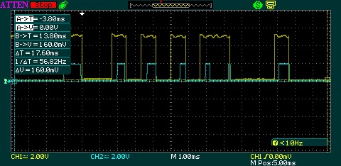
Setting the emitter’s DATA pin to HIGH will result in a radio transmission that will set the receiver’s DATA PIN to high. By doing so, it is obvious that a serial connection can be implemented, once a common baud rate has been defined. We’ll push bits to the transmitter’s DATA Pin, assuming we are in the supported baud rate interval, and the receiver will get the data we’ve sent over the radio (plus errors). Here is the signal on transmitter’s pin (CH1/yellow) and the signal collected at the receiver (CH2 / cyan):
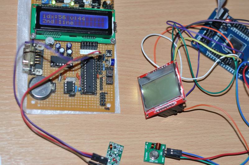
This shows that all we have to do is to hook the emitter to the AVR’s UART TX port, and the receiver to another AVR’s UART RX Port. We write some code to initialize the UART ports using the same baud rate, and we’re ready to exchange data. Here is a sample setup , with receiver connected to an Atmega8 board, showing data on a 2×16 LCD, and the emitter’s board with an Atmega128 and a Nokia 5110 LCD. The numbers on the two LCD’s match, as what this setup does is to increment an integer every second, and send it over the radio. So what we see on the 5110 LCD, we also see as V: number on the receiver’s screen.
The problem here is we are getting lots of errors, and the emitter module will not know if the transmission was successful or not (because it is unidirectional communication). The simple code implementation is:
the emitter code
uart0.Init(0,1200, false); // init uart0 for 1200bps baudrate, no RX callback
while(1) {
	i = (i+1) % 256;
	led1.Toggle(); led2.Toggle();
	uart0.Send(i);
	lcd.goto_xy(0,0);
	lcd.send_format_string("%d ", i);
	_delay_ms(1000);
}
the receiver code
uint8_t v = 0;
ISR(USART_RXC_vect){
	 volatile char c = UDR; //Read the value out of the UART buffer
	 v = c;
}
...
main() {
uart0.Init(0, 1200, true); // init uart0 for 1200bps, with RX callback
int i = 0;
while(1) {
	i++;
	lcd.lcd_cursor_home();
	lcd.lcd_string_format("idx:%d v:%d     \n2nd line  ", i, v);
	_delay_ms(1000);
}
This works fine, but from time to time, the receiver picks up random bits, leading to wrong data. There’s also the problem of multiple module pairs working in close proximity causing interference, or the problem of missing some of the data (the receiver doesn’t get all the bytes transmitted over the RF link).
Like in similar serial data communications, we can assign an address to differentiate between multiple devices, and compute a checksum value to rule out some of the errors (building data packets). This is a good solution, but we still have the problem of loosing some of the packets, and because the communication is unidirectional we can’t inform the emitter to retransmit. Unfortunately this is as good as it gets, so keep this in mind when using these modules, as they are not intended for precise data transmissions.
the emitter code
UART uart0;
//define receive parameters
#define RADDR 0x10 // common address parameter
void Send_Packet(uint8_t addr, uint8_t cmd) {
	uart0.Send(addr);//send receiver address
	uart0.Send(cmd);//send increment command
	uart0.Send((addr+cmd) % 256 );//send checksum
}
...
main() {
uart0.Init(0,1200, false); //uart0:
int i = 0;
while(1) {
	i = (i+1) % 256;
	led1.Toggle();
	led2.Toggle();
	Send_Packet(RADDR, i); // send packaged byte
	//uart0.Send(i); //send unpackaged byte
	lcd.goto_xy(0,0);
	lcd.send_format_string("%d ", i);
	_delay_ms(1000);
}
the receiver code
#define RADDR 0x10 // common address parameter

// we can't know in which order we get the bytes of a package
// so we use a circular buffer with 3 positions
uint8_t buf[3], ind,  v;

ISR(USART_RXC_vect){
	volatile char c = UDR; //Read the value out of the UART buffer
	//v =c; // unpackaged byte
	// add the byte to the circular buffer
	buf[ind] = c;

	// we don't know which is the first byte of our package,
	// so we check the circular buffer, testing each byte for the start condition
	for (int i=0;i<3;i++) {
		uint8_t raddress, data, chk;//transmitter address
		raddress = buf[(0+i)%3];
		data = buf[(1+i)%3];
		chk = buf[(2+i)%3];
		if (chk == ((raddress + data)%256))
			v = data;
	}
	// increment the circular buffer index
	ind = (ind + 1) %3;
}
..
main() {
uart0.Init(0, 1200, true);
int i = 0;
while(1) {
	i++;

	lcd.lcd_cursor_home();
	lcd.lcd_string_format("idx:%d v:%d     \n2nd line  ", i, v);
	_delay_ms(1000);
}
The algorithm works much better than the first, as now we won't get those random bytes picked up by the receiver. And because of the RADDR identifier, we can use several such modules in close proximity, as we now know which packet is intended for which receiver.
Resources
KLP Walkthrough
Running TX433 and RX433 RF modules with AVR microcontrollers
Source code
This is only a simple UART implementation, but you might find the data package logic useful:
FS1000A_Radio

Pingback: Kickstarter: Global radiation monitoring network « PocketMagic
thank you for this circuit diagram regulated power supply but i can not find some divaice for make
Pingback: ESP8266 Troubleshooting - PocketMagic
dear sir.
Is it possible to use two emitter+receiver modules pair in each side to make bidirectional communication and solve the problem of transmitters errors?
yes
Hi Radu – I am new to this RF and got the transmitter and receiver and make a test, – you write “Setting the emitter’s DATA pin to HIGH will result in a radio transmission that will set the receiver’s DATA PIN to high”
– so I put the datapin to high and the datapin on the receiver go high but only short time – then it go low again even the transmitter datapin is high – when I set it low and high again the same happen in the receiver !???
Have I miss understand you ? I thought that while the datapin on the transmitter then the receiver pin also will be high all the time !
Can you please clear this for me ?
Best regards Erik
Hello Erik,you can see the idea on the oscillogram included. The idea is to send sequences of 0’s and 1’s. You define the baudrate. You define how long to wait to register a 1 or a 0. As you can see, it works pretty well, since I was able to use existing UART code. Hope this helps.