
“Ultraviolet (UV) light is electromagnetic radiation with a wavelength shorter than that of visible light, but longer than x-rays, in the range 10 nm to 400 nm, and energies from 3 eV to 124 eV. It is so named because the spectrum consists of electromagnetic waves with frequencies higher than those that humans identify as the color violet.” Source.

There are several ways of subdividing the UV electromagnetic spectrum. Most common is:
| Name | Short | Wavelength | Photon energy |
| Ultraviolet A, long wave, or black light | UVA | 400 nm–320 nm | 3.10–3.94 eV |
| Ultraviolet B or medium wave | UVB | 320 nm–280 nm | 3.94–4.43 eV |
| Ultraviolet C, short wave, or germicidal | UVC | 280 nm–100 nm | 4.43–12.4 eV |
There are several ways of producing UV light, that include natural sources (Eg. the Sun) or artificial sources (UV bulbs, UV tubes, N2 Lasers, etc).
I have tested two UV Light tubes: a black light UV tube, and a germicidal UV tube. There two correspond to UVA and UVC spectrum.
UVA
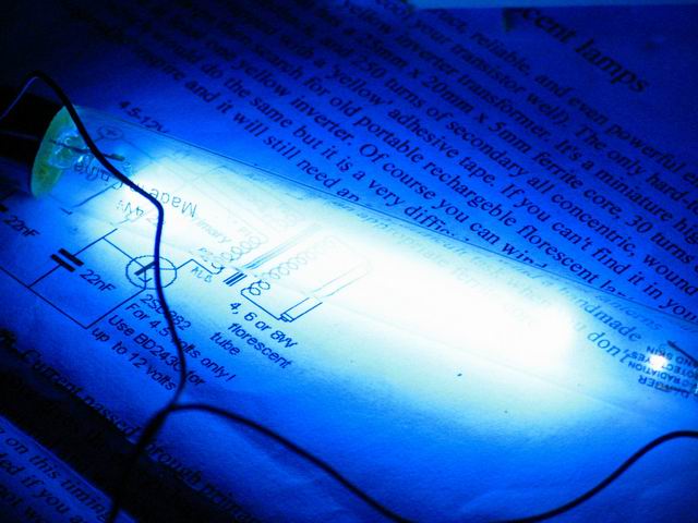
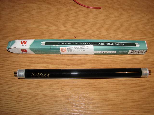
The wavelength is in the range of 400 nm and 320 nm. I have a 6W “blacklight tube”. Looking at powered tube you barely see anything, but putting a piece of white paper shows powerful fluorescence. The second picture below shows this phenomenon:

The reason for this is that my UVA tube emits long wave UV radiation and very little visible light.
In the third picture, the glass ball is an uranium doped glass. It shows greenish fluorescence when exposed to UV. See an article on this topic, here.
This type of tube looks black when non energized, as the deep-bluish-purple glass called Wood’s glass, is a nickel-oxide–doped glass, which blocks almost all visible light above 400 nanometers.
Unlike the other UV subdivisions with shorter wavelength, the UVA emits lower energy radiation, that doesn’t cause sunburns or skin cancer. Instead, UVA is capable of causing damage to collagen fibers and destroying vitamin A in skin.
UVC
I got these tubes at a fair price on Ebay. They were manufactured to be used in germicidal applications. Most of the light they produce is in the 280 nm–100 nm spectrum. The sun is a natural source for UVC radiation. Some of the UVB and UVC radiation is responsible for the generation of the ozone layer. After running my UVC tubes for a while, ozone smell could be detected in the air surrounding the tube.
In this video you can see that if the magnetic field moves, the plasma moves in such a way that magnetic field lines cannot slide across the plasma.
UVC rays are the highest energy, most dangerous type of ultraviolet light. Unshielded exposure of the skin or eyes to UVC light sources is quite dangerous. It can produce DNA damage that leads to skin cancer, since it penetrates the skin, so protection is required.
 |
 |
 |
Power source
Solution 1:
To power these tubes you need a high voltage source. A simple solution is to use an inverter. You can also build one, using a power transistor (2n3055) and a flyback transformer ferrite core:

The resistors need to be at least 5W, and the transistor can be a 2n3055.
The primary consists of 30 turns, for the feedback you’ll need 15turns and 250 turns of secondary, all concentric. You might need to be able to swap feedback (or primary) connections in case of wrong phase polarity.
Solution 2:
Another way of building the power source is without a feedback coil, but instead a 555 timer to trigger the power transistor. Here are the schematics:

Instead of the MPSA42 / MPSA92, you can use any other generic PNP/NPN pair of 0.5A minimum current.
The Mosftet (IRF540) will be needing a heatsink. You can use a different power mosfter or a power BJT transistor instead (eg. 2n2055).
The secondary can be winded manually or you can use a flyback secondary.
The advantage of this circuit is that you can adjust the frequency using the pot.
The next few days, I’ll be publishing an article on various high voltage sources, so we’ll see more on these later.
Radu Motisan


Hey there:D
Nice site you’ve made here! I really like the schematic based on the 555 timer. It’s quite simple, though extremely applicable! Good thing to be able to adjust the frequency. I’ve been looking around the net for a circuit like this for quite some time now, thanks maid;)
Keep the electrons in flux!
X
maid :)))
I’m glad you find this site useful. Come back any time.
Thank you for this great project,, but theflyback transformer has only 2 terminalsfor primary and 2 for secondary,, u r using 6 !!! how is that ??
Thank you for thisreally great website,, but the flyback transformer has only 2 terminals for primary and 2 for secondary,,u r using 6 terminals.
another thing,, i need a high votage source (10-15KV) in order to make an N2 laser,,which circuit do you advice me to use ??
thanks man for this great site
hi Hazem, thanks.
The primary consists of 30 turns, for the feedback you’ll need 15turns and 250 turns of secondary, all concentric. You might need to be able to swap feedback (or primary) connections in case of wrong phase polarity.
May I ask an extremely silly question ??? Is the output of the flyback DC or AC ???
Hi Radu,
I have a 45W UVC lamp and would like to use your circuit to power it to reduce dust mites – can you recommend how components need to be scaled for higher wattage?
Best
hG
@Hazem, in the video the output is DC.
@hg, interesting idea. I would suggest you build a ZVS driver : it can run for long without getting even warm, and handles 200W:
http://www.pocketmagic.net/?p=311
For optimal performance, you need to build it on the mosfet connectors like in this picture:
http://www.pocketmagic.net/wp-content/uploads/2009/01/img_1805.jpg
Thank you Radu,
Do you have one that would produce the frequencies of 254 nm with a varying power?
Best
Hg
What some one needs to do is make a website that has the basic circuits to help people get started EG: a Radio transmitter and receiver and PWM a bit like your Ultraviolet Light Solution 1
Let me know if you need help. But believe me when saying that the best thing with these inverters and their coils is to start experimenting: after wasting a few hours and a few non-working coils – you’ll know everything you need to get some great results.
Awesome circuits–thank you for the 555 schematic. I built a 2 flyback 10cm super HV supply. It’s a ZVS using 2 mosfets (IRFP250). I would recommend you add a 0.1uF capacitor and a 10k resistor to further reduce possible kickback in the 12V line of the power supply. I plan to try your method with a 555. I have built other timer circuits before, but did not build my duel flyback with it for fear the very high voltages (over 100kv-150kv!) would cause the chip to fry. It might work, but the ZVS gives really clean DC out which is what I needed. Cool UV stuff! I like the clear UV bulbs. Unlike what many said in forums–it is possible to run 2 flybacks in series! I have the proof in pictures and video on my blog– “Mostly Macros” or (http://gabebeas.blogspot.com)
Gabe Beasely
Mostly Macros photography
you’ve got a nice blog. love your macro shots!
i have decided to make a flyback transformer for a science project, and i am not so great at this area. for solution 1 (the one i am doing) what exactly do the capacitors do? i need to know this for my write-up.
i have seen many other circuits like this one, only they don’t use the capacitors; would i still be able to light up a uv light without them?
yes, the inverter will work even without the capacitors.
hi ….I like your 555 flyback driver…I also use a neon light to protect
by powersupply from back emf.
I’m curious about the use of the pnp and npn transitors in push pull configuration.
I’ve been able to drive an IRF 250 mosfet with just the 555 output, 0~7 or 10 VDC.
How does the push-pull help and is the 540 a much better choice…?
thanks !