
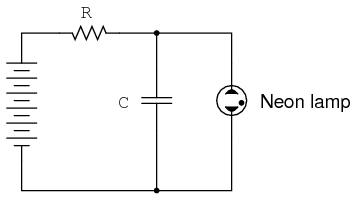
Oscillators are electronic circuits that produce an oscillating (AC) voltage from a steady supply of DC power. A relaxation oscillator is one that works on the principle of a charging capacitor that is suddenly discharged every time its voltage reaches a critical threshold value. One of the simplest relaxation oscillators in existence is comprised of three components (not counting the DC power supply): a resistor, capacitor, and neon lamp.
Neon lamps are nothing more than two metal electrodes inside a sealed glass bulb, separated by the neon gas inside. At room temperatures and with no applied voltage, the lamp has nearly infinite resistance. However, once a certain threshold voltage is exceeded (this voltage depends on the gas pressure and geometry of the lamp), the neon gas will become ionized (turned into a plasma) and its resistance dramatically reduced. In effect, the neon lamp exhibits the same characteristics as air in a lightning storm, complete with the emission of light as a result of the discharge, albeit on a much smaller scale.
The capacitor in the relaxation oscillator circuit shown above charges at an inverse exponential rate determined by the size of the resistor. When its voltage reaches the threshold voltage of the lamp, the lamp suddenly “turns on” and quickly discharges the capacitor to a low voltage value. Once discharged, the lamp “turns off” and allows the capacitor to build up a charge once more. The result is a series of brief flashes of light from the lamp, the rate of which is dictated by battery voltage, resistor resistance, capacitor capacitance, and lamp threshold voltage.
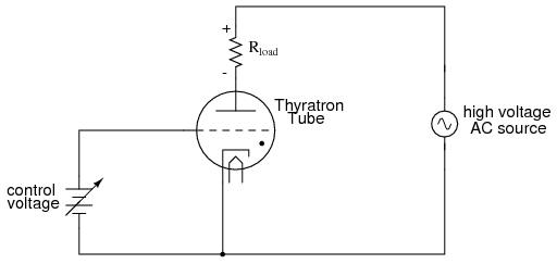
While gas-discharge lamps are more commonly used as sources of illumination, their hysteric properties were leveraged in slightly more sophisticated variants known as thyratron tubes. Essentially a gas-filled triode tube (a triode being a three-element vacuum electron tube performing much a similar function to the N-channel, D-type IGFET), the thyratron tube could be turned on with a small control voltage applied between grid and cathode, and turned off by reducing the plate-to-cathode voltage.
In essence, thyratron tubes were controlled versions of neon lamps built specifically for switching current to a load. The dot inside the circle of the schematic symbol indicates a gas fill, as opposed to the hard vacuum normally seen in other electron tube designs. In the circuit shown above the thyratron tube allows current through the load in one direction (note the polarity across the load resistor) when triggered by the small DC control voltage connected between grid and cathode. Note that the load’s power source is AC, which provides a clue about how the thyratron turns off after its been triggered on: since AC voltage periodically passes through a condition of 0 volts between half-cycles, the current through an AC-powered load must also periodically halt. This brief pause of current between half-cycles gives the tube’s gas time to cool, letting it return to its normal “off” state. Conduction may resume only if enough voltage is applied by the AC power source (some other time in the wave’s cycle) and if the DC control voltage allows it. (source)
The thyratron cool down time (also called recovery time) is a process in which the ionized gas inside looses electric charge and returns to neutral state. The time required is strictly dependent on the gas used inside the tube. To achieve short deionization times, hydrogen and deuterium are used. A short deionization time means that the tube is getting ready for another pulse faster, resulting in higher operation frequency and oscillator frequency. Here are some examples:
3C45 Hydrogen Thyratron: 0.6usec deionization time
8503 Hydrogen Thyratron: 5-40usec
309CE / FG17 Mercury Vapour Thyratron: 1000usec!
3C31 / 5664 / ELC1B Xenon gas Thyratron: 500usec
Turning OFF a Thyratron working with AC current is easy. If the thyratron conducts on one alternation, the next alternation will turn it off. It is a different story when the Thyratron uses DC High voltage, and this is the most common case. Instead of the simple capacitor in the relaxation oscillator diagram, a pulse forming network is used. PFN has inductive properties so the positive discharge voltage has a tendency to swing negative, turning the thyratron off and ready for the next discharge.
This kind of approach has been used in radars, and Radartutorial.eu has a very good article describing the functionality details : ”

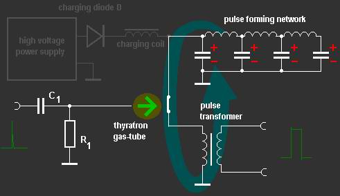
Radio frequency energy in radar is transmitted in short pulses with time durations that may vary from 1 to 50 microseconds or more. A special modulator is needed to produce this impulse of high voltage. The hydrogen thyratron modulator is the most common radar modulator. It employs a pulse-forming network that is charged up slowly to a high value of voltage. The network is discharged rapidly through a pulse transformer by the thyratron keyer tube to develop an output pulse, The shape and duration of the pulse are determined by the electrical characteristics of the pulse-forming network and of the pulse transformer.
As circuit for storing energy the thyratron modulator uses essentially a short section of artificial transmission line which is known as the pulse- forming network (PFN). Via the charging path this PFN is charged on the double voltage of the high voltage power supply with help of the magnetic field of the charging impedance. Simultaneously this charging impedance limits the charging current. The charging diode prevents that the PFN discharge himself about the intrinsic resistance of the power supply again.
The function of thyratron is to act as an electronic switch which requires a positive trigger of tens or hundreds of volts. The thyratron requires a sharp leading edge for a trigger pulse and depends on a sudden drop in anode voltage (controlled by the pulse- forming network) to terminate the pulse and cut off the tube. The R-C Combination acts as a DC- shield and protect the grid of the thyratron. This trigger pulse initiates the ionization of the complete thyratron by the charging voltage. This ionization allows conduction from the charged pulse-forming network through pulse transformer. The output pulse is then applied to an oscillating device, such as a magnetron.
The Charge Path
The charge path includes the primary of the pulse transformer, the dc power supply, and the charging impedance. The thyratron (as the modulator switching device) is an open circuit in the time between the trigger pulses. Therefore it is shown as an open switch in the Figure:

Once the power supply is switched on (look at the dark green voltage jump in the following diagram), the current flows through the charging diode and the charging impedance, charges the condensers of the pulse forming network (PFN). The coils of the PFN are not yet functional. However, the induction of the charging impedance offers a great inductive resistance to the current and builds up a strong magnetic field. The charging of the condensers follows an exponential function (line drawing green). The self- induction of the charging impedance overlaps for this.
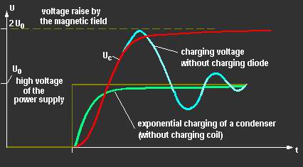
UC = U0 ·( 1 – cos ωr· t)
ωr^2 = 1 / LDr · ΣC
If the condensers are charged with the power supplies voltage, decreases the current and the magnetic field breaks down. The breaking down magnetic field causes an additional induction of a voltage. This one continues the charging of the condensers up to the double voltage of the power supply. Now the condensers would discharged (ice blue curve) about the power supplies resistance, but the charging diode cut off this current direction and the energy remains stored therefore in the condensers.
The Discharging Path
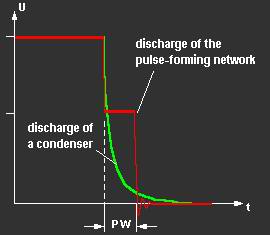
When a positive trigger pulse is applied to the grid of the thyratron, the tube ionizes causing the pulse-forming network to discharge through the thyratron and the primary of the pulse transformer. (The tyratron is „fired”)

The fired thyratron grounds the pulse line at the charging coil and the charging diode effectively. Therefore, a current flows for the duration PW through the pulse transformer primary coil to ground and from ground through the thyratron, which is now conducting to the other side of the pulse forming network. The high voltage pulse for the transmitting tube can be taken on the secondary coil of the pulse transformer. Exactly for this time an oscillating device swings on the transmit frequency. Because of the inductive properties of the PFN, the positive discharge voltage has a tendency to swing negative.
If the oscillator and pulse transformer circuit impedance is properly matched to the line impedance, the voltage pulse that appears across the transformer primary equals one-half the voltage to which the line was initially charged.
” (source)
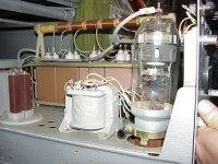
A DIY Relaxation oscillator using a Hydrogen Thyratron
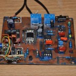
To test the working principle, I have designed a relaxation oscillator using the following:
– high voltage DC supply (using a 100W flyback transformer, and a Royer push and pull oscillator), providing 8KV 10mA.
– rewound mot supply , for tube filament
– a ferrite choke for charging the PFN
– a pulse forming network, as presented here.
– a hydrogen thyratron, TGI2 400/16
– a 200V pulse generator, more details here.
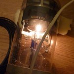
For a test load I have used an air transformer (tesla coil). This would be my first Thyratron Tesla Coil (THYTC). And here are the results:
TGI1-400/16 is a bad choice. Try to find TGI1-400/3,5 that more appropriate for domestic exprements.
This thyra’ns can hold above 40 kHz pulse and switch in a megawatts at pulse.
привет!
Unfortunately I don’t know where to find the 400/3.5
Pingback: Thyratrons - PocketMagic