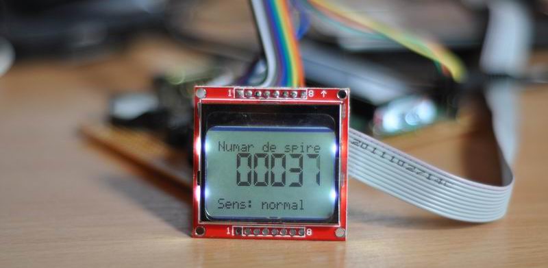
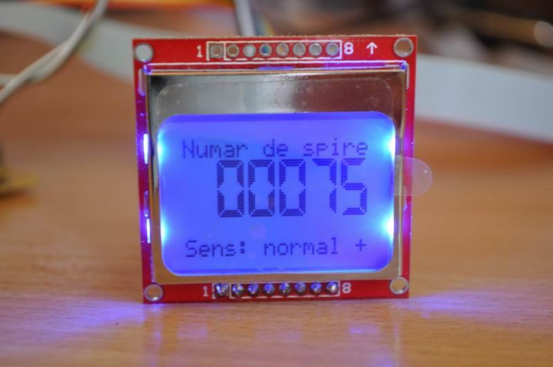
Ovidiu asked me to build a digital counter for his new project, a coil winding machine. Here is what I came up with:
Variant 1 : Atmega8 + Nokia 5110 LCD + 3V power supply
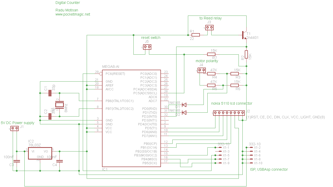
I am using an Atmega8-8PU (configured for 8MHz with external crystal), a Nokia 5110 lcd, and a transistor to handle the pulses from a reed relay. A 3.3V regulator provides the voltage for the entire circuit.
Everything has been mounted on a test board, including the headers for: ISP programmer (USBAsp), the 5110 Nokia LCD, the power supply (5V in, fed to the 3.3V regulator), the Reed relay connector, the reset button connector and another 2 pins connector, used to read the polarity of coil winding machine’s motor, so we know we either increment or decrement the counter.
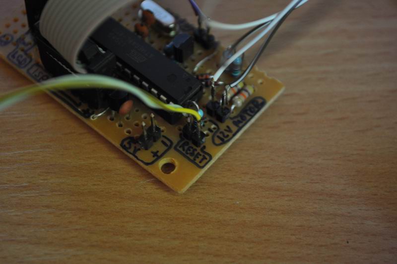

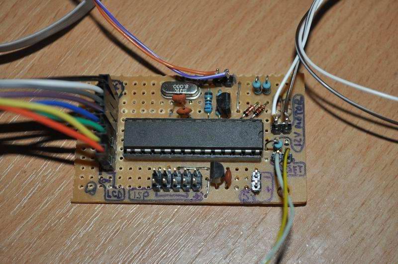
There are a few connectors:
J1: is for the power supply. The circuit takes 5V, that get into the L7833 for 3.3V output used by the atmega8 uC and the LCD.
J2: is the LCD connector, going to the Nokia 5110LCD.
J3: goes to the reed relay. This is the place we generate pulses for the microcontroller to count.
J4: is the polarity connector. It must be connected in parallel on the coil winding machine’s motor. It was designed for a 12V motor (but this can be changed by adjusting the voltage dividers formed by R3-R4 and R5-R6, so they take in the motor voltage, and output not more than 5V). If the motor is connected in normal polarity, we will read PD0 high, if the motor is in inverse polarity, we’ll have PD1 high. This info is used in the code to either increment or decrement the counter.
J5: is just a simple momentary switch. When pressed, will reset the counter to zero.
ISP connector: is a 10 pin connector used with the USBAsp AVR programmer.
Circuit diagram:
Fuse bits:
External 8MHz crystal. The settings are:
avrdude -p atmega8 -c usbasp -U lfuse:w:0xff:m -U hfuse:w:0xc9:m
Source code:
You can download and use the source code, under the Apache license, here.
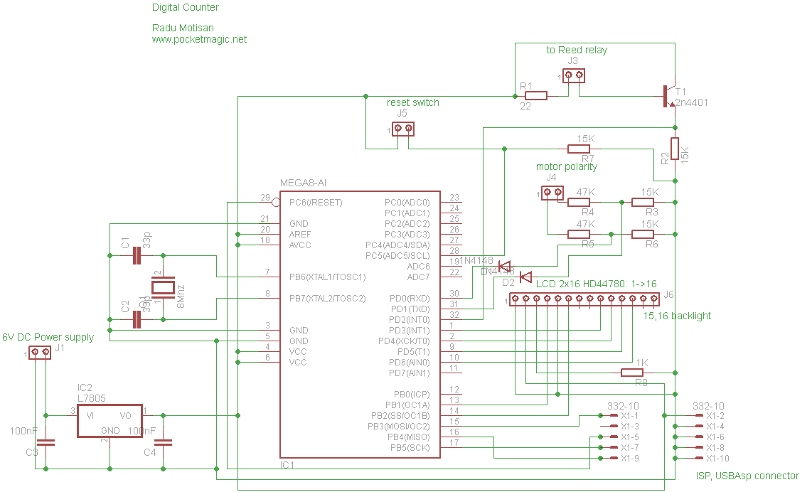
Variant 2 : Atmega8 + 2×16 HD44780 Character LCD + 5V power supply
Some of my readers asked for a custom variant, that uses a 2×16 HD44780 LCD (or a 1×16 smaller variant). These displays require a 5V voltage supply, so here is variant 2 of the digital counter, modified to support these requirements.
2×16 LCD Circuit Diagram:
Hex file, SCH and source code:
Can be downloaded here: atmega reed digital counter 2x16LCD
I am trying to understand something, you used a atmega8 that only has 28 pins and in your schematic it shows 32 pins. Ok I am not getting this, pin numbering you got going on here can you please email me with the needed info and how to change it to english.
Thank you
Email me at areyoukiddingme31@ymail.com with coil counter in subject line thank you
That is because I included the SMD version of the Atmega8 in the SCH. So just use the 28 pins DIP Version instead.
OK, Thank you. Now can it be changed to English? It’s a great design by the way been working on something like this for a few months now, and seen this, it’s a great example thank you for sharing this.
The source code has been provided at the bottom of the article, you simply need to change the texts and recompile the code. But if you need help, I can do it for you and simply post the .hex file here. What do you think?
i need the winding method with its assembly cod and interfacing ,please sent me through email :aregaw145@gmail.com
code for the winding machine
Radu,
Sorry that I haven’t gotten back with you on your answer been very busy . If you could please help me with this that would be great. I have built my coil winding machine using stepper motors, I have done what you said to do by changing the text and recompiling and something is just not right.
Thank you
Jason
Radu,
How could one go about purchasing one of these units (if available)? Alternatively if not available for sale, is there a complete parts list available so I could build it? My experience in electronics is very limited.
Thanks.
Ugo
Please respond to: ucrecco@shaw.ca
Hi there,
Very nice project, one thing (two actually), what schematic/pcb package is the 2x16LCD- version pcb designed and second could you please post the .hex- code for the controller? (…or if not too much trouble email it to me.)
Thank you kindly.
Hans
Radule am construit si eu numaratorul cu atmega 8 si lcd-ul nokia inca nu l-am folosit ca mai trebuie plantat sursa de 3.3v si nu am avut timp sa o comand
Am incercat sa modific intrare impuls de numarare , in loc de reed sa adaptez optic si nu m-ia iesit nu stiu sa lucrez cu microcontrolere , cred ca am depasit valorile
Multam pentru munca ta ….o zi buna …Dan
Apropo revin____sa stii ca montajul tau a fost construit de multi electronisti amatori dar problema este cu releul reed la viteze mai mari este cam “”mototol”___beleaua este ca noi cei mai batrini nu ne pricepem la programari , cu chiu si vai debia am invatat sa folosesc programatorul IC2
hello is freat project,
have any body try to make this in arduino?
i will like to find in arduino nano this can anybody makeit?
in schematic i dont understand where is go the 332-10 all this what is X1-1 X1-2 etc
Dintr-o calculatrice de la dolarama, se poate face numararea spirelor cu afisare.
Dar este mai putin plictisitor with Atmega8 and Reed relay.
Have a nice day!
Calculatrice? Dolarama?
🙂 what’s that?
M-am englezit , m-am frantzuzit… . Imi pare rau ca am fost superficial. Traiesc in Montreal si aici sunt magazine numite “Dollarama”, iar majoritatea marfurilor costa 1$ si ceva, sau mai mult. Cand am spus “calculatrice”, ma refeream la o socotitoare electronica care costa 1$ si care se poate folosi (cu o minima modificare) pentru afisarea numarului de spire in timpul bobinarii. Nu vreau sa intru in detalii, pentru ca imi pare penibil sa expun un asemenea proiect in prezenta unui proiect cu greutate, cum este acesta :
“Coil Winding machine counter with Atmega8 and Reed relay”.
Cred ca mai degraba ar fi mers la instructables.com.
Am incercat sa o dreg , dar am senzatia ca nu am prea reusit.
Oricum ar fi , tin sa precizez ca am o deosebita stima si consideratie pentru munca lui Radu Motisan.
Iti doresc succes !
Salut Marin, am inteles acum , ai dreptate, se pot folosi acele socotitori si pur si simplu folosesti semnalul ca sa incrementezi +1 suma de pe ecran.
Daca ajungi sa faci o pagina pe instructables cu asta, pot sa adaug linkul la acest articol, pentru a oferi mai multe optiuni celor interesati.
Radu
it is possible to do with Arduino Nano and 20×4 display and how?
with 4 wire 5v, SDA, SCL,GND
This LCD display LiquidCrystal _I2C library
http://www.instructables.com/file/FD0IZBVI1T4BNUW/
Please let me now if possible thanks.
Hi Ed, yes it is possible. There are certain changes required. Unfortunately I am caught with other projects and don’t have the time for such modifications. You can either use the LCD I have indicated (it’s no big deal, it is cheap and available), or you can make the changes yourself.
Dear Sir,
good day!!
kindly send us your techno-commercial offer for the
Variant 2 : Atmega8 + 2×16 HD44780 Character LCD + 5V power supply – 1 Set
Hi Radhu,
I’m very much impressed with your digital counter for coil winding machine circuit using Nokia 5110 lcd module. But I’m little bit confused to where I have to connect the other end of the 332 – 10 USBAisp connector. I’ll be much grateful to you if I receive the details in my mail id japnin@yahoo.com
Hi Radhu,
I was just wondering what are the advantages and disadvantages of this digital counter?
It’s just a counter, what are you talking about?
How much does all the components cost to build this counter?
Domnule Motisan,
As vrea sa construiesc “Coil Winding machine counter with Atmega8”, varianta cu display de Nokia 5110.
Acest tahometru este bun, multzumim pentru fisierul .hex, insa eu as dori sa-l adaptez la o masina de bobinat manuala.
Dezavantajul ar fi ca in acest caz sensul contorizarii nu mai poate fi stabilit de polaritatea motorului electric. Mai mult, chiar daca as simula sensul cu un comutator se pune o alta problema:
Atunci cand magnetul este in dreptul contactului magnetic si penduleaza mai mult de 10 gr. inainte sau inapoi, softul contorizeaza ca si cand masina ar efectua o rotatie completa.
Lucrul acesta este des intalnit la masinile de bobinat manuale.
Eu doresc sa adaptez un ansamblu de 2 senzori optici opturati de o “cruce de malta”, secventa de numarare fiind: 00, 10, 11,01 s.a.m.d, repetata de 4 ori pe parcursul unei rotatii complete.
Problema este ca nu prea stapanesc programarea acestui tip de microcontroller ca sa rezolv programul de la zero. Ati avea amabilitatea sa-mi trimiteti sursa programului? Astfel as modifica doar rutina de numarare. Va asigur ca nu voi folosi proiectul pentru beneficii materiale si va voi returna sursa programului modificat cu multzumirile de rigoare.
Cu stima!
D.Sandu
Buna seara Dle. Sandu. Codul sursa e deja oferit celor interesati, sub licenta Apache, mai sus in articol. M-as bucura sa reusit sa faceti modificarile care vi le-ati propus. In masura in care va pot ajuta, nu ezitati sa-mi scrieti daca aveti neclaritati.