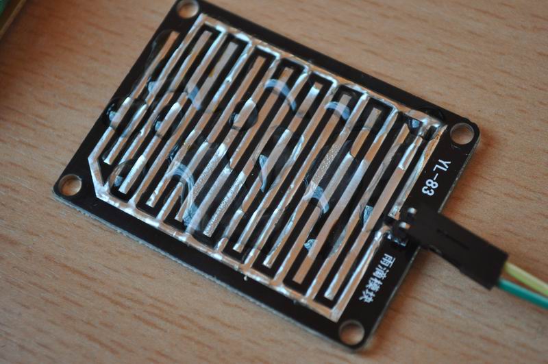
I’ve bought a rain sensor, recently, that should be able to provide a simple piece of information: wheter it is raining or not. The sensor is composed of a metallic grid, to sense the falling rain droplets and an amplifier.
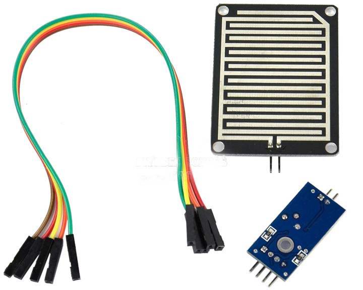
As an output it has a Digital output (high and low states) where the output is adjusted via a pot over the desired threshold, and an analogue output that can be read via an ADC port with a microcontroller. Here is a demo video:
To circuit diagram is simple, so I will not draw that again. Just the Atmega8, a 2×16 LCD and the sensor connected to one of the ADC ports. I used PC0, but feel free to use any other pin.
When there is no water on the grid’s surface, the sensor outputs the max voltage (5V), and this decreases proportional to the quantity of water.
There are similar sensors for sensing soil moisture using the same approach, but with a different grid shape:

As you can see, the amplifier boards are identical.
I am considering mounting the rain sensor either in inclined position and get the output as a function of rain debit, or in horizontal position. For the latter I might also cover the sensitive area with a thin layer of sponge. Not yet sure what the best approach is, so I will adapt the setup according to my findings. The sensor is to be added to the uRADMonitor radiation surveillance station, to correlate humidity and pressure data with the rain events.
One drawback I found so far, is the relatively high current in the sensing electrodes. The current is so high, that I actually get bubbles as a result of water electrolysis! Not a concern for the data readings, but a big concern for the electrodes, that are corroded in this process. I tried covering them with some extra solder, but not sure how much it will hold.
The source code, designed for Atmega8, is available here.
I think it would be better to completely cover the electrodes with something (laquer, tape, resin, etc) and measure the change in capacity.
A denser pattern would help but even this should work.
Of course you can’t just use a DIO pin; you may need some higher frequency circuit.
You might try outputting square signal from a DIO pin on one electrode and rectifying and measuring the other electrode on an ADC pin.
Good luck.
By the way, I’m impressed with all the work you’re doing 🙂
Cata
Cata, this is excellent timing, I was just thinking about a solution the last days. Thank you!