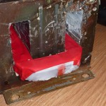
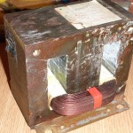
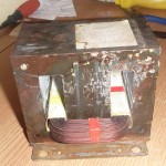
The microwave over transformer can handle 700Watts of power or more. It is therefore a good alternative as a cheap high power transformer, if proper modifications are done:
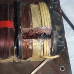
It is possible to remove the high voltage windings and instead add a few turns of thick wire, for a low voltage, high current transformer.
As a simple rule, when winding the new secondary, a copper wire with a section of 1mm^2, can handle a current of 3Amps continuous use, or 5Amps max for short use. 2.5mm^2 section wire, can therefore handle 7.5A for continuous use, or 12.5A for short use.
 |
 |
 |
 |
 |
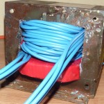 |
Before starting to wind the secondary, we need to know how many turns we need for a given output voltage. In my case I needed 3 separated secondaries, one for 6.3V, one for 12.6V and one for 24.3V. The first two are for powering filaments of high power vacuum tubes . To determine the voltage/turn ratio, wind one turn and measure the voltage using an AC multimeter, or for better precision, wind 5 turns, measure the voltage and divide by 5. Yes, the output voltage is proportional to the number of turns based on the voltage/turn ratio. In my case the ratio was 0.9V/turn.
For 6.3V I needed 7 turns, for 12.6V the double, and for 24.3V 27 turns. Keep in mind that the metal core of the MOT cannot be dismantled, so you’ll need to wind the transformer as it is, using very long pieces of wire, inserted carefully around the core. Not easy, but do-able. I used PVC insulated wire (not the best choice but it was all I got), 1.5mm^2 for 6.3V and 12.6V and 2.5mm^2 for the 24.3V.
So my 3 secondaries can output the following voltages:
6.3V at 4.5A max (7.5A for short term use)
12.6V at 4.5A max (7.5A for short term use)
24.3V at 7.5A max (12.5A for short term use)
So I ended up with a rewound mot, capable of outputting 28.35+56.7+182.25=267.3 Watts. A little downgrade but it’s fine since it suits the purpose.
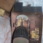
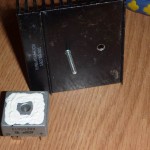
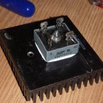
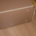
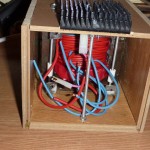
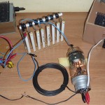
I’ve built a nice wooden case, a rectifier and a tripler, and you can select the AC output to be used for these two:
 |
 |
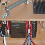 |
 |
 |
 |

I m thinking to build a MOT with enameled copper wire at the secundary,at 13.8 volts high current to power a car amplifier (600w) but the question is if the MOT can handle for continuos work About a couple of hours .I’ve hear that the transformer gets very hot so fan cooler is advise so is enough to keep the MOT cool ?. Thanks
Hi Roger. Yes it gets hot because the iron core gets very close to saturation. A solution might be to rewind the primary for a bigger number of turns, but it doesn’t make much sense.
For minimizing headaches with your amplifier, I suggest you get a proper transformer for this task. With a mot, you’ll need to let it cool after only a few minutes of operation. A fan cooler will not help, as it cannot push air deep inside the primary coil, so the wire would eventually burn with a bang.
hi Radu Motisan. i want to know .how many turn needed for primary side . and which gauge wire , and transformer cross section area .. thank you.
Roger,
Way too later of a reply but I will post it anyway. If you want to power car audio equipment on the cheap look into server power supplies on ebay. Try to get one with a built in fan. They are capable of more than 1500W at 12.5VDC ! If you look around they can be had for $20 and are a great deal for anything that needs 12V DC without a battery. If you do get one look on RC groups website in the batteries and chargers section for the pin-out because you will need to make a jumper to power it on, you may also find out how to raise the output voltage to 13.6V with a resistor jumper while there as well..
Radu, Great website, Somehow Ive stumbled in here and each time Ive found something interesting. I love messing around with MOTS but I always take off the secondary because as you know that secondary will more than likely kill you. Im a electrician with 25yrs experience and work on 3 phase 480V industrial equipment live all of the time, but Im scared of that MOT secondary! When rewound with a few turns of thick wire they are less dangerous and I’ve measured 300A at around 5 volts. Great fun to watch a 3/8″ bolt melt between the secondary in seconds!
Thanks Chris!
Hello Radu. I was looking into AWG tables and realized that if one use several smaller gauge wires to compose a target area section, in order to hold more current, one will note that by the AWG tables, 2 smaller section wires that hold a total sectional area the same as a thicker wire will withstand more current (probably due to surface-current). So if one AWG 3 wire (26,7 mm2) can hold 85 A, 2 x AWG 6 (2 x 13,3) can hold 110 A. If I can take 5 x AWG 10 enameled wires and make “a single one” I could get same area and a current of 150 Ampères of constant load. I don’t know if one should twist the enameled wires or make 5 parallel coils and tie them together in the end. Do you agree?
Best regards
Lissandro
I have seen several comments recently about surface current or skin effect. I looked it up and at 60 hz the depth of the skin effect is around 8 mm. The thickest wire i cold find specs for was # 0000, which is 11mm in diameter. that means the skin effect goes deeper than this wire is thick. In other words, unless you are the power company fugedaboutit. Of course if you are playing with higher frequencies like in a ZVS it is a much diffrent story