Update October 21, 2012: This design is obsolete. It will work, but it contains several mistakes. See the newer design: V3
Because the recent events in Fukushima, Japan, brought a lot of concern on radiation levels, by popular demand, here is a simple Geiger Muller counter using the Russian tube SI-22G and a single transistor regulated inverter that puts out 400V, as required. The complete setup has been assembled in only 5 minutes, so this is a very simple detector, but can prove useful because of the excellent sensitivity:
The radiation is indicated by a led and a small speaker. Each pulse (flashing led and the clicking sound) represents a radiation quantum passing through the tube.
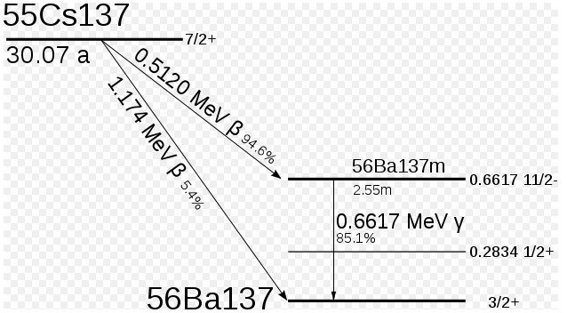
To exemplify I’ve used a small source of radiation, the Eii-43-100 Spark gap radioactive tube, containing less than 0.9uC of Cs137, emitting aprox. 1uSv/h of gamma radiation. The detector reacts promptly to the presence of the Spark Gap tube, the frequency of clicks increases, much over the background level.
Circuit diagram:

This design can be used with a large variety of Geiger tubes, but the output voltage and the limiting resistor might need to be adjusted accordingly. For the SI-22G, the parameters are:
Recommended Operating Voltage (volts) 390
Initial voltage (volts) 285-335
Plateau length (volts) at least 100
Maximum Plateau Slope (%/1 volts) 1.25
Gamma Sensitivity Co60 (cps/mR/hr) 540 (sbm20 has 78)!
Inherent counter background (cps) 1.3
Tube Capacitance (pf) 10
Resistance (meg ohm) 9-13
Maximum Length (mm) 220
Maximum Diameter (mm) 19
To get an idea on a correlation between the clicks and the real radiation dose, I’ve placed the excellent Radex RD1706 dosimeter close to the homemade geiger setup and the radioactive spark gap:
The radiation level detected corresponds to 0.82uSv/h. Here are some pictures:
 |
 |
 |
 |
Can you please provide the circuit schematics, please. What transformer is that and from where you purchased ?
I’ll upload the circuit diagram after I draw it. The transformer is a small ferrite core transformer taken from a PC power supply and rewound for this project: 25turns primary, 10 turns feedback, 120turns secondary. It is not critical, you only need to make sure it puts out close to 400V at very low current.
The German electronics magazine “Elektor” has published 3 old Geiger counter articles for free download (after registration). Two of them contain schematics. Sorry all the articles are written in German …
Oops, I forgot to attach the web link:
http://www.elektor.de/jahrgang/2011/april/online-extra-geigerzahler-im-selbstbau.1747968.lynkx
I liked your video with discharge lamp for test. Thorium?
I test with potassium (KOH or KNO3. KOH is fertiliser. Now start to wonder if it is clever to use it in agriculture. (K has two isotopes and one is radioactive).
I have put togather a Geiger counter recently for experimenting.
My webpage with documentation:
http://barbara320.gotdns.com/
interesting, thanks for sharing!
Nice project! Other similar circuits of interest:
http://www.mare.ee/indrek/geiger/
http://www.techlib.com/science/geiger.html
Could you please upload a scan of the tube specs?
Thanks Janis. The tube was a spark gap containing small amounts of cesium 137.
I just uploaded the schematics for this detector. A low power inverter (with MJE3055) and a small signal amplifier (with 2x2n5551)
I have a question on the transformer, the wire diameter that is needed? Here we speak only of turns
for the primary I’ve used 0.3mm CuEm , for the feedback and secondary 0.14 mm (thin) wire.
I really like the simplicity here, how much current would the circuit draw at say 4v? I plan on running this with one lithium ion cell so thats a Vin range from 4.2 to 3v. Also, what would I have to do to jack the voltage up to around 900v? just add more zeners?
Thanks Gwain , you can go for more zeners in series or use a regulator tube.
You can make it work for 3 V as well, just add a few more turns for the secondary of the ferrite transformer.
The current is low, I don’t remember the value.
Nice, one more thing would it work if I were to attach a small digital frequency meter in parallel with the speaker?
Is this geiger tube ok for this circuit?
http://goo.gl/dGD7c
it depends on the radiation levels you are willing to detect
Can I use this guide for building the transformer?
http://tacashi.tripod.com/elctrncs/inverter/inverter.htm
yes
great,thanks for quick response.I have one more question,what’s the difference between MJE 3055T and MJE 3055 transistors?
I’m a little slow 🙂 how is ac generated in the primary?
thanks
jaymahn, it’s the purpose of that transistor to work as an oscillator and provide AC from the DC supply.
OK, thank you, I thought that. I’m not asking for electronics 101, but how is the oscillation introduced? Is it the result of positive feedback, are the resistors critical? I’m getting more familiar with biasing, impedence, collapsing magnetic fields (with the resulting voltage spike).
No, the resistors are not critical, initially, the transistor is open, so when you connect the battery, the voltage will go through the transistor directly in the primary, producing a magnetic field. This field induces a negative voltage in the feedback, which closes the transistor. This is why the circuit only oscillates if created correctly, sometimes you will need to reverse the feedback connections or even the primary to match the resulting voltages correctly.
When the transistor is closed, the voltage to the primary is suspended, the feedback will produce no voltage, then the transistor will conduct again, and so on, the cycle resumes.
Good explanation, gives me a place to start now 🙂 Thanks again very much.
what type of capacitors did you use, i searched for 2kv 10nf and found none
forgot to ask if a 1kv or even a 630v would work, since my geiger tube is only ~450v
what if i used a toroidal transformer made from an inductor from an old power supply? i tried disassembling those little EI transformers and all 3 of them broke >:(
I had some trouble dismantling those myself, they are all glued together and rarely can one be taken apart safely. If ferrite breaks, you can still glue it back together using cyanoacrylate glue and it will work .
You can try using those toroidal inductors, I see no reasons why they should not perform well and even better. I had this idea myself but didn’t try it yet, so if you build one, let me know how it works.
okay, i only built the oscillator circuit with all the right parts and a toroidal transformer(i used 20T primary, 10T feedback and ~60T secondary because i was out of wire and this was only a test circuit anyways), but i had to lower the resistance from 460ohm to around 180ohm for 6Vac in the secondary(the MJE3055 wasnt open with 460ohm), so wth happened>?!
I have the SI-22G tube, but im having trouble to know which is the anode and the cathode electrodes of this tube. Is the anode the tube its self marked with the symbol + ?? Is this important to know to operate the tube?
Ok, nevermind the questions above. I know how the tube works now.
Good. You need to do a little bit of research, it you want to get any results at all.
is this transformer suitable? http://www.ebay.com/itm/EI-14-Audio-Output-Transformer-1K-8-32-ohm-FS-/160725361500?pt=LH_DefaultDomain_0&hash=item256bfa635c#ht_1205wt_1270
Unfortunately no, you need a ferrite core transformer, and the one on ebay has iron core. Iron can be used, but with circuit modifications.
Are there any ready tranformers at market for this circuit,that i can buy?
Hi,
I build the transformer for this circuit (P=20, F=10, S=150) but my oscilloscope shows only 45 volts peaks 188 Khz when connected to the secondary output of my transformer.
I though i made a mistake when i build the transformer so i build another one (P=25, F=25, S=290) . I still do not have enough voltage = 92 volts peaks 80 Khz
Do i have to make more secondary windings ? Did i made some mistake on the transformer or do you thing it is something else ?
Thanks again for sharing your experience on the web.
Your ferrite core might be of different characteristics. Increase the number of secondary turns as required, until you get 400V.
Please see my geiger counter version 3.2 , instead of this one.
If I look with an oscilloscope then the voltage decreases because of oscilloscope input resistance typically 1 Meg.
Try to measure with some multimeter.
The tube will simply not click if voltage is too low.
Awesome circuit! Im looking to make one from a hacked disposable camera flash unit… however not quite sure how to make the audio circuit for it. Would this schematic work with the HV components taken out, to simply act as the audio circuit?
Thank you,
Bob
Hi Bob,
I’m glad you like it, however this is an obsolete implementation and my advise is you look at the more recent Geiger counters I’ve built. Here is a good start:
http://www.pocketmagic.net/2012/10/diyhomemade-geiger-counter-2/ with the circuit diagram available at: http://www.pocketmagic.net/wp-content/uploads/2012/01/geiger_counter_32.png
Now, to answer your question, yes you can use the “audio circuit” directly to your setup. Add the R2 resistor at the HV output, and continue with the right part of the circuit. Let me know if you have any other questions.