If you’ve used Leptonica, you probably know it’s a great library, but when you want to use it to replicate Photoshop like effects, you will quickly get to want more than what the library provides by default.
Take the pixGammaTRC primitive as an example: If you want to modify the lightness of your image, (making it brighter or darken it), or even a simple contrast this might work good enough. But what if you’d like to make more sophisticated image transformations like enhancing only the shadows of the blue light color component of RGB? Long sentence, I know 🙂 but I had to solve this question today! And while searching and hoping to find something working out of the box, I came to the conclusion that this is a job I should be implementing from scratch!
But you might ask yourself, for what in the world would I use it for, considering all the complexity and time involved in making it? Actually there are so many image effects that use curves, I cannot even think of one I’ve made without them. So take that as a motivation 🙂
Recently I added a new image processing technique, to my image processing software. It’s called Lomo. You must have heard about it, or if not, you’ve probably seen it in so many pictures nowadays, you know its vintage look – so popular now and the one that Instagram is mostly using to create the old image look. Well not exactly..Instagram is somehow tweaking it with simply applying some overlay filters, but this is not the purpose of this post, so let me tell you more on how you can really achieve it programatically.
What are the Curves?
First you should understand how curves work. If you’ve use Photoshop, you probably already know this. Basically it gives you the possibility of enhancing or reducing the lightening of an image for shadows, midtones and highlights, separately on each color light components or for all together.
My Lomo effect, besides other image processing effects, like noise, blur on the margins, vignetting, etc, requires using a more complex Curves transformation: More precisely, enhancing the highlights of the red and green components, while reducing their shadows, all this to create the S shape curve, while giving an opposite effect of an inverted S shape to the blue light: what this does is enhancing the shadows and reducing the highlights. You can see this better in the right side thumbnail from the image below, taken from Photoshop:
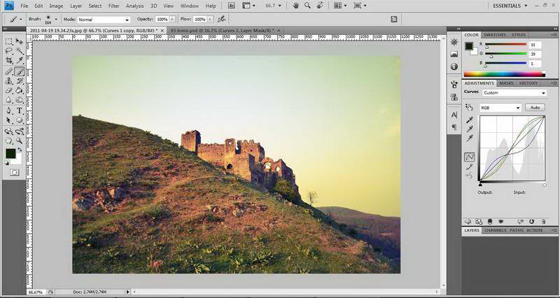
You can see this effect alone, has given enough vintage look to my image. Now this is how I’ve made it programatically:
Note: You can use as many MAX_CURVES_POINTS as you prefer..
float LineFunction(float px, float p1, float p2, float v1, float v2) {
	//f(x) = ax+b
	float a = (v2-v1)/(p2-p1);
	float b = (v1*p2-p1*v2)/(p2-p1);
	return (a*px + b);
 }
 int GreedyFindInterval(float px, float p[MAX_CURVES_POINTS], int left_index, int right_index) {
	int  middle_index =  left_index + (right_index - left_index)/ 2;
	if(right_index == left_index+1)
		return left_index;
	else if(px < p[middle_index])
		GreedyFindInterval(px,p,left_index,middle_index);
	else if(px > p[middle_index])
		GreedyFindInterval(px,p,middle_index,right_index);
	else return left_index;
 }
//pixSrc - pixel source, pt_val - value for points on curves, res_pt_val - the desired value for the points on curves, np - number of points on curves
PIX * CurvesWithPoints(PIX *pix8, float pt_val[MAX_CURVES_POINTS], float res_pt_val[MAX_CURVES_POINTS], int np) {
	PIX *pixCurves = pixCopy(NULL, pix8);

	//left and right interval to begin with for the greedy interval search function
	int li = 0, ri = np-1;

	l_int32  w,h,wpl,d;

	pixGetDimensions(pixCurves, &w, &h, &d);

	wpl = pixGetWpl(pixCurves);

	//get the data for the pix
	l_uint32 *data = pixGetData(pixCurves);
	l_uint32 *line;
	l_int32 val;

    for (int i = 0; i < h; i++)//line index
	{
		//jump to the line for each data string
		line = data + i * wpl;
        for (int j = 0; j < w; j++)// columns index
		{
			//get the byte for the pix, that is max 255
			l_int32 val = GET_DATA_BYTE(line, j );
			//find the left bound curves interval index that the pixel fits in, the right bound will be left+1
			int left_int_index = GreedyFindInterval((float)val,pt_val,li,ri);
			int right_int_index = left_int_index + 1;
			//find the resulting color value factor, based on line function. fc is in [-1..1] interval
			float fc = LineFunction(val,pt_val[left_int_index],pt_val[right_int_index],res_pt_val[left_int_index],res_pt_val[right_int_index]);
			//negative values decreases the color light, positive increases them, 0 remains the same
			if(fc >= 0) val += fc*(255-val);
			else val += fc*val;
			//put the modified data byte, back in
			SET_DATA_BYTE(line, j, val);
		}
	}

	return pixCurves;
 }
A few details
For the input image we extract the three color channels, R,G,B . These are actually 8bpp images, equivalent to grayscale. Combined they form the normal RGB colored image.
For each of the three channels, we define a set of points that form the transformation function, a math graph represented by the curvy line in the photoshop screenshot. For simplicity , I opted for linear equations, instead of the round, square functions illustrated by the Photoshop thumbnail. The performance is better and the result the same.
The transformation functions applies to all grayscale values, from 0 to 255. Here those closer to 0 are the darker colors, going to the lighter ones at 255 end of the interval. Our function takes these values, from 0 to 255, and for each returns a number in the [-1,1] interval, according to the way we defined the function with the initial set of points. If the function result is positive, we will get an increase of the current grayscale value. For 1, this is the maximum of 255-Current_Grayscale_value. For negative values, we decrease the current grayscale value.

The continuity of our function guarantees the smooth looks of the image – if this aspect is omitted we would get ugly artifacts. I know it’s a lot to digest, but the code does even more, when building the transformation function (the “curve”) out of the initial set of points.
Calling the function from main loop:
int main(int argc, char **argv) {
	//read the pixels of the image
	PIX *pixSource= pixRead("tmp/01_orig.jpg");
	//get the R, G, B components from the image pixels
	PIX *pixRGB[3] = {pixGetRGBComponent(pixSource, COLOR_RED), pixGetRGBComponent(pixSource, COLOR_GREEN), pixGetRGBComponent(pixSource, COLOR_BLUE)};
	//set the information for the Lomo look, this is made empirically by me
	float p[3][MAX_CURVES_POINTS] = {{0,60,180,255},{0,60,180,255},{0,60,180,255}};//the left 0-black and right 255-white bounds are always required, so you only add what's in between, in this case we add 2 points
	float v[3][MAX_CURVES_POINTS] = {{0,-0.15,0.30,0},{0,-0.2,0.29,0},{0,0.15,-0.35,0}};//{0.0,-0.3,0.3,0.0} is an S shape curves while {0.0,0.3,-0.3,0.0} is an inverted S shape
	int np[3] = {4,4,4};//min is 3
	//apply curves for each color light component according to the settings given above
	for(int i=0;i<3;i++)
		pixRGB[i] = CurvesWithPoints(pixRGB[i], p[i], v[i], np[i]);
	//recreate the pixel
	pixCurves = pixCreateRGBImage(pixRGB[0], pixRGB[1], pixRGB[2]);

	//free memory
	for(int i=0;i<3;i++)
		pixDestroy(&pixRGB[i]);

	//create the image on the computer
	pixWrite("tmp/04 Lomo curves.tif", pixCurves, IFF_TIFF_G4);
}
And the result
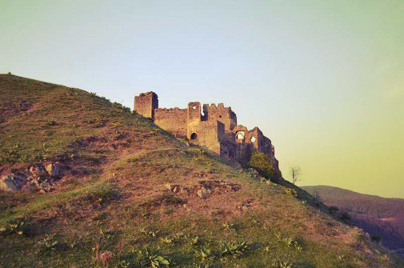
Here you can see my result, the output image of this code, is visually identical to the Photoshop effect. Success!